March / April
Ir-;)
o
~
.
.-..
.
. BENDIX G·20-PAGE 14
I I
I I RPC 9000-PAGE 23
PB 250-PAGE 52
Now ... one microsecond
, TM I
pioneers again to make commercially available a newly devel-oped advanced core memory product. Type LQ memory products provide a complete clear/write and read/restore memory cycle at rates to one megacycle, utilizing a new word-select design tech-nique. These products are offered by Telemeter Magnetics in any form desired - from cores to complete memory systems.Cores
For those memory manufacturers who prefer to wire their own arrays, TMI word-select ferrite cores may be ordered now. These high speed cores provide extremely fast switching with low drive current.Arrays and Stacks
You may take advantage of the skill and production efficiency developed at TMI in manufacturing millions of cores, most of which have been assembled into arrays and memory stacks. This know-how is being applied to assembly of the new word-select cores into configurations to meet virtually any high speed computer design need.Memories
A new ultra-speed memory-the Type LQ-is available for commercial delivery in late ,1960. Operating speeds up to 1.0 microsecond random access cycle time are now economical and ·result from the development of special ferrite cores and advanced driving and sensing circuits. The LQ word-select memory permits application to a wide variety of speed and capacity requirements.TELEMETER-MAGNETICS I n c
P. O. Box 329, Culver City, CaliforniaData Equipment Division, 9937 Jefferson Blvd., Culver City, Calif. Components Division, 2245 Pontiu,s Ave., Los Angeles, Calif.
6$Cil'Ogra~""'ShOWing':~ti~e"""~I~","·and
switching time, for, TM ,,301~02 core.
Time
scaleO~2/.t$/divi'$ion.' ", ' ' ,,' 'VISIT US
AT THE
IRE SHOW
BOOTH 1900
For complete specifications or to dis-cuss your problem with a TMI applica-tions engineer write or call
PIONEERS IN DEVELOPMENT AND MANUFACTURE OF CORE MEMORY PRODUCTS
Circle 1 on Reader Service Card.
Marchi April 1960
SPACE
TECHNOLOGY
OFFERS WORK OF THE FUTURE ... TODAY
Computer Programmers
and Applied Mathematicians!
High speed digital computers and expanding computing and data
handling systems require individuals with more than the usual
amount of interest and ability in the fields of Applied Mathematics
and Scientific Programming.
Our Computation and Data Reduction Center in Southern
California is one of the largest and most advanced facilities in the
nation. Outstariding R&D facilities, a creative atmosphere, and
participation in some of the most challenging computation and
data reduction problems offer optimum individual satisfaction at
ST1. The individual members of our Technical Staff are extended
opportunities for project responsibility and personal advancement.
Resumes are invited.
•
SPACE TECHNOLOGY LABORATORIES, INC.
P. O. BOX
95004,
LOS ANGELES45,
CALIFORNIA2
A new word, which means mor'e than automation,
for it is the custom-fitted application of today's finest
··automation equipment to your particular needs .•.
This announcement is a culmination of Friden's years in integrated data processing. Friden's assumption of responsibility for the most important phase of automation-its practical application.
The first step to PractiMation is a critical analysis of your office. Second, an outline of objectives for increasing its efficiency (without personnel changes). Then, consult your Friden man. He is an expert, and has solved a good many problems like yours. His help can be invaluable.
Next, you need equipment that can be used by your present employees without special training; equipment which is sanely priced, easy to install. And, above all, equipment which is expansible with your business.
Here are some good examples:
A. Friden SBT Calculator- the famous "Thinking Machine of American Business." Touch.one-key simplicity. Performs more steps in figure. work without operator deci-sions than any other calculating machine ever developed.
B. Friden COMPUTYPER® (Model CTS)-produces a complete invoice in one operation with virtually no operator intervention. Reads alpha-numeric data from tape, edge-punched cards, or tab cards; accepts variable data through typewriter keyboard. Machine also punches selected data in tape or cards
for statistical reports. The Computyper and any good typist make up an entire billing department.
C. Friden ADD-PUNCH® (Model APT)--':'A Data Processing machine, the APT produces a printed tape, and a punched tape for sub-sequen t processing.
These are just three. Friden'sfuilline of adding machines, calculators, accounting machines, mail room equipment, and "Tape Talk" IDP equipment can fully automate your office. Call your Friden man today, or write directly to Friden, Inc. © 1960 FRIDEN, INC.
F
Ii
de n
has the sYS,temFRIDEN, INC., SAN LEANDRO, CALII'ORNIAe SALES, INSTRUCTION AND SERVICE THROUGHOUT U.S. AND WORLD.
Circle 2 on Reader Service Card.
a commentary
QUO ANIMO?
by JACKSON W. GRANHOLM
The year 1959 was memo~able for a number of things. Not the very least of these was the publication in DA-TAMATION of expurgated, quasi-verbatim accounts of parts of a ses-sion held March second at the RAND Corporation in Santa Monica. Various greater or lesser lights (yr.obt. author included) were invited to this meet-ing. It was a no-holds-barred, let-your-hair-down (where possible) kind of thing.
Reaction to this session (and parti-cularly to its publication) was re-markable for two reasons. The first was that this reaction was rather vio-lent. A massive and untoward amount of wailing, teeth gnashing, garment rending, and crying-towelmanship came to pass. The second reason, de-pendent upon and stemming from the first, is that the session can hardly have been that important.
This latter viewpoint is expressed quite succinctly, if brutally and truc-' ulently, by the Honorable Wolf J. Flywheel (possibly a pseudonym?) of Camden, New Jersey, in his letter to the Editor of DATAMATION (Vol-ume 5, Number 5, Page 2). Flywheel indicates that, in his opinion, the whole matter is ridiculous.
Certain noted past presidents of ACM were reported by competent ob-servers at the fall, 1959, ACM session in Boston to have become positively livid over the RAND session, illus-trating the first point above.
Now all this is hardly without his-torical precedent. The independent or-ganization, founded on . common terest, and organized around such in-terest, is one of the most time-hon-ored institutions in our nation. The Revolutionary War was won by what was, essentially, a loose amalgama-tion of independent organizaamalgama-tions.
Today there exist many such or-ganizations, some of which do work
(Continued on page 50)
DATAMATION is published bi-monthly on or about the first day of every even-numbered month by F. D. Thompson Publications, Inc., Frank D. Thompson, president. Executive, Circulation and Advertising offices, 141 East 44th St., New York 17, N. Y. (MUrray Hill 7-5180). Editorial offices, 10373 West Pico Blvd., Los Angeles 64, Calif. (BRadshaw 2-0817). Published at Chi-cago Illinois, accepted as controlled circula-tion publicacircula-tion at Waseca, Minn. Copyright 1960, F. D. Thompson Publications, Inc.
The Data-Stor Model 59 Digital Tape Transport is
ideally suited for use in computer, instrumentation
and control applications.
It
incorporates the highly
reliable features of military tape transports developed
by Cook Electric Company during the past 12 years,
and has been proveIiiin the Atlas, Titan, Polaris and
other missile programs.
These features include exclusive use of modern ultra
reliable solid state circuitry, eliminating gas or
vac-ONE OF MANY E}(AMPLES
OF EXCELLENCE IN THE DATA
HANDLING FIELD
~
Cook Electric Company's
1fIII#
DIGITAL TAPE
TRANSPO.RT
uum tubes. Precise tape handling is insured by
-proportional reel drive servo systems that have no
jerky step servos. Tension error sensing is
accom-plished by synchro transmitters with no unreliable
potentiometers or contact pile-ups. Field adjustments
are eliminated by building tolerances into a single
rugged tape deck casting. Endurance and quality are
assured by strict adherence to the exacting design
and workmanship requirements of MIL-E-4158.
TAPE SPEEDS TO 150 IPS
0LESS THAN 3 MS STOP/START
0REWIND SPEEDS TO 400 IPS. NO PROGRAMMING
RESTRIC-TIONS
0PACKING DENSITIES TO 600 NRZ BPI. OPERATES FROM 5 VOLT CONTROL PULSES OR LEVELS OF EITHER
POLARITY
0FRONT PANEL ACCESS
0CHOICE OF NARTB, IBM, OR SPECIAL REELS. ANY TAPE TO 1"
ItCONDUCTIVE
LEADER, LIGHT TRANSMISSIVE, OR LIGHT REFLECTIVE END OF TAPE·SENSORS
0SOLID STATE READ/WRITE AMPLIFIERS
o
METAL FACED READ/WRITE MAGNETIC HEADS
•
AVAILABLE AS HIGH SPEED PHOTOELECTRIC READER.
Marchi April 1960
Experienced recording systems engineers ·are invited
to apply for existing employment opportunities.
ADDRESS YOUR INQUIRIES TO
8100 MONTICELLO AVENUE SKOKIE, ILLINOIS
Circle 3 on Reader Service Card.
I
A Statement from Allstate Insurance Company: ,
-
~-4
"JIVe
bought our
first Burrouglts
cOlmpute1~
in
1954,
no~v
own seve'n, and have more on order ...
these are big reasons why Allstate will continue to
offer speedier customer service at low cost."
JUDSON B. BRANCH, President of Allstate Insurance Companies
James A. Reynolds, Vice-President of Allstate's Services Department (left) confers with Allstate's President, Judson B. Branch.
Back in 1930, the Sears Board of Directors considered the idea of apply-ing Sears business methods to the sale of automobile insurance. They felt that by selling direct to the public, and keeping operating costs .low, quality insurance protection could be, sold at low rates. And by keeping custorpers satisfied through fast, fair service, they hoped to build and maintain a volume of insurance business that would make the low-overhead methods payoff. They settled on the name "Allstate" for
the new company, and opened the first office in a Sears store in Chicago in 1931.
Since that time Allstate has had a dramatic rise in the insurance industry and has pioneered many new and more efficient ways of doing business.
In its first year, Allstate took in $118,000 in premiums through adver-tising in the Sears Mail-Order Catalog. In 1958, Allstate's volume had sky-rocketed to a whopping $376,000,000. Today, Allstate is one of the world's largest stock companies offering insur-ance of almost every major kind. The company recently added accident and sickness insurance, and boat-owners insurance. Its comparatively new com-mercial insurance lines are booming. Allstate Life Insurance Company, a recently'-formed subsidiary, already has over a billion dollars of insurance in force.
Allstate operates a vast network of zone, regional and district service offices in the United States and' Canada, with foreign expansion now under way in Switzerland. At the pres-ent time there are more than 1,300
sales and' service locations with more than 5,000,000 policies in force. One of the big reasons behind Allstate's growth is its dedication to customer service through fast, fair claim settle-ment, prompt response to inquiries, and lower premium costs. A powerful tool in aiding the company to provide .swifter and 'better service is its use of Burroughs electronic data process-ing systems.
After a careful analysis of their needs, Allstate purchased a BUl:roughs
Allstate's Assistant V ice-President and Head C?f Research, L. L. van Oosten.
205 Computer, with magnetic tape equipment, in 1954. With the many complexities of insurance rating, endorsements, billing and coding, All-state found the computer extremely useful in "cutting red tape" and speed-ing up policyholder service. More and more policyholders discovered that the protection they purchased through their Allstate policy was delivered promptly because the time consuming annoyance of manual handling was now replaced with electronic methods. Allstate also used the computer for statistical and management reports assembled in a fraction of the time for-merly required. ,
In 1957 and 1958 Allstate purchased three more Burroughs 295's and used
,cthem for billing; accounts receivable, rating policy issuances, and endorse-ments. When Burroughs announced its large 220 System, with 'expandable core memory, Allstate purchased three of these and had them installed in 1959. More 220's are scheduled for installation this year.
In speaking of the over-all benefits to Allstate from its use of Burroughs Computers, Mr. Judson B. Branch, Allstate's President, said, "Pri.marily, we've been able to give our customers faster, more efficient service at much lower costs. The computers help us to 'cut red tape' and thereby speed our service and help us provide insurance at lower rates. They a~so provide us
with a means of absorbing our substan-tial growth without a corresponding increase in our operating expenses. We've had other benefits, too. By developing vitally needed statistics, our compu.ters have made available, on a regular reports basis, valuable up-to-date information for our management. In addition, they enable us to promote many of our present employes to posi-tions of greater importance, produc-tivity and interest:'
In a company where efficient busi-ness methods have been a key factor in providing better service at lower rates, the cold eye of economic justification is constantly focused on its Burroughs equipment. A continual assessment and appraisal of its electronic data process-ing program has been made over the last five years.
As a result of its analysis, Allstate is not turning back, but relying on Burroughs for a continuation and expansion of its electronic data process-ing program.
There are hundreds of. other com-mercial and industrial users doing the same. Burroughs' complete line of elec-tronic computers is backed by a coast-to-coast team of computer specialists, all prepared to tell you how Burroughs can help you in your business. For additional information, write Electro-Data Division, Pas~dena, California.
Corporation
"NEW DIMENSIONS/in electronics and data processing systems"Circle 4 on Reader Service Card.
6
Commercial expansion at National creates
IMPORTANT
DIGITAL COMPUTER R&D POSITIONS IN LOS ANGELES
TRANSISTOR CIRCUITS .ENGINEERS-Senior and Intermediate
Highly creative positions are available in circuit analysis and design. Duties include advanced mathematical studies in transistor circuitry, evaluation of transistor circuitry, component studies and keeping abrea·st of computer circuit advances. Circuit analysis ability.and solid under-standing of transistor theory essential. E. E. degree required.
DESIGN ENGINEERS-Senior and Intermediate
Opportunities available for graduate E. E.'s with 2 years of ferrite magnetic core design experience. Transistor design experience helpful. Work will entail ferrite core design on general-purp·ose digital buffers. .
ELECTRONIC PRODUCT DESIGN ENGINEERS
To form nucleus of a new product engineering and manu-facturing liaison group. Positions require 2-3 years of elec-tronic design experience, preferably in digital computing
equipm~nt or transistor circuits.
SENIOR PROGRAMMERS
For development of advanced automatic programming techniques for a general-purpose data processor, accep-tance testing, etc. Experience should include construction of auto codes, service-type routines, simulators or diag-nostic routines.
RECENT GRADUATES
Excellent opportunities for recent graduate engineers with 6-18 months' experience. Positions are in the areas of transistor circuit and magnetic circuit techniques, logical
design. . .
Please send resume to D. P. Gillespie, Director of Indus· trial Relations
~~*
The National Cash Register CompanyELECTRONICS DIVISION 1401 E. EI Segundo Blvd., Hawthorne, Calif.
*Trade mark reg. U. S. pat. off.
Circle 70 on Reader Service Card.
Radar Tracking Computers
High Speed Repetitive
Display
MC-5900 Process Master Analog Computer
MC-3302 Transistorized
Data Plotting Board
MC-5800 Precision Master Analog Computer
MC-70l Electronic
Multiplier Linear Programming Computer
DYSTAC
A NEW COMPUTER TECHNOLOGY
solving problems hitherto unsolvable
DYSTAC (Dynamic Storage Analog Computer) sy~thesizes theadvantages of both analog and digital computers. DYSTAC com-bines the analog's speed, lower cost, ease of programming, and improved output data presentation with the digital computer's unique capacity for data storage and time sharing of computer elements. With DYSTAC you can now solve the most complex problems, ranging from distillation column design to multi-dimensional heat transfer ... from boundary value problems to transport lags.
In distillation column design, for example, DYSTAC employs only 44 amplifiers on a four-component problem; the number of amplifiers required is independent of the number of plates. With any other analog computer each plate must be reproduced in the circuitry-for a 3D-plate column, over 1200 amplifiers are needed unless manual reprogramming is employed. What's more, only
DYSTAC yields a plate-by-plate display of all column conditions. In heat transfer studies, DYSTAC will speedily and accurately solve hitherto unsolvable partial differential equations. It also makes practical for the first time instantaneous solutions to such trial-and-error problems as automatic optimization, automatic correlations, data fitting, probability 'distribution, Fourier analy-sis, convolution and superposition integrals and eigenvalue.
When you 'buy a CSI computer with DYSTAC you are buying more than the finest general purpose analog computer. You buy additional capacity as well as capability. For when DYSTAC ele-ments are not in use as memory devices they are available to the computer as operational amplifiers. Planning to interconnect
digital and analog computers? DYSTAC is the answer.
See DYSTAC in operation at our plant. If you can't attend a demonstration write, phone or wire for full information.
COMPUTER SYSTEMS, INC.,
611 Broadway, Ne~ York 12, New York, SPring 7-4016A Schlumberger Subsidiary formerly Mid-Century Instrumatic Corp.
8
NOW I A NEW CONCEPT
IN COMPUTER DESIGN
SETS A NEW STANDARD
OF VERSATILITY AND VALUEI
THE FULLY-TRANSISTORIZED
R'PC-4000
, I
COMPUTING
Marchi April 1960
The RPC-4000 is a new, fullv-transistorized electronic computing system with th~ iargest memory, greatest problem-solving capacity and flexibility in the low- or medium-priced field. It is the latest member of a grow-ing family from the people whose LGP-30 has become the world's leading small-scale computer.
Wide range of applications: the RPC-4000 has been de-Signed for engineering, scientific, business data process-ing and management control functions. Such jobs as product and process design, statistical analysis, research, inventory control, payroll and sales analysiS are all well within its capabilities.
Easy to use: the RPC-4000 is simple to program and operate. Royal McBee compiling and translating routines allow even non-technical personnel to obtain maximum results. Versatile command structure gives programming speed and flexibility.
Available at low cost: high capacity, flexibility and ease of operation make the RPC-4000 the outstanding com-puter value on the market today.
Minimum operating costs: the RPC-4000 requires no site preparation or special maintenance. It is powered from
any ordinary wall outlet. .
Continuing assistance: users benefit from free training, an information exchange service, and library of programs.
Heart of the RPC-4000 system is a new transistorized computer with advanced design concepts that pro-vide substantial computing speed and capacity in a low-cost unit. Magnetic memory drum stores 8008 words. Operating speeds are as
high as 230,OOOjminute.
Standard input-output is a tape typewriter system which includes a Royal electric encoding - decoding typewriter complete with desk and chair, plus a tape punch-read con-sole. Read speed is 60 characters/ sec., punch speed 30 characters/ sec. Typewriter, punch and reader may be interconnected in any com-bination for both on-line and off-line operations.
A new 500 character/sec. photo-electric tape reader and a 300 character/sec. punch are available as optional input-output equip-ment. A magnetic tape unit and a line printer will be available soon. As many as 17 input-output devices ( 60 with minor modification) may be connected on-line to the basic system. All peripheral equipment is under automatic program con-trol of the computer .
• -e
~rj Royal Precision CorporationRoyal Precision is jOintly owned by the Royal McBee and General Precision Equipment Corporations. RPC-4000 sales and service are available coast-to-coast, in Canada and abroad through Royal McBee Data Processing Offices. For full, de-tailed specifications on the new, transistorized RPC~4000, write ROY A L M C BEE data processing division, Port Chester. N: Y
Circle 6 on Reader Service Card.
FREE BOOKLET
FROM DUPONT
• Free, 12-page booklet of charts and test data compares performance of "Mylar"* polyester film with cellulose-acetate tape base. Booklet includes sample strips for you to make a simple comparison of the greater toughness of "Mylar". It's free ... no obligation ... mail coupon or write for your copy. E. 1. du Pont de Nemours & Co.
(Inc.), Film Department D-3, Wilmington 98, Delaware. *"Mylar" is Du Pont's trademark for its brand of polyester film.
C[()POtiP
REG. U.s. PAT. OffBETTER THINGS FOR BETTER LIVING . . . THROUGH CHEMISTRY
DU PONT
MYLAR®
POLYESTER FILM
MAIL COUPON FOR FREE BOOKLET ...
r---~
I
E. 1. du Pont de Nemours & Co. (Inc.)I Film Department D-3, Wilmington 98, Delaware
I
I
IPlease send me new booklet giving data on Magnetic Instru-mentation Tapes of "Mylar".
I Name _ _ _ _ _ _ _ _ _ _ _ _ T i t l e
-I
I Company _____________________________________ _
I
Street __________________________________ _l
City Zone State _ _ _ _~---~
PRINTED IN U.S.A. Circle 7 on Reader Service Card.From the computer industry's most experienced engineers
comes a concept which can save your company
millions of dollars in computer cost and manpower
The New Satellite Computer System
The Satellite Computer System is a new and ,ultra-powerful computing concept which permits you to operate data processing centers with maximum
efficiency and economy. The system
employs the two most versatile all-transistorized computers in use today: Control Data's large-scale 1604 Com-puter and the desk size 160 ComCom-puter. In the Satellite Computer System, the desk size 160's are used in small, independently operated data process-ing centers that have direct access to the large-scale 1604 Computer. For example, your company's account-ing department,. engineeraccount-ing depart-ments, and statistical departments can
Marchi April 1960
each operate a 160 in its own center and direct its own data processillg activities. In addition, each center has
direct access at any time to the
tre-mendous speeds and computing capacity of the large-scale 1604. The 1604 has such large capabilities· and great speeds that it can accept data from several such centers while simultaneously processing vast amounts of other data.
Thus, the small data processing center, operating within the framework of the larger center by utilizing the 1604 Computer, can realize a new magnitude of data processing and computing power.
One to six Control Data 160 Computers act as independent "satellite" data processing centers, or work in conjunction with the Control Data 1604 Computer.
• provides flexibility for processing every type of problem-from the largest scientif-ic and business data processing problems to small calculations and routine data processing activities.
• provides for direct transfer of data be-tween 1604 and 160 (or vice versa) without hooking up "black boxes."
• data transferred from 1604 to 160 at rate of 160,000 characters per second; 160 can interrupt 1604 and transmit data at same rate.
• data is also transferred from 1604 to mag-netic tape unit that is directly available to 160 (or vice versa) - 160 accepts th is data from same tape reel on same tape drive used to transmit data to and from 1604, thus eliminating the necessity of changing tape reels between computers.
• large-scale 1604 holds up to 65,000 in-structions in magnetic core memory of 32,768 words-has 48·bit word length, and performs additions in 1.2 millionths of a second.
• 160'sare fast and versatile desk size com-puters - all transistorized with magnetic core memories - execute 60,000 instruc-tions in one second, perform addiinstruc-tions in 12.8 millionths of a second.
~
CONTROL DATA
°ODCO
RPO RAT ION
Circle 8 on Reader Service Card.
501 PARK AVENUE
MINNEAPOLIS 15, MINN.
FEderal 9-0411
One sound solution
to the problem of quickly providing error free
paper tapes to program equipment ranging from
machine tools to satellite communications gear
is Tally/Seattle's Model 150 Tape Console.
Here is a device which fully automates
tape production.
Itis the only unit available
specifically intended for the high speed
preparation, verification, and duplication of
error free perforated tape.
SIMPLIFY
AND
Tally tape consoles are available in ,either vertical or
horizontal cabinets.
AUTOMATE
PUNCHED PAPER TAPE PRODUCTION
WITH THENEW TALLY TAPE CONSOLE
Schematic Arrangement of Components in Tally Tape Console
Basically, the uni consists of an alpha
numeric keyboard, control and comparison section with six-digit decimal display, two tape readers and one tape perforator.
ADVANTAGES,; ..
PUNCH
READER #2
1. Overall system
flexil~ilityand versatility with
full operator control.
3. Produces accurate and complete copy
with-out overpunching, cutting, or splicing of tapes.
2. Keyboard entry to shift register and visual
display which lets the operator edit keyed
in-formation prior to actual tape punching.
4. Tape to tape duplication and/or verification
at up to sixty characters per second.
Want more information? Your nearby Tally engineering representative will be glad to provide you with complete technical information or you may write directly to Department 23
SPECIFICATIONS-OPERATING SPEED: Variable from 0-60 characters per second. STANDARD CODE CHANNELS: 5, 6, 7, or 8. STANDARD TAPE WIDTHS: 0.68.7, 0.875 and 1.000 inch (interchangeable). SUPPLY AND TAKE-UP: 6" reel for 400' maximum; 10" reel for 1000' maximum; Fan Fold for 400' maximum. CODE HOLE SIZE: 0.072" ±0.002 diameter on standard 0.1" centers. FEED HOLE SIZE: 0.047" ±0.002 diameter. ALIGNMENT: Code holes and feed holes have a common center line. POWER REQUIREMENTS: 117 vac ±10%, 60 cps, 500 watts. DIMENSIONS: 511,4" H x 20%" W x 23%". PRICE, f.o.b. Seattle: $8,000.
Prepared by BONFIELD ASSOCIATES, INC.
TALLY
REGISTER CORPORATION
1310 Mercer Street
Seattle, Washington
Phone: MAin 4-0760
12 for Spring issues of Automation, Automatic Control, Control Engineering and Datamation.
the automatic handling of
in formation
volume
6,
number2
FRANK D. THOMPSON Publisher
GARDNER F. LANDON Vice President
SANTO A. LANZAROn A Editor
ETIENNE J. GUERIN European Editor
DR. HERB GROSCH Contributing Ed.
DON B. PRELL Technical Consultant
BEnE L. HOWE Production Manager
MARTHA KNOWLES Circulation Mgr.
LEO MONAHAN Art Director
DANIEL D. McCRACKEN C. L. W ANLASS
Editorial Advisers
RICHARD W. NIELSON Sales Mgr.
WARREN A. TIBBETTS
New England District Manager
434 Webster St., Manchester 4, N. H. NAtional 5-9498
RICHARD W. NIELSON
Eastern District Manager
141 E. 44th St., New York 17, N. Y. MUrray Hill 7-5180
ALBERT PUDV AN
Cleveland District Manager
3537 Le.e Road, Shaker Heights 20, OhIo WAshington 1-9370
GILBERT THAYER
Midwest District Manager
ROBERT W. HEATH
Midwest Representative
201 N. Wells St., Chicago 6, 111. FInancial 6-1026
HAMILTON S. STYRON
Western District Manager
10373 W. Pico Blvd., Los Angeles 64, Cal. BRadshaw 2-2643
E. J. GUERIN
European Manager
Box 824
Stockholm 1, Sweden
Circulation audited by
I ••
~ "_~_Business Publications Audit _ l! !!!.i-,~
Member, Notional
~
Business Publications ~
Marchi April 1960
IN THIS
ISSUE-FOUR NEW COMPUTERS
ARTICLES
2 Quo Animo?-A Commentary
14 The Bendix G-20 System
19 Digital Magnetic Tape Recorders-:-A Survey
23 RPC Quickens Pace-9000 Announced
29 Some More Facts About COBOL
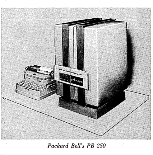
52 Packard Bell Announces P B-250
58 Monroe Enters Small Machine Arena
58 New PACE Feature Announcedby EAI
72 International Standards for Computers
WESTERN JOINT COMPUTER CONFERENCE
33 The Conference, May 3,.4 and 5,196035 A Welcome from the Chairman
37 Technical Program Preface, The Program
46 W ICC Exhibitors
48 Banquet Speaker, Ladies' Activities
DEPARTMENTS
24 Plus and Minus, by Herb Grosch
55 Datamation in Business and Science
60 Datamation News Briefs
63 New Products in Datamation.
73 New Datamation Literature
80 Advertisers' Index
EDITORIAL OFFICES - 10373 W. PICO BLVD., LOS ANGELES 64, CALIF.
THIS ISSUE-29,500 COPIES
DATAMATION Is circulated without charge by name and title to the manufacturers and users of automatic, information-handling 'equipment in all branches of business, Industry, government and military installations. Qualified individuals in the United States and Canada are Invited to request this publication on their company letter-head, stating position and firm's business. Available to others by subscription at the rate of $5.00 annually; single issue, $1.00 when available. No SUbscription agency Is authorized
by us to solicit or take orders for subscriptions In the United States, Canada or overseas. DATAMATION will accept and consider articles dealing with small, medium and large electronic data processing systems; articles covering de-velopment and oppllcatlon of components, sub-systems and sub-systems; and other general arti-cles of Interest to those In the data processing industry. Material submitted should be accom-panied by pictures and illustrations when pos-sible. Unsolicited manuscripts to be returned to writer should Include return postage but editor assumes no responsibility for their safety (al-though all reasonable care will be taken).
THE
BENnIXG~20
DATA,PROCESStN
G:::SYSTEM:
by DAVID C. EVANS, Chief Engineer and CHARLES A. PIPER, Mgr.,Applied Mathematics
Bendix Computer Division
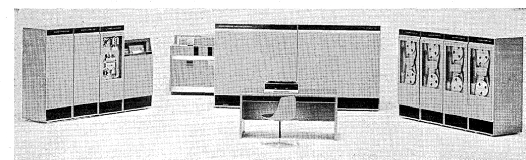
Bendix's new G-20 system is composed of a high-speed
central processor, a control buffer and matched input-out-put units including magnetic tap~, high-speed printer, and' punched card and punched tape equipment as pic-tured in Figure 1. These elements operate in a common language and are interconnected by a communication sys-tem which permits their operation in a wide variety of on-line and off-on-line systems. ,
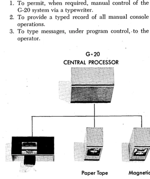
For a small system the central processor may operate a number of accessory devices directly as illustrated in Figure 2 (page 16). Such a system permits the high speed of the central processor to be used at modest cost for engineering and scientific problems requiring min-imum input and output. It is also an effective system for a modest data processing task, in which case much of the time of the processor might be used in the detailed con-trolling and operation of accessory units.
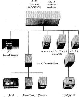
To meet larger requirements the, system may be ex-panded by adding memory to the central processor, by adding more direct computer communication lines, and through the addition of buffer units. Figure 3 (page 17) re-presents a medium scale system in which only an oper-,ators console and high speed control buffer and magnetic tape units are operated directly by the central processor. For larger scale systems the processor may be equipped with additional communication lines. These lines afford direct simultaneous communication with the' processor's memory. In Figure 3 the control buffer units, which are small stored program computer-like devices are each
di-14
IIIIC::::::=". 1111:::::::11
IIIIC!:=~::::::; ~rected by 'the computer to perform a sequence of oper-ations which they can perform with little or no computer assistance, leaving the computer free for other tasks. When a control buffer unit, with its associated sub-system, has completed its assignment or encountered a problem beyond its capability, it may interrupt the central proc-essor, informing it of the status of that part of the oper-ation which it has perfOl;med. This interrupt system, along with ,the real time clock provided in the G-20, permits it
to manage a system including a number of control buffer operated sub-systems efficieIUly.
In addition to on-line operation as described, the con-trol buffer may operate as the center of a variety of off-line systems. In the on-off-line and off-off-line systems the same printer, punched card and tape, and magnetic tape equip-ment are used.
The G-20 system can be used as a scientific computing,
data processing, or business computing system. It has facilities for automatic compilation of programs from algebraic and business oriented languages. In the para-graphs which follow the various system elements' are de-scribed in some detail.
central processor
The G-20 is a high-speed single-address computer with
ma'gnetic core storage and parallel arithmetic. Operations are performed in extended pi-ecision floating-point octal to 14 digits. Two.forms of floating-point storage are avail-able: single precision, equivalent to half the precision of the arithmetic unit, and using one word; or extended precision, the full precision of the arithmetic unit, using two words. A fixed-point mode of operation is available using storage of 9 octal digits. Sixty-three conventional index registers are available and the command structure
permits addressing of almost unlimited flexibility. Thirty-two of the commands can be repeated automatiCally any desired number of times on a sequence of operands. In-put-output simultaneous with computation is available.
The basic central processor contains about 5,000 tran-sistors and 30,000 diodes in addition to one or two mod-ules of core memory containing 4,096 words each. (Addi-tional core memory is in a separate cabinet.) Components are fixed to printed circuit cards mounted on strips. The strips are arranged on hinged panels which swing out to make all parts of the unit easily accessible. The equip-,ment is 66" wide, 28" deep, and 64" high and weighs
2,000 pounds. With 4,096, word memory it requires 2.5 KV A of 115 or 230 volt, single phase, 60 cycle power. Other voltages or frequencies are available on special order.
The minimum core storage supplied for the G-20 data processing system consists of 4,096 words of 32 bits each. Up to 7 additional 4,096 word modules may be added to the basic system to provide a total core memory of 32,768 words, with each word directly addressable.
addressing facilities
The G-20 provides for flexible addressing and indexing without disturbing the contents of the accumulator. A string of numbers and/or addresses is built up in a regis-ter known as the operand assembly regisregis-ter. This string can be used as an operand, or an address, or as the ad-dress of the first term of a new string. The process can be continued indefinitely. This makes possible operands of the forms:
1.
2. 3.
A
+
B+ . .
+
(I)+
(J)+ ..
(A
+
B+ ..
+
(I)+
J)+ .. )
(A
+
B+ .. +
(I)+
(J)+ .. ) +
D
+
E+ .. + (K) +
(L)+ ..
4. ((A
+
B+ .. +
(I)+ 0)+ .. ) +
D
+
E+ .. + (K)+
(L)+ .. )
where A, B, etc. are based addressesI,
J,
etc. are index addresses( ) =
contents ofThe way in which this is accomplished is explained in more detail in the following paragraphs. ,Some elementary ex-amples are also given. A command word in' the G-20 (see Table 1) carries, rin addition to the operation code and flag bits, a 2-bit mode code and two addresses: a base ad-dress A of 15 bits and an index adad-dress I of 6 bits. The mode bits specify the way in which A and I are to be interpreted to form an operand or an operand address. The information can be summarized as shown in Table 2 which indicates
2 7 6
15
I
OP
I
I
mode opcode
index
base address 0
Table 1. Command word
T abl~
2.
Addressing '. modesMode
Action
.~
(OA)-+:A
+(1) X-l: '
(OA)
-+
(A) + (I)
==
X2
((OA) + A -+ (I))
~X'" ,.' " , 3
,,'{(()A),-+(A)+(I»X
where, OA: , operand assembly , register,
.X~oper-and,
'A-:-base ,address,',I= index address,
(.)~con-tents of
'
the manner in which the operand X is formed from the previous contents, if any, of the operand assembly register, combined with the two addresses.
In the simple case where one word is used for a com-mand the initial content of OA will' b~ zero. For t.bis case ' the operand, X, for each of the four modes will be:
o
A+
(I) ~ X1 (A)
+
(I) ~ X2 (A
+
(I»' ~ X 3 ((A)+
(I» ~ XIt can be seen that Mode 2 represents the conventional in-dexed operand address where A is the base address and I one of the 63 index registers. For problems requiring a greater number of indexes, ,any number of words can be combined in one command using as indexes any number of locations situated anywhere in core memory. This flex-ibility is made possible through the use of "preparation" Op codes, which perform address computation, leaving the computed address standing in the operand assembly regis-ter as indicllted by (OA) in Table 2. The symbolic assem-bly routine provided with the equipment selects the num-ber and variety of command words to perform the required addressing. Thus, a command requiring three indexes is written:
CA A
+
(I)+ 0) +
(K)which might mean clear and 'add the term Aijk of a three dimensional array.
operation codes
The operation codes of the G-20 include arithmetic oper-ations, arithmetic tests, logic operoper-ations, logic tests, as well as store, register, index, and transfer control commands. There are also address preparatic;n commands and
input-Figure 1. Representative G·20 data processing system
[image:17.618.322.572.18.199.2] [image:17.618.100.301.362.454.2] [image:17.618.50.571.573.731.2]THE BENDIX G-20
output commands: A repeat command applicable to add/ subtract operations, arithmetic tests, logic operations, and logic tests permits a command to be repeated any number of times on a sequence of operands.
In general, arithmetic commands are automatically car-. ried out in extended precision Hoating-point (14 octal
mantissa plus 2 octal exponent) in the arithmetic unit. The distinction between extended precision and single precision exists only in store commands.
Logic operations are carried out to 32-bit precision and the other bits of the accumulator are cleared. Arithmetic and logic test commands leave the accumulator undis-turbed.
arithmetic
The G-20 performs all arithmetic in integer Hoating-point octal. Numbers have the form of a positive or nega-tive octal integer multiplied by a posinega-tive or neganega-tive in-tegral power of 8. Hardware representation is 3 binary digits for each octal digit of the number. .
The command structure makes available automatic ad-justment of the exponent to a pre-assigned value, or to zero, to facilitate operations in fixed point or in integers.
The arithmetic unit performs aU arithmetic to 14 octals precision and the numbers can be so stored. It is also pos-sible to store automatically the most significant 7 octals, a fixed e~ponent number of· 9 octals, an integer of 9 octals, or an integer of 7 octals.
The maximum range of numbers handled without scaling is:
'. -+- 8-63 to -+- 877 to -+- 10-57 to -+- 1069
approximately. In single precision the upper limit ~s ± 870 or: about± 1063 • A non-biasing round-off rule is applied automatically except in division and "integer" operations, where truncation is used instead.
operating speeds _
Times for representative operations appear in Table 3.
One-Word Precision Extended Precision Fixed Floating Fixed Floating
Point Point Point Point
+
7
13 13 138
13 13 13X
49
49
62 6298
98
78
78
Table 3. Average execution times in microseconds
The accessory units which may be attached to the G-20 system include the control buffers, control consoles, pa-per tape stations, magnetic tape units, card and printer couplers, line printers, and core mempry modules.
control buffer
The control buffer isa stored program computer-like unit employing a 1,024 character magnetic core memory. This memory is used as a store for commands as well as a buffer for input-output data. It connects to two com-munication lines; the computer line and a buffer line as shown in Figure 3. In operation it communicates brieHy with the computer or magnetic tape equipment at high . speed on the computer line and then operates the slower
input-output equipment on its buffer line.
16
The buffer can execute complex programs including conditional transfers of control' based on its own state, interrupt requests it has received, and specific queries it has made of associated uIlits. It -receives and transmib blocks of information and translates character codes at high speed. It receives and transmits interrupt signals which can be used to interlock a multi-element system in the performance of a complex operation.
A representative control buffer operation might be as follows: The G-20 transmits instructions over its com-munication line to the buffer· shown on the left in Figure 3. The control buffer then begins executing th,e instructions which cause it· to switch from the computer communica-tion line to the buffer communicacommunica-tion line. It then in-structs the card reader to read several cards, transmitting the information to the communication line. The buffer re-ceives and stores the information from the cards. It may then translate the punch card codes to a code specified by the central processor, after which it stores the informa-tion in a block on magnetic tape. After repeating this sequence of operations until all cards have been read, the buffer then transmits an interrupt request directly to the central processor indicating completion of the assigned task.
As an example of off-line control buffer operation, con-sider the case of a buffer, a magnetic tape unit, and a . printer at a location remote from the central processor. In this case output tapes prepared by the processor are trans-ported to the remote location. The initial blocks of infor-mation written on the tape may contain instructions to the control buffer for listing the data written on other blocks of the tape, permitting an essentially automatic remote printing operation.
control console
The control console provides the G-:20 operator with the facilities necessary to initiate and control the execution of programs. It has three important functions:
l. To permit, when required, manual control of the G-20 system via a typewriter.
2. To provide a typed record of all manual console operations.
3. To type messages, under program control,. to the oper.ator.
Control Console
G·20
CENTRAL PROCESSOR
Paper Tape
Reader/Punch
Magnetic
[image:18.620.307.547.443.728.2]Tape Unit
Figure 2. Small G-20 system having three accessory units
[image:18.620.42.287.479.571.2]The typewriter keyboard is equipped with 88 charac-ters which provide for the typing of upper and lower case letters, digits, and 26 special characters.
paper tape station
The Bendix paper tape station PT-10 provides punching (Teletype Corp. punch) at 100 characters per second and reading (Digitronics C011p. reader) at 500 characters per second for standard 8-hole paper tape.
magnetic tape system
Any number of (Potter Instrument Co.) tape units may be connected to a computer line or buffer line. Informa-tion is recorded on the tape in blocks formed from char-acters of 8-bits plus parity. One word is, therefore, re-corded as four 8-bit characters. The data transfer rate for reading and writing on tape is 60,000 8-bit characters per second. Individual tape units can move the tape forward or backward
a
specified number of blocks while off-line.It is recommended, but not required, that magnetic tapes be connected to the computer line whether the system contains buffers or not. This gives complete flexibility in the use of magnetic tapes and permits access to any tape by the G-20 or any control buffer. The fmction of com-puter primary line time occupied by transfer of informa-tion to and from magnetic tapes is not the limitainforma-tion in most practical systems. Although the tape can operate with blocks of arbitrary length, to facilitate continuous addressing, information on magnetic tapes is stored in blocks of fixed length. Any block can be written over. The standard block length for which service routines are pro-vided is 512 words or 2,048 characters.· If the recom-mended system is used, each word in G-20 tape library is uniquely addressable and the beginning address of each block is written on the tape at the beginning of the block. The programmer need only specify the tape address he desires and the supervisory routine keeps track of which physical 'tape handler contains the tape reel in question.
card and printer coupler
The card and printer coupler is used to control line printers and 80-column card machines. The coupler, when used to drive an output device, receives information serially by characters and delivers information in parallel to all of the columns of the output device. It is also able to per-form the inverse operation.
Once an input-output function has been initiated, the card and printer coupler controls subsequent transmis-sions until an entire card has been read or punched or a complete line has been printed.
The card coupler is capable of reading and punching cards in three formats. An extended Hollerith code of 256 different characters includes as a subset all of the code configurations which can be produced by a keypunch or read by a tabulator. Row binary and a column binary modes are also available for processing cards using other chamcter representations or for compact information stomge.
When operating a high-speed printer, the coupler is capable of either fixed cycle or so-called free wheeling cycle operation. In this .mode the printing process begins at the completion of any paper feed cycle' without wait-ing for . the character roll to return to a fixed index.
line printers
G-20 (Analex Corp.) printers provide for line-at-a-time printing of numeric or alphanumeric data at rates of from 600 to 1250 lines 'per minute with up to 120 characters
Marchi April 1960
Control Console
G·20 CENTRAL PROCESSOR
Added Memory Modules
G • 20 Control Buffers
[image:19.621.311.574.32.354.2]Card Paper Tape Magnetic High Speed Reader/Punch Reader/Punch Tape Unit Line Printer·
Figure 3. G·20 system showing use of control buffer unit
per line. A continuously revolving print roll carries a num-ber of complete sets of printing characters, each set oc-cupying one circumferential track on the print roll. A line of print is created by driving the 'paper and ribbon against the print roll by means of a set of individually timed ham-mers, one for each print column. Timing of each hammer determin'es the character to be printed in that ~olumn. The paper remains stationary during printing and is upspaced after a complete line has been printed.
The print cycle can begin at any character position and need not begin at the same character for succeeding lines. The standard character set uses a 63-character alphabet.
communication system
The Bendix Digital Communication System is an ap-proach toward organizing all of the components of a com-plex system on a common language basis. The common language understood by all units is a language of 10-bit characters which, in general, mean the same to all units. The first 8 of the 10 bits are coded command or data in-formation. These 8 bits correspond to one character in the buffer, one typewriter character, one character on mag-netic tape, one character on paper tape, or one charac-ter in the G-20. The 8 bits can also represent in card operations one extended Hollerith character, the upper or lower half of a card column (with 2 leading zeros) in col-umn binary, or 8 successive positions in row binary. In-side the G-20, four characters. are combined to form a word, but the decomposition and· recombination of char-acters to G-20 words is automatic. The 9th and 10th bits are data flag and odd parity respectively. The maximum distance permitted"between units in the G-20 communica-tion system is 1,000 feet, dictated by transmission
char-acteristics of the lines. •
Circle 100 on Reader Service Card.
DEKATRON. and DIGITRON
c
0 /d
c a t h o d e
B/A DEKATRON TUBES-Full line of 7 types
High speed (up to 20,000 cps) - Reliable up to 75,000 hours
- low current - can be used to totalize,
sort, program or control - many other versatile
appl ications.
i :
c o u n t i n g
tub
e
s
~
•••.~
'-'.,.
~
i ~ IB/A FULL SIZE DIGITRON GR 10G
Indicates digits 0 through 9. Ideal for use in a remote
readout or indicator panel. B/A VOLTAGE REFERENCE TUBE
GDBS W/S
Useful in high-level stages of DC amplifiers. B/A MINIATURE DIGITRON GR 10W
10 digit direct readout
- simple - compact - long life
.~
'
... '.'k.,J
<.~\\
The most comprelzensive· tube range available featuring. economy,
long-life and versatility.
No jumps in characteristic - constant internal resistance
- minimum anode current 50 p.a.
18
- suitable for miniature remote readout systems. B/A FRACTION DIGITRON GR 4G
Direct readout -~, 1/2, %, May be used to display the
state of count of a ring /'1 i \ \
of 4 cold-cathode or thermionic tubes.
~.'.~.-.--".'. ..~.r+'
~ ~
B/A SIGN DIGITRON GR 2GMay be applied to register the arithmetical operation being followed during random add-subtract counting operations.
The B/A Dekatron and Digitron line is widely distributed in the United States. Write today for the name of your nearest representative and NEW brochure describing specifications and applications.
B/A COMPUTER TRIGGER TUBE GTR 120W
Inexpensive sub-miniature - useful for slow-speed storage - especially designed for computer application.
B/A TETRODE TRIGGER TUBE GTE 175M
a ..
ircl-A'I'onllic, Inc.
33 UNIVERSITY RD., CAMBRIDGE 38, MASS.Circle lOon Reader Service Card.
Emmanuel· ( Bert) Berlant, jormer-ly president oj Berlant Associates, ~
is a pioneer in the magnetic re-cording field. Jl e.headed the firm; which bore his name jrom 1946 until 1955.ln
1956,
when thefirTJl was absorbed by AmericanElec-tronics . and became Berlant· In· .struments, he· remained as director'
for another year.
Between
1943
and1945,
Berlant was. supervisor of the Pictorial En-gineering Research Laboratories, Signal Corps Photographic Center, U.S. Army. Prior to that, he was: director of research and develop- ' ment at Optical Research, Inc., New York City.Berlant, who lives in Southern Calijornia, is a consultant {n the magnetic recording field.
Marchi April 1960
a survey
DIGITAL MAGNETIC TAPE RECOR\DE'RS
by BERT BERLANT, Consultant
On the following two pages, DATAMATION reviews the basic characteristics of reel-'type digital magnetic tape recorders which are primarily designed for the storage and reduction of digital data in computation and digital control systems. Included are commercially available mechanisms with their required read and/or write preamplifiers and the control amplifiers needed for their operation.
Analog reel to reel magnetic tape recorders, drum type recorders, bin type recorders, and special. application recorders are to be covered in surveys now in preparation.
Ease of read and write, high information density and large storage capacity, and reasonably rapid access to desired data are the major factors that have led to widespread use of the reel to reel magnetic tape recorder as a memory bank in digital computers of all kinds. The most commonly used mechanism for this purpose is the high speed shuttle which scans the tape in search of the desired information, located by an address system; then repeatedly re-scans the de-sired block of data until the information has been fully utilized by the com-puting system. The tape mechanism is then directed to search for the next
de-sired block of data by address. .
Control of the mechanisms is achieved by pulses or level change signals transmitted from the computer control center to the mechanism. The various base functions common to virtually all mechanisms in this category are Fast Forward, Forward D11ive, Stop, Reverse Drive, and Fast Reverse. Modes of operation are usually Read or Write. Automatic control and automatic read/ write are usually supplemented by manual control and read/write, with the manual controls located on the mechanism and sometimes duplicated in a
re-mote control panel. .
In addition to these control funcbions, the designs usually incorporate end of tape sensing, operating condition readiness signals, and many interlock re-finements to insure proper operation.
Some basic problems are involved in the design and construction of these high speed digital tape shuttling mechanisms. These include near instantaneous start and stop of the tape. It will be noted from the specifications that the tape goes from standstill to full reading speed within a few milliseconds from re-ception of the "go" signal, and comes to a dead stop in ,the same few milli-seconds from arrival of the "stop" signal, restarts in the ~pposite direction to the beginning of the desired block, stops and again repeats the entire cycle rescanning the data block until the information is no longer required by the sink.
Another problem involves control of the tape storage reels to permit the tape to be supplied and collected to satisfy the near instantaneous high speed start and stop demands without creating excessive stress and strain on the tape itself, and without allowing slack which will result in malfunction. This is achieved by servo-controlled collection and payout controlled from a buffering system interposed between the shuttling mechanism and the spooling mech-anism to give the scanned portion of the tape opportunity to achieve maximum inertial performance independently of the mass of the reels.
These buffering systems fall into two broad types; vacuum buffers, and mechanical buffers. Generally vacuum buffering is found in maximum perform-ance equipment using the highest tape speeds and ma~imum packing density, and mechanical buffering in systems with lesser demands.
The stringent mechanical requirements of these high "speed shuttling oper-ations are not obvious upon casual observation; a little consideration of the tremendous inertial loads imposed upon both shuttling mechanism and spool-ing system to meet the rigorous demands imposed upon these devices will bring a new appreciation of the skill and ingenuity that has gone into their design and construction.
Rack panel mounted or in their own consoles, most of these units were de-signed for computer center conditions and require air condirioned environ-ments with temperature and humidity controlled.
(Information in this survey was compiled from data supplied by the manu-facturers.)
DIGITAL MAGNETIC TAPE RECORDERS
Max. Maximum Metered
Reel Tape Read/Write Rewind Rewind Maximum Size Hub Width Taee Speed Speed Time Tracks POTTER 908 10%" °NAB 1%" 150 300 1% mins. 48
Opt. Hips oOips 2400'
"
906 10%" NAB 1%" 150 300 1% mins. 48Opt. ips ips 2400'
"
910 10%" NAB 1%" 100 225 2% mins. 48Opt. ips ips 2400'
"
3280 10%" NAB 1%" 10 ooooNA 2 mins. 48Opt. ips 2400'
AMPEX FR 300 10%" NAB 1" 150 225 2 mins. 21
Opt. ips ips 2400'
"
FR 400 10%" NAB I" 75 not 2% mins. 21Opt. ips metered 2400'
SHEPARD LABS .. 10%" NAB 1" 200 360 1% mins. 16
IBM ips ips 2400'
FAIRCHILD F-411 10%" NAB I" 75 NA 6 mins. 20
Opt. ips 2400'
D~TAMATIC 10%" Spec. %" 120 360 82.6 secs. 10
ips ips 2400'
NCR 304 10%" NAB %'~ 150 225 2 J!lins. 8
ips ips 2.400'
PHILCO 2000 10%" Spec. I" 120 225 2 mins. 16
ips ips 2400'
RCA 581 10%" NAB
%"
100 100 4.6 mins. 16ips ips 2400'
REMINGTON RAND 10%" Spec. %" 100 100 5 mins. 8
Univac II ips ips 2400'
BURROUGHS 546 10%" NAB
%"
90 120 4% mins. 15ips ips 2500'
"
53368 10%" NAB %" 90 120 4% mins. 15ips ips 2600'
"
551 10%" Spec. %" 120 120 5.83 mins. 12ips ips 3500'
"
544 10%" Spec.%"
60 120 4.2 mins. 12ips ips 2500'
IBM 727 III 10%" Spec. %" 75 not 70 sec. 7
ips metered 2400'
"
729 I 10%" Spec. %" 75 not 70 sec. 7ips metered 2400'
"
729 II 10%" Spec. %" 75 not 70 sec. 7ips metered 2400'
"
729 'III 10%" Spec. 1f2" 112.5 not 40 sec. 7ips metered 2400'
"
729 IV 10%" Spec. %". 112.5 not 40 sec. 7ips metered 2400'
COOK 59 10%" NAB I" 150 225 2 mins. 32
Opt. ips ips 2500'
" 750-7300 8%" Spec. I" 75 120 NA 39
Opt. ips ips
SANGAMO 14" NAB 2" 90 NA 2% mins. 32
ips 2500'
*NAB - NARTB standard hub; Opt. - special hubs or a cable; Spec. - proprietary hub design
**ips - inches per second
For POTTER Information Circle 101. For DATAMATIC Information circle 105.
For AMPEX information circle 102.
For NCR information circle 106. For SHEPARD Information circle 103.
For FAIRCHILD Information circle 104. For PHILCO information circle 107.
Char.
Start Stop Transm. Write
Time Time Buffering Rate Circuitry Method Power 3 1.5 VAC. %" - 45KC oooMod. RZ 115V. 60 cycle ms ms 1" - 90KC S.S. NRZ 15 amperes
3 1.5 MECH. %" - 30KC Mod. RZ 115V. 60· cycle ms ms 1" - 50KC S.S. NRZ 10 amps.
3 1.5 MECH. %" - 18.8KC Mod. RZ 115V. 60 cycle ms ms 1" - 30KC S.S. NRZ 5 amps.
3 1.5 MEGH. NA Mod. RZ 115V AC 60 cycle
ms ms S.S. NRZ 3 amps.
2 1.5 VAC. 1" - 90KC Mod. NRZ 117 AC-50 or 60 cycle
ms ms
Y2" -
45KC S.S. 15 amps.5 5 MECH. 1" - 45KC Mod. NRZ 117 AC-50 or 60 cycle ms ms %" - 22.5KC S.S. 4 amps.
2 2 VAC. 1" - 51.2KC Mixed RZ 220V -3p-60 cycle ms ms %" - 25.6ICC NRZ
5 5 NA NA Tubes RZ 450 watts
ms ms NRZ
3 3.5 VAC. 64 KC Alph. Mod. NRZ N;A. ms ms 96 ICC Dec. S.S.
3 2.5 VAC. 33KC Mod. NRZ 2KVA
ms ms S.S.
8.6 8.6 VAC. 90 KC Mod. NRZ l.024 KVA
ms ms Mixed
25 2 MECH. 33 KC Mod. RZ 1.4 KVA
ms ms S.S. NRZ(Mod)
2-5 2-5 VAC. ·25 KC Tubes RZ 2.2 KVA ms ms
7 7 VAC. Depends on Tubes RZ 115 VAC ± 10 V. ms ms info. format NRZ
7 8 VAC. Depends on Tubes RZ 105-125 VAC, ms ms info. format NRZ 60 cycle, 750 watts
3 3 VAC. 25 KC Mixed NRZ 5.3 KVA ms ms
6.5 6.5 VAC. 60 KC Tubes NRZ l.2 KVA ms ms
10 5 VAC. 15 KC Tubes NRZ 3 p 208V. 6 amps. ms ms
7.5 5 VAC. 15 KC Tubes NRZ 4100 BTV per hour ms ms
7.5 2 VAC. 15 KC S.S. NRZ 3 p 208V-4 amps. ms ms 41 KC
5 2 VAC. 62 KC S.S. NRZ 3 p 208V-4 amps. ms ms
5 2 VAC. 22.5 KC S.S. NRZ 3 p 208V-4 amps. ms ms 62.5 K!C
3 3 MECH. 90 KC Mod. RZ 115V. 60 cycle 500 W.
ms ms S.S. NRZ-RS
3 3 MECH. 45 KC Mod. RZ 115V 60C 400 cps
ms ms S.S. NRZ-RS ± 28 VDC
2 2 NA NA Mod. NA 117V; 60C. 6 amps.
ms ms S.S.
***Mod - modular; 5.5. - solid state; mixed - solid ****NA - No Answer state and tubes
For RCA information circle lOS. For IBM information circle 111. For REMINGTON RAND information circle 109. For COOK Information circle 112 •
For BU~ROUGHS info'rmation circle 110. .For SANGAMO information circle 113.