Design and Buckling Analysis of a Multi-Shell
Blended Wing Body for Interior Floor
Mr. Palash J. Muley1, Mr. M. Sohail Pervez2
1
PG Student, 2Professor, Mechanical Engineering, Anjuman College of engineering and technology, Nagpur, Maharashtra, India.
Abstract: The present paper highlights the basic difference between a conventional aero plane body and a more aesthetic multi-shell blended wing body. The interior structure consist of wall partitions and floor, of which floor design is significantly emphasized in this work. In this paper two relevant structural design aspects are considered for Isotropic materials and composite materials. The modeling and statical buckling analysis of blended wing body is carried out and the results are investigated for the optimum selection of material to be employed in making blended wing body.
Keywords: blended wing body, multi bubble fuselage, Isotropic metal, composite material, angle of orientation.
I. INTRODUCTION
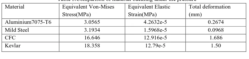
[image:1.612.91.521.533.711.2]The very idea of blended wing body was introduced almost three decades ago wherein the idea was to build a new type aircraft design so that more passengers would be accommodated on the aircraft .The Blended wing body is not fully novel concept because it was considered by Horten, Northrop and other from the mid of 1930 to the mid-1950s. BWB aircraft was previously called tailless airplane and flying wing aircraft [1, 2].After that BWB was reintroduced in the year 1988 by Robert Liebeck [3] at the McDonnell Douglas Corporation. Aeronautics Research Centre Niedersachsen (NFL) in Germany initiates a project Energy System Transformation in Aviation. The project goal is to reduce carbon dioxide emission with the help of this design concept and new technologies and came up with BWB which is most promising technology. BWB is a concept promising advantages in aerodynamic performance as well as in reduction of fuel consumption. Aircraft primary distribution of a load in conventional aircraft Vs a BWB aircraft [5] (fig. 1).Research shows the potential of unconventional aircraft with respect to environmental concerns and noise pollution. Develop the efficient structure concept and leave the constraint of cylindrical pressure vessel of conventional aircraft. Reduction of the maximal bending stress due to the better distribution of the aerodynamic loads relatively other conventional aircraft [6,7] .A higher passenger acceptance of BWB cabins was also found [8]. The design of interior fuselage must resist the internal cabin pressure. Thus to increase structural efficiency, several multi-bubble fuselage concepts were developed. In previous BWB studies [9] effects of cabin shape and volume were investigated from a baseline configuration using an aerodynamic based optimization scheme, but structural design with internal pressure or buckling issues were not addressed. This project investigates the optimum buckling strength of a blended wing body. In this first part paper present design of multi-bubble fuselage segment for a BWB and its interior cabin structure analysis by considering two Iso-tropic metals. Second part of this paper presents an interior cabin structural analysis of BWB by considering two composite materials.
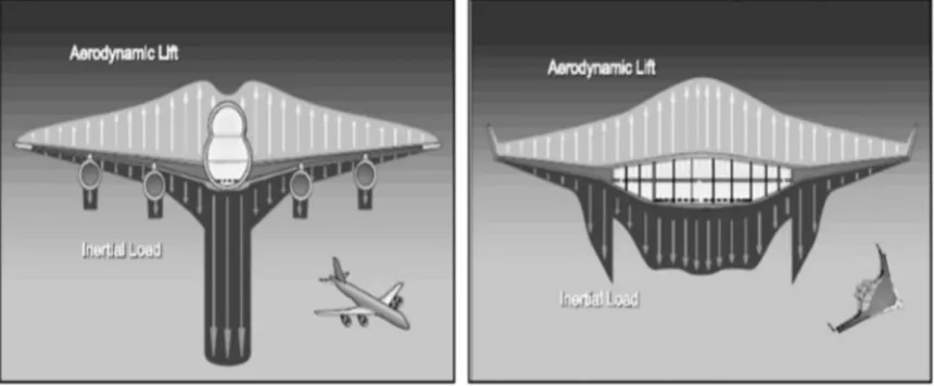
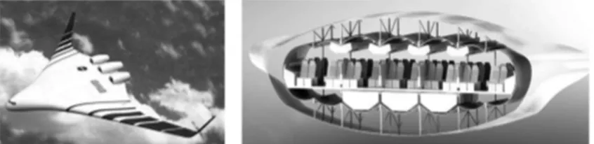
Fig 2: a) Exterior view of NASA BWB. Fig 2: b) multi bubble fuselage cross section concept.
II. LITERATURE REVIEW
Egbert Torenbeek (2016) presented Classical Airplane Concept, Flying Wing and Tailless Aircraft, Aerodynamic and Fuel Efficiency, Very Large Aircraft (VLA), Hybrid Flying Wing, Genesis BWB Aircraft, Evolution of First-Generation BWB, Second-Generation BWB, Challenges and Advantages. Where the BWB study projects have proven that modern advanced design technologies are available to advanced designers to make reliable predictions of essential BWB characteristics like as computational aerodynamics, structural analysis, and flying qualities [4].
Z.Van der voet, F.J.J.M.M Geuskens, et.al.(2012) presented interior Aircraft with a capacity of circa 300 passengers where all gravitational, inertia and aerodynamic loads are carried by the aerodynamic shell & pressurization loads are only carried by the multi- bubble. As a result multi bubble BWB is more efficient in passengers’ transportation than conventional aircraft. Overall it
delivers similar comfort levels to the passengers [5].
VivekMukhopadhyay* (oct-1996) for analysis, two non-cylindrical pressure vessel are selected. One with flat sandwich shell and other is vaulted sandwich shell concept with a honeycomb core. As a results indicate that a double-skin vaulted ribbed shell concept could offer significant weight advantage over a flat ribbed shell concept as well as the both the honeycomb sandwich concepts with similar levels of stresses and deflections [7].
V. Mukhopadhyayn (2005) analyzed structure of BWB for 480 passenger version. Where ybrace fuselage improved to vaulted shell partial multi-bubble type fuselage which has better stress distribution, for same material and dimension [8].
F.J.J.M.M Geuskens, O.KBergsma,S.koussios, et.al. Presented the stresses and deformations induced by pressure. Here the walls of the multi-cylinder and the tapered multi-cylinder are replaced by pillars .The walls in the multi-bubble are not carrying axial stresses, but only the vertical loads. A multi-bubble connected into an aerodynamic shell is a potential solution as a future pressure fuselage for BWB [10].
V. Mukhopadhyay*, J.Sobieszczanski-sobieski, et.al. (2004) finding an efficient noncylindrical BWB configuration, considering
both internal pressure and compressive load including buckling stability. It is found that additional cross-ribbed outer shell structures provide buckling stability and carry span wise bending loads, appear to be quite effective. Thus, it was advantageous to use the inner cylindrical shells for pressure containment and let the outer shells resist overall bending [11].
Majeedbishara,peter horst, et.al. (2018) analyzed new structural BWB fuselage concept by considering laminar flow control and
applying boundary layer suction in order to reduce the aerodynamic drag. As a result the changes in the skin layups do not have a major impact on the maximum stress, the change in frame and rib distances from 1 m to 0.5 m has reduced the maximal stress to 36% and the analysis of linear buckling is increased from 0.82 to 1.26. The fatigue investigations did not indicate a clear advantage of a CFP micro-topology over a conventional interrupted fiber micro-structure for the considered load situations [12].
Ravi Kumar, Ganesh Gupta, Shamili GK, et.al. (2017) presented stiffened and un-stiffened plates with three different types of composite materials. As a result Kevlar yields highest strength and relatively low in deflection [13].
III. METHODOLOGY
The steps involve in design and buckling analysis of multi shell blended wing body are as follows
A. Design synthesis of multi shell bwb structure using conventional method.
B. Selection of Isotropic and Composite materials.
C. Evaluation of static and buckling analysis of multi shell bwb.
D. Selection and optimization of buckling and bending strength for isotropic and composite material.
[image:2.612.106.529.79.182.2]IV. FORMULATION OF PROBLEM
In the literature review of blended wing body, the authors have focused about the exterior part of it and very few papers discus about the interior part of blended wing body but detail is not reported .so for safety of passenger and aircraft. The interior portion of blended wing body must be made such that it should resist the external load as well as internal pressure. Selection of material play important role and hence different material are to be investigated for their properties.
V. MODEL FORMATION
A. Fuselage Segment Model
For the intended purpose of this work, that is, a preliminary design study, the fuselage is represented by a segment in such a fashion like the longitudinal length of 5 m and where a lateral width of 15 m. No particular boundary conditions are applied at the front and back section plane of the segment, thus neglecting any section forces transmitted in longitudinal direction[12].The floor thickness is assume to be 45 mm .
B. Structural Components
Based on the multi-bubble concepts taken a first shell is generated with seven bubbles corresponding to the BWB overall design
[image:3.612.130.495.333.487.2]with seven engines. The middle three bubbles are identical with a diameter of 3.7 m. Thus diameter of the two outer cylinders is decreased in order to adjust the aerodynamic shape of the wing. Figure below shows the geometry of the cross section in the generated multi-bubble cabin. The proposed layout is able to include 20 to 24 seats in on row. The generated 3D cabin-skin is presented in [12]as shown in Figure 4 .
Figure 4:- multi bubble cross section of inner shell with floor.
C. Load and Boundary Condition.
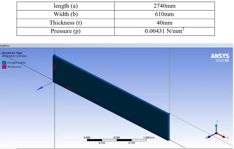
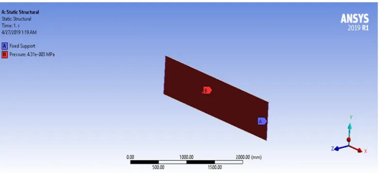
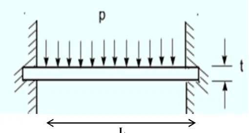
Consider a floor small segment whose width is 610mm , length is 2740mm and assuming thickness is 45mm.where the two edges are fixed with the thin wall. The applied floor pressure includes the weight of passengers, cargo, systems and fuel and it is assumed
to be 0.00431 N/mm2 at the loading case 2.5 g maneuver [12].
L
[image:3.612.181.436.585.721.2]VI. MATERIAL In the bwb the floor material considering two type of materials like:
A. Isotropic materials.
B. Composite materials.
In Isotropic materials taking aluminum7075- T6 ( i.e Aluminum Alloy) and mild steel.
Aluminum7075-T6 normally used in conventional aircraft. While in composite materials taking carbon fiber composite (CFC) and Kevlar .
[image:4.612.130.458.235.294.2]1) Properties of Materials
[image:4.612.134.463.319.485.2]Table 1. Mechanical property of isotropic material [12,18].
Table 2.Mechanical properties of the Carbon fiber and the Kevlar used in the analysis [13].
Material Carbon fiber
composite
Kevlar
E1(Gpa) 164 195
E2(Gpa) 12.8 14.6
E3(Gpa) 12.8 14.6
G12(Gpa) 4.5 7.5
G23(Gpa) 2.5 5
G31(Gpa) 4.5 7.5
V12 .32 .3
V23 .45 .45
V31 .32 .3
Desnsity(kg/ ) 1800 1400
VII.ANALYTICAL CALCULATION OF INTERIOR FLOOR OF BWB IN ANSYS FOR ISOTROPIC MATERIALS. Analytical calculation of bwb interior floor long with explanation was carried out with dimensions. After that, applying pressure load on floor and the deformation was calculated by in order to identify the best design solution with the lowest level of stresses, strain and deformation.
2)
1)
Fig.6. Floor front view (1) and top view (2) .
Material Aluminium7075-T6 Mild steel
E(Gpa) 71.7 200
N .33 .3
[image:4.612.194.415.550.715.2]A. Parameters of interior floor of bwb body are as follows.
length (a) 2740mm
Width (b) 610mm
Thickness (t) 40mm
[image:5.612.119.497.124.366.2]Pressure (p) 0.00431 N/mm2
Fig 7.Geometry of interior floor of bwb in ansys.
[image:5.612.120.498.414.578.2]Fig 9.pressure applied to the floor.
Fig 10. Equivalent Von-Mises Stress of floor for Aluminium 7075-T6.
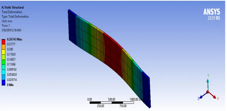
[image:6.612.113.503.484.672.2]Fig.12.Total Deformation of floor for Aluminium 7075-T6.
Fig 13.Equivalent Von-Mises Stress of floor for Mild steel.
[image:7.612.109.507.506.697.2]Fig.15.Total Deformation of floor for Mild steel.
VIII. ANALYTICAL CALCULATION OF INTERIOR FLOOR OF BWB IN ANSYS FOR COMPOSITE MATERIALS.
In the analytical calculation of interior floor of blended wing body for composite material where all layup stacking sequence configuration of floor are taken as [00/900/450/-450]s with equal layer thickness. Where the length is 2740mm and width is 610mm.The stacking sequence and the angle of orientation for carbon fiber composite (CFC) and Kevlar are shown fig 8.1.and fig 8.2 Respectively.
Fig.17. Stacking sequence and the angle of orientation for kevlar
To investigate the effect of fiber orientation angle, the composite plate with layup [0/900/450/-450]s under 0.00431 N/mm2 pressure is considered and the deformation was calculated by in order to identify the best design solution with the lowest level of stresses, strain and deformation.
Fig .20.pressure applied to the floor.
Fig.21.Equivalent Von-Mises Stress of floor for CFC.
[image:10.612.107.507.497.689.2]Fig.23.Total deformation of floor for CFC.
Fig.24.Equivalent Von-Mises Stress of floor for Kevlar
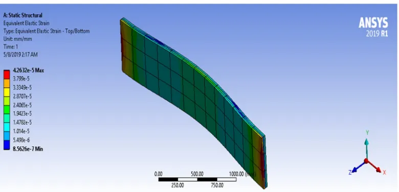
Fig.25.Equivalent Elastic Strain of floor for Kevlar.
IX. COMPARISIONS ON THE BASIS OF ANSYS RESULT.
Table 3.Comparison of material buckling under the pressure
Material Equivalent Von-Mises
Stress(MPa)
Equivalent Elastic Strain(MPa)
Total deformation (mm)
Aluminium7075-T6 3.0565 4.2632e-5 0.2674
Mild Steel 3.1934 1.5968e-5 0.0968
CFC 16.646 12.916e-5 1.686
Kevlar 18.358 12.79e-5 1.50
X. CONCLUSION.
A finite element analysis were conducted to calculate the buckling of interior floor of blended wing body for Isotropic and composite material such as Aluminum7075-T6,Mild steel, CFC, and Kevlar with above mention boundary condition.The whole analysis was conducted using finite element program ANSYS WORKBENCH 2019 R1.As the thickness of floor is increases, the resistance of floor against the high pressure is increases but the weight of floor is also increases. From the table.3.Mild steel have high strength and less deformation than other material but high in density .So for aviation purpose material must be preferred for high strength and light weighted. Thus overall analysis reveals that Kevlar have high strength, relatively low density and less in deformation and hence recommended.
REFERENCES
[1] Crane, Dale .Dictionary of aeronautical Terms, third edition. Newcastle, Washington: aviation supplies & Academics, 1997. ISBN 1-56027-287-2.p. 224. [2] Martinez-Val,R.,FlyingWings.ANewParadigmforCivil Aviation? , ActaPolytechnica, Vol. 47, No. 1, 2007.
[3] Liebeck, R. H., Design of the Blended Wing Body Subsonic Transport, Boeing Co., Huntington Beach, CA, pp. 92–647; also Journal of Aircraft, Vol. 41, No. 1, Jan.–Feb. 2004, pp. 10–25. doi:10.2514/1.9084.
[4] EgbertTorenbeek(2016), Blended-Wing-Body Aircraft: A Historical Perspective.
[5] Z.van Der Voet,Geuskens, F.J.M.M., Ahmed, T.J.,VanEyben, B.N.,Beukers, A. Configuration of the Multibubble Pressure Cabin in Blended Wing Body Aircraft. J. Aircr. 2012, 49, 991–1007.
[6] Liebeck, R.; Page, M.; Rawdon, B. Blended-wing-body subsonic commercial transport. In Proceedings of the 36thAIAAAerospaceSciencesMeetingandExhibit,Reno,NV,USA,12– 15January1998;AmericanInstitute of Aeronautics and Astronautics: Reston, VA, USA, 1998.
[7] Mukhopadhyay, V. Structural concepts study of non-circular fuselage configurations. In Proceedings of the SAE/AIAA World Aviation Congress, Los Angeles, CA, USA, 22–24 October 1996.
[8] Mukhopadhyay, V. Blended wing body (BWB) fuselage structural design for weight reduction. In Proceedings of the 46th AIAA/ASME/ASCE/AHS/ASC Structures, Structural Dynamics and Materials Conference, Austin, TX, USA, 18–21 April 2005; p. 234.
[9] Wakayama, S., and Kroo, I., “The Challenge and Promise of BlendedWingBodyOptimization,”Proceedingsofthe7thAIAASymposiumonMultidisciplinary Analysis andOptimization, AIAA, Reston, VA, Sept. 1998, pp. 239–250; also AIAA Paper 98-4736, Sept. 1998.
[10] F.J.J.M.M. Geuskens, O.K. Bergsma, S. Koussios& A. Beukers,Pressure vessel and Pressure cabin for blended wing body
[11] Analysis, Design, and Optimization of Non-cylindrical Fuselage for Blended-Wing-Body Vehicle.V. Mukhopadhyay*, J. Sobieszczanski-Sobieski** NASA Langley Research Center, Hampton, AIAA 2002-5664.
[12] MajeedBishara, Peter Horst, HineshMadhusoodanan, Martin Brod, BenediktDaum ID and RaimundRolfes.A Structural Design Concept for a Multi-Shell Blended Wing Body with Laminar Flow Control. Received: 15 December 2017; Accepted: 3 February 2018; Published: 7 February 2018.
[13] Ravi Kumar, Ganesh Gupta, Shamili GK ,Anitha D.(2017),Linear Buckling Analysis and Comparative Study of Unstiffened and Stiffened Composite Plate. [14] Multi-disciplinary Design of Aircraft Fuselage Structures,Michel van Tooren 1 and Lars Krakers.2 Delft University of Technology, The Netherlands. [15] Niu, M. C. Y.,"Airframe Structural Design," Conmilit Press Ltd., Hong Kong, 1993, pp. 376-428.
[16] Liu, Y.; Elham, A.; Horst, P.; Hepperle, M. Exploring Vehicle Level Benefits of Revolutionary Technology Progress via Aircraft Design and Optimization. Energies 2018, 11, 166.
![Table 1. Mechanical property of isotropic material [12,18].](https://thumb-us.123doks.com/thumbv2/123dok_us/1239650.649840/4.612.194.415.550.715/table-mechanical-property-isotropic-material.webp)