Four-zone reflective polarization conversion plate
A.G. Nalimov
a,b, S.S. Stafeev*
a,b, L, O’Faolain
c, V.V. Kotlyar
a,ba
Image Processing Systems Institute of the RAS, 151 Molodogvardeyskaya st., Samara, Russia
443001;
bSamara State Aerospace University, 34 Moskovskoye shosse, Samara, Russia, 443086;
c
School of Physics and Astronomy of the University of St. Andrews, North Haugh, St. Andrews,
KY16 9SS, Scotland, UK
ABSTRACT
Binary diffraction optical element was designed for polarization conversion from linear to radial. A grating period was equal to 400 nm, a relief height was equal to 110 nm. Simulation by FDTD method and Rayleight-Zommerfeld integral shown that there are radial polarized light beam in the far field with smooth angle dependence on the beam circle observation position. It was shown experimentally, that a gaussian laser beam with wavelength of 633 nm reflected from the polarization conversion plate contain a radially polarized light.
Keywords: radial polarization, subwavelength grating, polarization converter
1. INTRODUCTION
The use of subwavelength diffractive gratings for manipulation with polarization of laser light was introduced in [1] for the first time. In [2-3] subwavelength diffractive gratings was used for conversion of polarization. When linearly polarized light reflected from this grating it rotates depending of an angle between incident light polarization and directions of grating grooves. Circularly polarized laser light with wavelength of 10.6 um was converted to azimuthally polarized light using binary subwavelength diffractive grating with curved grooves and varying period in [2]. The period of grating was varying from 2 um to 3 um, radius was equal to 9.6 mm. In [3] phase grating converted left circularly polarized light to radially polarized light and right polarized light to azimuthally polarized light. Grating was manufactured in GaAs substrate (index of refraction equal to n = 3.13); grating had diameter of 10 mm, period was varying from 2 mm to 3 mm, relief height was equal to 2.5 um, wavelength was equal to 10.6 um. In [4,5] grating proposed in [3] was upgraded. This grating converts laser light with circular polarization to radially polarized light with high efficiency. Polarization converter for near infrared light (with wavelength of 1.064 um) was investigated in [6]. In [6] also a binary subwavelength grating was used. The grating had diameter of 1 mm, period of 240 nm, relief depth of 470 nm. The grating converts linearly polarized laser light to radially polarized light. In ref. [2-6] proposed elements transmit light to convert it.
In our research we propose a reflective four-zone binary subwavelength micrograting for visible light conversion from linear polarization to radial polarization. [7]
2. DESIGN OF CONVERSION PLATE
In our numerical simulation we used FDTD-method implemented in FullWave (http://optics.synopsys.com/rsoft/). Gold was used as a material of the proposed diffractive optical element (DOE). Figure 1 shows the directions of polarizations of incident and reflected from DOE light.
*[email protected]; ipsi.smr.ru
Saratov Fall Meeting 2014: Optical Technologies in Biophysics and Medicine XVI; Laser Physics and Photonics XVI; and Computational Biophysics, E. A. Genina, V. L. Derbov, K. V. Larin, D. E. Postnov, V. V. Tuchin, Eds., Proc. of SPIE
Vol. 9448, 94482E · © 2015 SPIE · CCC code: 1605-7422/15/$18 · doi: 10.1117/12.2180028
Proc. of SPIE Vol. 9448 94482E-1
180
135
90
45 -e
0
0 10 20 30 40 50 60 70 80 90
a
EI2 o.s
0.6
0.4
0.2
-0 7
0 10 20 30 40 50 60 70
[image:2.612.225.387.90.263.2]a
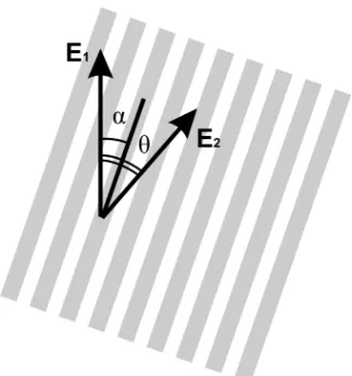
Figure 1. Directions of polarizations of incident E1 and reflected from DOE E2 light
On fig.1 α is an angle between polarization of incident light and direction of gratings grooves, θ is an angle between polarization of incident light and the light reflected from the DOE. E1 is the incident electric field vector; E2 is the
[image:2.612.206.408.352.480.2]reflected electric field vector. Fig. 2 shows the polarization angle of reflected light θ as a function of incident polarization angle α for a grating with height of h = 110 nm, produced in gold film (index of refraction for wavelength of λ=633 nm was equal to n=0,312+3,17i). Period of DOE was equal to 0.4 um.
[image:2.612.211.400.552.670.2]Figure 2. Polarization angle of reflected light θ as a function of incident polarization angle α
Figure 2 shows that angle θ varies from 0 to 180° when angle α varies from 0 to 90°. In other words through manipulation of directions of grating grooves it could be possible to form any polarization. Fig. 3 shows the intensity of reflected light |E|2 as a function of incident polarization angle α.
Figure 3. Intensity of reflected light |E|2 as a function of incident polarization angle α
Proc. of SPIE Vol. 9448 94482E-2
Intensity of refracted light strongly depends from angle α. To decrease the difference between intensities of light refracted from different parts of element designed DOE was divided onto 4 parts. All parts have similar index of reflection.Polarization angles θ was equal to -135°, -45°, 45°, 135°, angles of grating grooves α was equal to -70°, -40°, 40°, 70°,consequently.Figure 4 shows the sketch of designed structure.
Figure 4. Sketch of designed DOE (grating-polarizer)
3. NUMERICAL MODELING
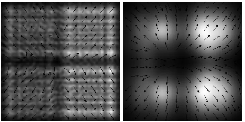
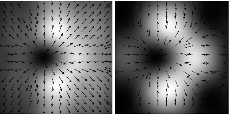
Figure 7 shows intensity and polarization of refracted light on the different distances from the designed polarizer.
Proc. of SPIE Vol. 9448 94482E-3
[image:3.612.104.511.405.608.2]0.75
0.5
0.25
- along OX
- - along OY
Nq'--1
-0.5 0 0.5 1
R (um)
-0.5 0 0.5
[image:4.612.106.509.74.275.2]R (um)
Figure 5. Intensity and polarization of reflected light at the distances z: equal to а) 5.2 um, b) 100 um, c) 200 um, d) 10 mm. The image size is 20x20 um (a-b) and 800x800 um (c)
To estimate the effectiveness of focusing light we numerically simulate the focusing of light using binary microaxicon with period of T = λ at a distance of λ/2 from its surface.The refraction of light from DOE was simulated using FDTD-method, then using Rayleigh-Sommerfeld integral we calculate a light field distribution at a distance of z = 200 nm from the DOE. Propagation of light through the subwalength axicon was calculated using FDTD-method. Axicon has refractive index of to n = 1.5, and relief height of h = 1.266 um. Substrate was not taken into account (axicon rings was located in free space). Figure 6 shows intensity distribution in focal point of the axicon.
Figure 6. Focal point sections obtained by the focusing of linearly polarized light (a) and radially polarized light reflected from conversion plate (b) at the distance of λ/2 from the axicon
Focused linearly polarized plane wave forms elliptical focal spot with diameters equal to FWHMх = 0.64λ and FWHMy = 0.305λ along axes X and Y. Radially polarized light refracted from designed DOE forms focal spot with
diameters equal to FWHMх = 0.407λ and FWHМy = 0.351λ. Both diameters of this focal spot are bellow the diffraction
limit of FWHM = 0,51λ. Despite the drawbacks of design (different index of refraction from each zone) our DOE forms a beam that is different from linearly polarized beam and could be used for tight focusing or superresolution.
4. MANUFACTURING AND EXPERIMENT
To manufacture polarization converter a gold layer with thickness of 160-180 nm was coated on a glass substrate. Then gold layer was covered with resist. Mask of four-zone polarization converter was projected on a resist using electron beam. The element was etched in xylene, which dissolves resist exposed by the electron beam. Using an ion etching mask was transformed into a gold layer. Finally resist were removed using oxygen plasma. The height of manufactured DOE was about 110 nm. Figure 9 shows the SEM image of a central part of designed grating-polarizer. The size of manufactured polarizer was 100x100 um.
Proc. of SPIE Vol. 9448 94482E-4
[image:4.612.96.519.382.493.2]CCD
P2
0
BS
I
%M1III
"
1r r
1
r1%
,,
M2
11a3ep
v
,qO3 [image:5.612.195.419.71.237.2]P1 ND
Figure 7. Image (13х13 um) of four zone polarization converter with period of 400 nm and relief depth of 110-120 nm
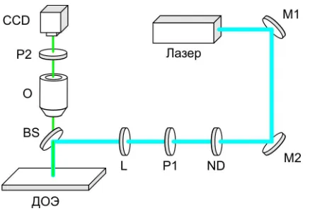
[image:5.612.199.418.342.491.2]Using optical scheme depicted at figure 8 we experimentally obtained radially polarized light when we detected laser light with wavelength of 633 nm reflected from 4-zone DOE. Light from He-Ne laser (with wavelength of 633 nm) propagates through a neutral density filter ND and polarizer P1, then focused by a lens with long focal length L (f = 25 cm) and a beam splitter cube on a substrate with four-zone polarization converters. Light reflected from four-zone polarization converter propagates through beam splitter cube BS and 10x objective O, and then was registered by CCD camera. Polarizer P2 located between objective O and CCD-camera could block a light of incident beam reflected from mirror surface surround four-zone conversion plate.
Figure 8. Optical scheme. M1, M2 – mirrors, ND – neutral density filter, P1, P2 – polarizers, L – lens with focal length of f = 25 cm, BS – beam splitter cube, DOE – substrate with four zone conversion plate, O – 10x objective
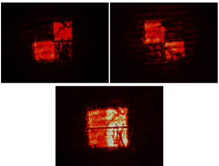
Figure 9 shows an image of four-zone conversion plate when an angle between an axis of output polarizer an horizontal axis is equal to 45° (a), 135° (b) and 90° (c). Incident light was linearly polarized in horizontal direction. This experiment confirm that our 4-zone plate convert polarization of light.
Proc. of SPIE Vol. 9448 94482E-5
Figure 9. Image of conversion plate when the angle between output polarizer and horizontal axis equals to (a) 45 degree, (b) 135 degree, and (c) 90 degree
5. CONCLUSION
A four zone subwavelength binary diffraction optical microelement (size of 100x100 mkm) for polarization conversion from linear to radial was calculated and designed. A grating period was equal to 400 nm; element was manufactured for a wavelength of 633 nm in a gold film with height of 110 nm. Simulation by FDTD method and Rayleight-Zommerfeld integral and experiment shown, that there is a radial polarized light beam in reflected light.
ACKNOWLEDGMENT
The work was partially funded by the Russian Foundation Basic Research grants ## 13-07-97008, 07-31092, and 14-07-97039, the Russian Federation Presidential grant for state support of young Russian scientists with Candidate's degree MK-4816.2014.2, and the Russian Federation Presidential grant for state support of young Russian scientists with Doctor’s degree MD-1929.2013.2.
REFERENCES
[1] Kotlyar, V.V., Zalyalov, O.K., “Design of diffractive optical elements modulating polarization,” Optik 103(3) 125-130 (1996).
[2] Bozom, Z., Kleiner, V., Hasman, E., “Pancharatnam-Berry phase in space-variant polarization-state manipulations with subwavelengtn gratings,” Opt. Lett. 26(18) 1424-1426 (2001).
Proc. of SPIE Vol. 9448 94482E-6
[3] Bozom, Z., Biener, G., Kleiner, V., Hasman, E., “Radially and azimutally polarized beams generated by space-variant dielectric subwavelength gratings,” Opt. Lett. 27(5) 285-287 (2002).
[4] Niv, A., Biener, G., Kleiner, V., Hasman, E., “Formation of linearly polarized light with axial symmetry by use of space-variant subwavelength gratings,” Opt. Lett. 28(7) 510-512 (2003).
[5] Levy, U., Tsai, C.H., Pang, L., Fainman, Y., “Engineering space-variant inhomogeneous media for polarization control,” Opt. Letters, 29(15) 1718-1720 (2004).
[6] Lerman, G.M., Levy, U., “Generation of a radially polarized light beam using space-variant subwavelength gratings at 1064 nm,” Opt. Lett. 33(23) 2782-2784 (2008).
[7] Nalimov, A.G., O'Faolain, L., Stafeev, S.S., Shanina, M.I., Kotlyar, V.V., “Reflected four-zones subwavelenghth mictooptics element for polarization conversion from linear to radial,” Computer Optics, 38(2) 229-236 (2014).
Proc. of SPIE Vol. 9448 94482E-7