DOI: 10.4236/ojfd.2019.94019 Oct. 30, 2019 292 Open Journal of Fluid Dynamics
Tomasz Staśko, Sławomir Dykas
, Mirosław Majkut, Krystian Smołka
Silesian University of Technology, Institute of Power Engineering and Turbomachinery, Gliwice, Poland
Abstract
In this work, the cycloidal rotor fan (CRF) performance was estimated by means of a numerical method based on Unsteady Reynolds Averaged Navi-er-Stokes equations (URANS). The fan with a cycloidal rotor belongs to the positive displacement machines of the rotary type. The numerical algorithm for simulation of the flow in the cycloidal rotor as well as postprocessing of the CFD results was prepared using Ansys CFX CEL. The methodology for the assessment of the CRF performance was proposed and verified. It was found out that the CRF performance strongly depends on the shape of the profile of the applied rotor blade. The NACA 0012 and CLARK Y profiles were tested for the same CRF structure and flow conditions. Also, the crucial importance for the CRF performance has the range of the blade pitch angle change.
Keywords
Cycloidal Rotor, Computational Fluid Dynamics, Fan, Performance
1. Introduction
The application of the cycloidal rotor idea to the fans is not known so far. For the time, being the most widespread application of cycloidal rotors is for ship propulsion and control but the origin of the cycloidal rotor relates to the aero-nautic domain [1][2][3]. Cycloidal rotor is an attractive propulsion system for a wide range of aircraft applications. This type of propulsion system has very good maneuverability for various flight conditions, including hovering, and is mainly dedicated to vertical take-off and landing (VTOL) aircrafts [1] [4]. It was ex-perimentally proved that besides good aerodynamic performance the cycloidal rotor produces little aerodynamic noise, what may be promising in terms to use it for fans. So far several analytical models were developed [4][5][6] which
to-How to cite this paper: Staśko, T., Dykas, S., Majkut, M. and Smołka, K. (2019) An At-tempt to Evaluate the Cycloidal Rotor Fan Performance. Open Journal of Fluid Dynam-ics, 9, 292-302.
https://doi.org/10.4236/ojfd.2019.94019
Received: August 30, 2019 Accepted: October 27, 2019 Published: October 30, 2019
Copyright © 2019 by author(s) and Scientific Research Publishing Inc. This work is licensed under the Creative Commons Attribution International License (CC BY 4.0).
DOI: 10.4236/ojfd.2019.94019 293 Open Journal of Fluid Dynamics
gether with experimental investigations were helpful in design process of cyc-loidal rotors. However, currently, the Computational Fluid Dynamics (CFD) al-lows to take into account unsteady phenomena and it is willingly used in design and analysis of the operation of the cycloidal rotor of various configurations [7] [8][9][10].
The cycloidal rotor fan (CRF), like other cycloidal rotor applications, consists of several blades that describe the cycloidal path rotating about an axis perpen-dicular to the flow direction. The implementation of the cycloidal rotor for fans was numerically and experimentally investigated by authors in former works [7] [8]. The effectiveness of the elaborated CFD model was positively verified by experimental research using LDA measurements [8]. From the point of view of a positive displacement machine of the rotary type, the most effective design is the CRF with four blades. It presents a compromise between preserving a low oscil-lation of the flow stream, the complexity of the design and required rotational speed.
In the presented work the elaborated CFD algorithm for modelling the flow in the cycloidal rotor fan was used in order to estimate the performance character-istics of this type of machine. Also, it was investigated the influence of the blade profile shape on the CRF performance, the NACA 0012 and CLARK Y profiles were tested. Additionally, it was attempted to find the optimal blade pitch angle for the given rotational speed of the rotor.
2. Physical and Numerical Model
The cycloidal rotor fan (CRF), in contradiction to typical cross-flow fan, has no diffuser and its rotor generates the flow in any specified direction. It is possible by changing the blade pitch angle, α, of each blade individually during the rotor rotation with constant angular velocity, ω (Figure 1). The change of the blade pitch angle from the positive value to the negative one during rotation makes possible to work each blade both as a puller or pusher, depending on the blade position angle, γ. For considered here cycloidal rotor, the top blade has initial position with a maximum value of blade pitch angle. During the anticlockwise rotation with 90˚, the blade pitch angle decreases to the zero value. After further 90˚, the blade pitch angle takes a negative value of maximal blade pitch angle. After the next 90˚, the blade pitch angle has again zero value and during the last quarter of rotation, the blade returns to the initial position. The flow direction in such fan can be easily changed by setting the arbitrary initial position of the blades pitch angles. The number of the blades in the proposed design is depen-dent on the ratio of the chord of the rotor blade, c, and rotor radius, R. In the presented design, the blade chord was 50 mm and the radius was 70 mm. For the value c/R in the range of ~0.25 - 1.00, the maximum number of blades is four
[11] (see Figure 1).
DOI: 10.4236/ojfd.2019.94019 294 Open Journal of Fluid Dynamics
Figure 1. Scheme of the cycloidal rotor fan with four blades of the NACA0012 profiles
[8].
DOI: 10.4236/ojfd.2019.94019 295 Open Journal of Fluid Dynamics
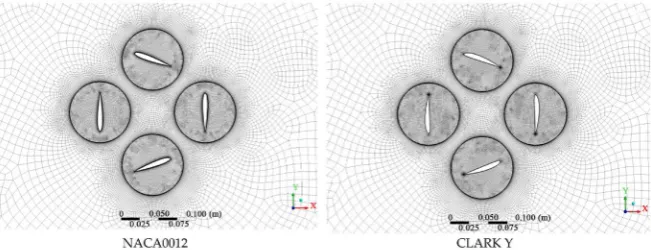
Figure 2. The part of the numerical meshes for CRF with NACA 0012 and CLARK Y
blade profiles.
The transient calculations were performed with constant time step calculated on the basis of angular velocity:
2
t n
ω π
∆ = (1)
where n is the constant used for keeping the similar time step value for numeri-cal simulations with various angular speed, ω.
An increment of the blade pitch angle in certain time step was calculated ac-cording to the relation [7]:
(
)
(
)
0 sin 2 2 sin t t t ω γ α α ω ω γ ⋅ ⋅ ⋅ ∆ ∆ ⋅ + ⋅ =π + (2)
It can be seen from relation (2) that ∆α may have a positive or negative
value what ensures the return of the blade pitch angle to the initial position after full rotor rotation (2π).
3. Cycloidal Rotor Fan Performance Estimation
Let us assume that useful power (Pu) is the power transmitted by the machine
(fan) to the working medium (air), and it may be calculated from the relation:
0 u
P = ⋅ ∆V p (3)
where V is a volume flow rate of the air and ∆p0 represents an increase of
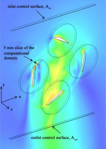
the total pressure between the fan outlet and inlet. For calculations of the volume flow rate for the open rotor fan, it was necessary to assume some outlet control surface, Aout (Figure 3). On this surface, the flow velocity, as well as total
pres-sure, were averaged. It has to be emphasized that such an assumption may lead to small inaccuracy in the power determination of the analysed herein cycloidal rotor fan. Therefore, it was decided to find another way for power calculation.
Another available method for determining fan power is to calculate its me-chanical power (Pm) which results from the product of torque (M) and angular
velocity (ω):
m
P =M⋅ω (4)
DOI: 10.4236/ojfd.2019.94019 296 Open Journal of Fluid Dynamics
Figure 3. A part of the computational domain with marked surface assumed for deter-mination of the volume flow rate.
the individual blades whereas, the torque of the individual blade is determined as a mean value from the full one rotation.
Because the available value of the torque in Ansys CFX CEL led to wrong re-sults it was decided to write an own expression. As we know the torque is the cross product of a force and a length
= ×
M F r (5)
where, F is a force vector and r is a length vector, directed from the centre
of rotation to the force point. According to the assumed Cartesian coordinate system, the considered fan rotates due to the positive torque acting in the
z-direction:
(
)
z = Fx⋅y−Fy⋅ ⋅x
M k (6)
where Fx =
∫
(
τ
x +N px)
dA and accordingly Fy =∫
(
τ
y +N py)
dA. N standsfor a normal vector to the corresponding surface.
Finally, mechanical power was estimated from the quotient of the torque and required time for one full rotation of the fanmultiplied by the constant factor 2π. It had to be done in this way because all CFD simulations were carried out as a transient calculation and any instantaneous values gave wrong results.
DOI: 10.4236/ojfd.2019.94019 297 Open Journal of Fluid Dynamics
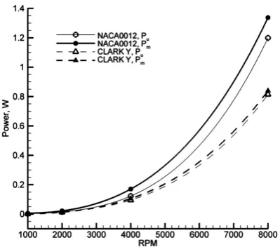
Figure 4. Comparison of the cycloidal rotor fan power for NACA0012 and CLARK Y profiles for different rotational speed, αmax = ±20˚.
blade span. It means that e.g. for the CRF of 50 cm blade span its power will be approximately 100 times higher. The CFD calculations were performed for the blade pitch angle range of change ±20˚ and for the rotational speed of 1000, 2000, 4000 and 8000 RMP. The obtained results were extrapolated by using polynomials of the third order. One can see that the power generated by CRF with NACA 0012 profile is higher than the power of CRF with CLARK Y profile, and for 8000 RPM the power is even two times higher. The CRF with NACA 0012 airfoil generates the volume flow rate (power) by means of both lift and drag forces. Whereas, CRF with CLARK Y airfoil is almost purely lift-type rotary positive displacement machine. The value of mechanical power is higher than the useful power for all presented cases. However, the differences between the useful and mechanical power for CRF with NACA 0012 blade profile are much higher than for the case with CALRK Y profile. It may suggest that the CRF with NACA 0012 is less efficient.
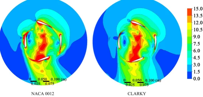
Figure 5 shows the velocity distributions for the CRF with NACA 0012 and CLARK Y profiles for 4000 RPM. One can observe a significant flow separation around the NACA 0012 profiles, what was already observed in previous works
[7][8]. Whereas, the velocity distribution for CRF with CLARK Y profile does not repeat such behaviour, no significant separations around blades are ob-served. Another important difference in flow field for CRF with both blade pro-files is the direction and width of the outlet stream. For CRF with CLARK Y blade profile, the flow is more vertical whereas with NACA 0012 the flow stream leans according to the direction of rotation.
DOI: 10.4236/ojfd.2019.94019 298 Open Journal of Fluid Dynamics
Figure 5. Comparison of the velocity magnitude field for the cycloidal rotor fan for 4000 RPM (v = 0 ÷ 15 m/s, Δv = 1.5 m/s), αmax = ±20˚.
is given to the fluid. Figure 6 presents the comparison of the useful and me-chanical power ratio for CRF with NACA 0012 and CLARK Y blade profiles. One has to bear in mind that the determination of the useful and mechanical power on the basis of CFD results is very sensitive to the many parameters, es-pecially for transient simulation. It can be seen that the CRF with CLARK Y blade profile is much efficient than this with NACA 0012 blade profile, even though it generates less power.
Another possibility for estimation of the CRF performance is to apply the definition of the propulsive efficiency, which is defined as follows:
2
1 u
p
o t in
v v η
+
= (7)
where vout and vin are mean velocities at the outlet and inlet, respectively,
calcu-lated on the control surfaces (Figure 3). The results of the calculated propulsive efficiency are included in Figure 7. One can conclude that also in this case the CRF with CLARK Y profile has higher efficiency for entire range of rotational speed and we may see that both characteristic curves are almost flat.
However, whereas the CRF was applied for the work mode in a duct, the pulsive efficiency rises rapidly. For the 4000 RPM for CRF with CLARK Y pro-file, this value rises to the 0.94, from 0.63 for the open rotor mode (Figure 7).
In Figure 8 the velocity field for the CRF built-up in the straight duct is pre-sented. It can be easily concluded, that this type of fan is preferred rather to work as a puller than as a pusher. The velocity field at the CRF outlet is much less regular than in the inlet part. Application of the CRF to the ductwork is very promising, especially for the ducts of the “very” rectangular shape, where the transition from a rectangular to circular shape is very difficult to manufacture.
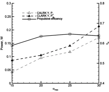
CRF performance also depends on the value of the maximal blade pitch angle,
αmax. It means that the air volume flow rate can be regulated by both rotational
DOI: 10.4236/ojfd.2019.94019 299 Open Journal of Fluid Dynamics
[image:8.595.284.460.279.429.2]Figure 6. Comparison of the useful and mechanical power ratio for CRF with NACA0012 and CLARK Y blade profiles, αmax = ±20˚.
Figure 7. Comparison of the propulsive efficiency of the CRF with NACA0012 and CLARK Y blade profiles, αmax = ±20˚.
[image:8.595.211.541.476.694.2]DOI: 10.4236/ojfd.2019.94019 300 Open Journal of Fluid Dynamics
Figure 9. Velocity magnitude field for the cycloidal rotor fan with CLARK Y profile for 4000 RPM and different αmax (v = 0 ÷ 15 m/s, Δv = 1.5 m/s).
[image:9.595.282.464.543.696.2]DOI: 10.4236/ojfd.2019.94019 301 Open Journal of Fluid Dynamics
doubling the value of blade pitch angle we may increase the power of the CRF about two times.
The characteristic of the propulsive efficiency vs. maximal blade pitch angle is in this case almost flat, similarly, like for the variable value of rotational speed.
4. Conclusions
The numerical analysis of the flow in cycloidal rotor fan (CRF) for two shapes of the blades, with NACA0012 and CLARK Y profiles, was performed by means of Ansys CFX CFD software. The transient analysis was made for four rotational speeds and values of maximal blade pitch angle in order to determine CRF per-formance characteristic. On the basis of the carried out CFD simulations, the following conclusion may be drawn:
− By estimation of the torques and forces in Ansys CFX, the implementation of the own expressions is recommended.
− It was extremely difficult to obtain quantitative information from CFD cal-culations of the flow in cycloidal rotor fan.
− Definition of the useful and mechanical power ratio may be used for estima-tion of the CRF performance as well as the propulsive efficiency, and be an alternative for polytropic and isentropic efficiency.
− The shape of the blade profile affects significantly the performance charac-teristic of a cycloidal rotor fan. The CRF with CLARK Y blade profile works more as a lift-type rotary positive displacement machine, which provides it with higher efficiency.
− The useful power calculated for the CRF with open rotor and for CRF build-up in straight ducts differs from each other less than 3%, for the same working conditions.
− The CRF may efficiently work as a puller fan for ducts of the rectangular shape of the cross-section. The proposed design of CRF is well scalable to arbitrary duct cross-section, especially for the cases of large ratio of width to height of the cross-section.
− The higher value of the maximal blade pitch angle the higher power, but the choice of αmax should take into account the maximum efficiency of CRF.
− For the cycloidal rotor fan (CRF), all three laws valid for dynamic fans are preserved, i.e.
2 3
2 2 2 2 2 2
1 1 1 1 1
1
, , ,
V RPM p RPM P RPM
RPM p RPM P RPM
V ∆ ≅ ≅ ≅ ∆
but one can constitute an additional ones relating to CRF radius and a blade pitch angle
2
max,2
2 2 2
1 1 max,1
1
, .
V R P
R P V α α ≅ ≅
DOI: 10.4236/ojfd.2019.94019 302 Open Journal of Fluid Dynamics
per.
References
[1] Benedict, M. (2010) Fundamental Understanding of the Cycloidal-Rotor Concept for Micro Air Vehicle Applications. PhD, University of Maryland, College Park. https://doi.org/10.4050/JAHS.55.022002
[2] Kirsten, F.K. (1928) Cycloidal Propulsion Applied to Aircraft. Transactions of the American Society of Mechanical Engineers, 50, 25-47.
[3] Wheatley, J.B. (1933) Simplified Aerodynamic Analysis of the Cyclogiro Rotat-ing-Wing System. Technical Notes NACA, No. 467.
[4] Xisto, C., Leger, J., Páscoa, J., et al. (2016) Parametric Analysis of a Large-Scale Cycloidal Rotor in Hovering Conditions. Journal of Aerospace Engineering, 30. https://doi.org/10.1061/(ASCE)AS.1943-5525.0000658
[5] Leger, J., Pascoa, J. and Xisto, C. (2013) Parametric Design of Cycloidal Rotor Thrus-ters. Proceedings of ASME International Mechanical Engineering Congress and Exposition, San Diego, 15-21 November 2013, IMECE2013-65238.
[6] Leger, J., Pascoa, J. and Xisto, C. (2013) Analytical Modeling of a Cyclorotor in Forward Flight. SAE 2013 AeroTech Congress & Exhibition, Montréal, 24-26 Sep-tember 2013, 1-10. https://dx.doi.org/10.4271/2013-01-2271
[7] Dykas, S., Majkut, M., Smołka, K., Strozik, M., Chmielniak, T. and Staśko, T. (2018) Numerical and Experimental Investigation of the Fan with Cycloidal Rotor. Me-chanics and Mechanical Engineering, 22, 25-32.
[8] Dykas, S., Majkut, M., Smołka, K., Strozik, M. and Staśko, T. (2018) Aerodynamic Assessment of the Cycloidal Rotor Fan. Journal of Physics: Conference Series, 1101, Article ID: 012006. https://doi.org/10.1088/1742-6596/1101/1/012006
[9] Siegel, S., Seidel, J., Cohen, K. and McLaughlin, T. (2007) A Cycloidal Propeller Us-ing Dynamic Lift. 37th AIAA Fluid Dynamics Conference and Exhibit, Miami, AIAA2007-4232. https://doi.org/10.2514/6.2007-4232
[10] Sirohi, J., Parsons, E. and Chopra, I. (2007) Hover Performance of a Cycloidal Rotor for a Micro Air Vehicle. Journal of the American Helicopter Society, 52, 263-279. https://doi.org/10.4050/JAHS.52.263
![Figure 1. Scheme of the cycloidal rotor fan with four blades of the NACA0012 profiles [8]](https://thumb-us.123doks.com/thumbv2/123dok_us/8925129.391133/3.595.211.526.77.410/figure-scheme-cycloidal-rotor-fan-blades-naca-profiles.webp)