In situ Tailored Nickel Nano-catalyst Layer for
Internal Reforming Hydrocarbon Fueled SOFCs
Jae-ha Myung, Dragos Neagu, Mark Tham and John T.S. Irvine
School of Chemistry, University of St Andrews, St Andrews, Fife, KY16 9ST, UK
Conventional Ni cermet anodes suffer from carbon deposition when they are directly used with hydrocarbon fuels due to the negative effects of pyrolysis and Boudouard reactions. In this work, the use of a non-stoichiometric perovskite, La0.8Ce0.1Ni0.4Ti0.6O3, as a reforming layer in reducing atmospheres led to the surface being highly populated with homogeneously exsolved Ni nano particles. This catalyst layer was applied to Ni-GDC anode supported and ScSZ electrolyte supported cells to prevent carbon deposition and to stabilize operation with dry methane. The catalyst layer showed both excellent attachment to the Ni-GDC anode and resistance to carbon deposition. The performance of the Ni–GDC anode-supported cells with the catalyst layer was about
1.1 W/cm2 in hydrogen fuel which is similar to that seen without
the use of a catalyst layer. For the ScSZ electrolyte supported cells, the catalyst layer improved the power density and stability when in operation with dry methane.
Introduction
Solid oxide fuel cells (SOFCs) are one of the most promising power generation systems because they are highly efficient, pollution-free and are able to directly convert the chemical energy into electrical energy (1-3). The state-of-the art commercial SOFCs systems generally use the hydrogen produced from hydrocarbon fuels by an external reformer. SOFCs have a strong advantage of direct utilization of hydrocarbon fuel without an external reformer. However, the carbon deposition occurs on the most widely used Ni cermet anodes which leads to deactivation and fracture of the cell or stack when under severe operating conditions (4, 5). Nevertheless, many researchers continue to study SOFCs for the direct utilization of hydrocarbon fuels due to the significant benefits they offers. These benefits include; it’s abundant supply, low-cost and its compatibility with a current and well-developed gas distribution infrastructure (6, 7).
The alternative anodes for Ni cermet with a reliable metal such as Cu-based metals or oxides have recently been investigated to prevent carbon coking. Perovskite-structured
anode materials such as La1-xSrxCr0.5Mn0.5O3 (LSCM), Sr2MgMoO6-δ, and La substituted
SrTiO3 demonstrated good tolerance towards carbon coking at high current load
conditions where sufficient oxygen ions were provided. It also showed, a comparable performance using hydrogen and a high resistance to carbon deposition when using hydrocarbon fuels (8-10). A Ce0.6Mn0.3Fe0.1O2-La0.6Sr0.4Fe0.9Mn0.1O3 anode have been
reported to obtain over 1 W/cm2 with propane and butane fuels because of their high
methane is supplied to these anodes, the oxide anode showed a lower power density than that of the conventional Ni-based anode due to insufficient electrical conductivity and catalytic activity with respect to methane. The modified oxides are emerging up by infiltration of various catalysts such as Ni, Pd, and Rh to enhance their activity of hydrocarbon fuels (12, 13). However, many problems still remain unsolved such as; carbon deposition, poor stability by metal coarsening and poor uniformity. Recently,
in-situ exsolution of metal particles from A-site deficient oxides has attracted attention as a
potential solution to these problems. The characteristics such as; population, size, and composition of exsolved nano-particles can be easily controlled (14, 15). Also, as the exsolved Ni particles are pinned to its surface, it can prevent their agglomeration and carbon-wire growth. However, this oxide has very low electrical conductivity in comparison to Ni and other metal, the additional work are still required for applying in practical SOFCs by optimization of their composition and cell configuration.
Thus, in this study, we applied the A-site deficient perovskite (LCNT, La0.8Ce0.1Ni0.4Ti0.6O3) as a catalyst layer on Ni-cermet anode; this cell configuration can compensate for the low electrical conductivity of oxide anode and carbon deposition of Ni cermet anode. Finally, the LCNT/Ni-ScSZ/ScSZ/LSM-ScSZ electrolyte supported cells showed much improved durability and power density without any degradation from
carbon deposition when using methane fuel at 800 oC. Furthermore, the
LCNT/Ni-GDC/GDC/LSCF-GDC anode supported cell also showed 1.1 W/cm2 of maximum power
density as high as that of non-catalyst layered Ni-GDC cell at 650oC with hydrogen.
Experimental
Synthesis of La0.8Ce0.1Ni0.4Ti0.6O3
For the preparation of La0.8Ce0.1Ni0.4Ti0.6O3 by solid state synthesis, precursors including oxides (La2O3, TiO2), or nitrates (Ce(NO3)3∙6H2O, Ni(NO3)2∙6H2O) were used in the proper stoichiometric ratios. The oxides and carbonates were dried at different temperatures depending on the nature of the precursor and weighed while hot (300-800°C). All the precursors were quantitatively gathered into a beaker and mixed with acetone and Hypermer KD-1 dispersant. After breaking of agglomerated powder by ultrasonication, the powder was dried in an oven. Then, the contents of the beaker was moved into a crucible and calcined at 1000 °C for 12 h in order to decompose the carbonates, water and start the nucleation of the perovskite phase. After calcination, the powder was milled for 1.5 h in a planetary ball mill at ~200 rpm again, and pressed into dense pellets and fired for 12 h at 1450 °C. The sintered pellets were crushed and ball-milled for 1 h at 1100 rpm.
Fabrication of Single Cells
The electrolyte supported and anode supported single cells were employed to measure their electrochemical activity with hydrogen and methane fuels. The ScSZ
powder was pressed into pellets and fired in air at 1500oC for another 12 h to obtain a
dense support. The screen printing inks were prepared by using planetary ball milling in
LSM-ScSZ/NiO-ScSZ and α-terpineol with 10 wt% of Hypermer KD1 dispersant
PVB (polyvinyl butyral, Butvar, Sigma-Aldrich) in α-terpineol and mixed again. The LSM-ScSZ and NiO-ScSZ inks were screen-printed onto each side of a dense ScSZ
support (300㎛) with thickness of 30 ㎛ and fired at 1200oC for 3 h. Then LCNT catalyst
layer screen printed on NiO-ScSZ anode and fired at 1100oC for 3 h. In these button cells,
both anode and cathode had a surface area of 0.5 cm2. Anode supported cells consisting
of Ni-GDC/GDC/LSCF-GDC were fabricated for electrochemical characterisation. The Ni-GDC (10 wt% of carbon black) anode supports were fabricated by a uni-axial pressing
method and burn-out at 1150oC for 3 h. GDC electrolyte was deposited by dip-coating
method and sintering at 1350oC for 3 h. After LSCT layer formed on Ni-GDC, the
LSCF-GDC cathodes (LSCF:LSCF-GDC = 50:50 wt%) screen printed and sintered at 1000oC for 2 h.
SOFC Cell Test
The performances of the electrolyte supported cells were analyzed at 800oC in H2
(50 ccmin-1 at standard ambient temperature and pressure) or dry methane (50 ccmin-1 at
standard ambient temperature and pressure) without any balanced gas at the anode and air
(500 ccmin-1 at standard ambient temperature and pressure) at the cathode. The anode
supported cells were evaluated at 650oC in H2. The I-V curve, durability and impedance
data were measured using between 105 Hz and 0.1 Hz were recorded using an IM6 and
ZENNIUM workstation (Zahner-Elektrik GmbH & Co.KG, Germany).
Results and Discussion
Ni on the anode enables methane gas to directly reform to syngas such as hydrogen, carbon monoxide and carbon dioxide. The syngas further undergoes a electrochemical reaction with oxygen ions which are transported from the cathode to three phase boundaries (TPBs) of anode through the electrolyte under load conditions. In an ideal reaction (equation 1), direct electrochemical oxidation of methane without its chemical cracking, methane directly can be oxidized by lattice oxygen ions from the mixed conductor like as doped ceria oxide. However, it is required to carefully control the current flow and gas flow rate to minimize the carbon deposition. The ideal reaction exists within the three phase boundary at the inner anode, not in the outer anode where oxygen ions cannot reach.
CH4 + 4O2-→ CO2 + 2H2O + 8e- [1]
In the outer of Ni anode support, the pyrolysis reaction (equation 2) mainly occurs and suffers carbon deposition due to lack of oxygen ions.
CH4→ C + 2H2 [2]
As shown in Figure 1(a), CO and H2 are reformed at the catalyst layer for electrochemical reaction with oxygen ions at TPBs as equation 2 and 3.
H2 + O2-→ H2O + 2e- [3]
CO + O2-→ CO2 + 2e- [4]
Catalyst layer
[image:4.612.95.524.93.307.2](a) (b)
Figure 1. Schematic of (a) catalyst-layered anode supported cells and (b) the Ni exsolution of LCNT with SEM image.
Figure 1(b) shows the Ni exsolution of LCNT bulk sample after a reduction in H2
at 900oC. 10~20 nm sized particles are homogenously distributed with high population.
The pinned particles have strong advantages such as non-agglomeration, carbon resistance and high surface area. But it has a low electrical conductivity, possibly can lead to increase the Ohmic resistance without a careful preparation of current collection.
LSM-ScSZ
ScSZ
NiO-ScSZ LCNT
Figure 2. Schematic of catalyst-layered electrolyte supported cell.
The single cell was prepared by using the cell consisting of LCNT catalyst layer
(15㎛)/NiO-ScSZ anode (15㎛)/ScSZ electrolyte support (300㎛)/LSM-ScSZ (15㎛) as
shown in Figure 2. The ScSZ electrolyte supported single cells were evaluated using pure
H2 and CH4 as fuel, air as oxidant respectively, at 800oC. The I-V curves and impedance
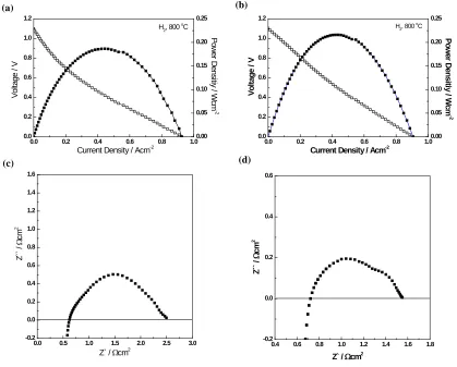
spectra in H2 at 800oC are displayed in Figure 3. In order to further study the electrode
polarization (Rp) during cell performance, the impedance measurement was conducted under open current voltage (O.C.V) condition. The impedance spectra consists of at least
three semicircles and intercept with the real axis: high frequency arc (QHRH), mid
frequency arc (QMRM) and low frequency arc (QLRL) as non-ohmic resistance
(Rp=RH+RM+RL) and ohmic resistance (Rs), suggesting that the high and mid frequency
[image:4.612.156.458.446.505.2]maximum power density with catalyst layer shows 0.22 W/cm2, higher than 0.19 W/cm2
of non-catalyst layered cell at 800 oC. Two or three semicircles were roughly observed on
impedance fitting plot and considering response frequency.
0.0 0.2 0.4 0.6 0.8 1.0 0.0 0.2 0.4 0.6 0.8 1.0 1.2
H2, 800 o C P ow er D ens itiy / W cm -2
Current Density / Acm-2
V ol tage / V 0.00 0.05 0.10 0.15 0.20 0.25
0.0 0.5 1.0 1.5 2.0 2.5 3.0 -0.2 0.0 0.2 0.4 0.6 0.8 1.0 1.2 1.4 1.6
Z` / Wcm2
Z
`` /
W
cm
2
0.4 0.6 0.8 1.0 1.2 1.4 1.6 1.8 -0.2
0.0 0.2 0.4 0.6
Z` / Wcm2
Z
`` /
W
cm
2
0.0 0.2 0.4 0.6 0.8 1.0 0.0 0.2 0.4 0.6 0.8 1.0 1.2
Current Density / Acm-2
V ol ta ge / V 0.00 0.05 0.10 0.15 0.20 0.25 P o w er D en si tiy / W cm -2
H2, 800 oC
(a) (b)
[image:5.612.98.517.100.437.2](c) (d)
Figure 3. I-V curves and impedance spectra in H2 at 800oC for ScSZ electrolyte
supported cells (a,c) without and (b,d) with LCNT catalyst layer.
Clearly the high frequency interception (Rs) has barely changed, though a slight
increase is seen from 0.62 Ωcm2to 0.72 Ωcm2
because of the slightly different thickness of electrolyte support or low conductivity of catalyst layer. Total electrode polarization
reduced from 1.9 Ωcm2 to 0.78 Ωcm2. The high and mid frequencies were reduced
considerably in comparison with Figure 3c and 3d. It indicates that surface activation for hydrogen and charge transfer process improved, but there is no big difference at low frequency because it is not a reforming reaction.
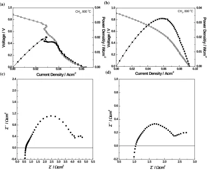
The catalyst layer explicitly affects the stability and performance with methane at
800oC as shown in Figure 4. The O.C.V. and maximum power density of the catalyst
layered SOFC showed a value of 0.915 V and 33 mW/cm2. This is higher than that of
0.882 V and 22 mW/cm2 for the non-catalyst layered SOFC. Although O.C.V. values of
both cells have lower than theoretical value of ≈ 1.1 V due to the insufficient thickness of
anode to fully react with methane and a slower kinetic in comparison with it of hydrogen, it is confirmed that the catalyst layer enhances O.C.V value and stability for methane. Rs
and Rp value of catalyst layered SOFC in CH4 shows 1.04 Ωcm2 and 2.5 Ωcm2, which
pyrolysis of methane (equation 2) is an endothermic dissociation reaction that the C-C bond is weaker than the C-H bond. It is possible to decrease the temperature in some
local areas and lead to increase Rs value, 1.04 Ωcm2 with CH4 from 0.72 Ωcm2 with H2.
In order to further analysis of the anodic polarization, impedance spectroscopy results are undergoing via a three electrode test. Although the thickness of the catalyst layer is not yet optimized for pyrolysis of methane, it demonstrated that the catalyst layer stabilizes SOFC operation in dry methane without carbon deposition.
0.00 0.02 0.04 0.06 0.0 0.2 0.4 0.6 0.8 1.0 V ol ta ge / V
Current Density / Acm-2
0.00 0.01 0.02 0.03 0.04 CH4, 800
o C P o w er D en si tiy / W cm -2
0.0 0.5 1.0 1.5 2.0 2.5 3.0 3.5 4.0 4.5 5.0 5.5 -0.4 0.0 0.4 0.8 1.2 1.6 2.0 2.4 Z `` / W cm 2
Z` / Wcm2
0.5 1.0 1.5 2.0 2.5 3.0 -0.2 0.0 0.2 0.4 0.6 0.8 1.0
Z` / Wcm2
Z
`` /
W
cm
2
0.00 0.02 0.04 0.06 0.08 0.10 0.0 0.2 0.4 0.6 0.8 1.0
CH4, 800 o C
Current Density / Acm-2
[image:6.612.106.513.175.509.2]V ol ta ge / V 0.00 0.01 0.02 0.03 0.04 P o w er D en si tiy / W cm -2 (a) (b) (c) (d)
Figure 4. I-V curves and impedance spectra in CH4 at 800oC for ScSZ electrolyte
supported cells (a,c) without and (b,d) with LCNT catalyst layer.
The catalyst layer was also applied on a Ni-GDC anode supported single cell to
achieve a higher performance at lower temperature, 650oC. The I-V curves and
impedance spectra are displayed in Figure 5. The maximum power density Rs and Rp
values for catalyst-layered SOFC shows over 1.1 W/cm2, and 0.07 and 0.1 Ωcm2,
respectively, which is slightly higher than that of non-catalyst layered SOFC at H2.
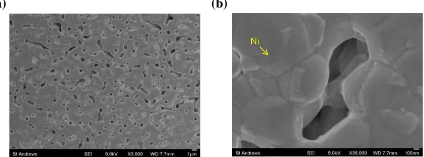
Figure 6 shows the microstructure of LCNT catalyst layer after a cell test in H2 at 650oC.
The firing temperature for forming the layer in fabrication procedure needs to reduce for higher porosity to enable better gas diffusion, as well, the temperature and duration time of reduction require to increase for higher population of the exsoluted Ni particles. The performance of Ni-GDC anode supported single cells with LCNT catalyst
(a) (b)
0.00 0.02 0.04 0.06 0.08 0.10 0.12 0.14 0.16 0.18 0.20 -0.04
-0.02 0.00 0.02 0.04 0.06 0.08 0.10
With a catalyst layer Without a catalyst layer
Z` / Wcm2
Z
`` /
W
cm
2
0.0 0.5 1.0 1.5 2.0 0.0
0.1 0.2 0.3 0.4 0.5 0.6 0.7 0.8
Current Density / Acm-2
V
ol
tage /
V
0.0 0.2 0.4 0.6 0.8 1.0 1.2 With a catalyst layer
Without a catalyst layer
P
ow
er
D
ens
itiy
/
W
cm
-2
H2, 650 o
C
Figure 5. (a) I-V curves and (b) impedance spectra in H2 at 650oC for Ni-GDC anode
supported cells with/without LCNT catalyst layer.
(a) (b)
[image:7.612.109.503.55.215.2]Ni
Figure 6. SEM images of LCNT catalyst layer with (a) x3,000 and (b) x35,000 magnifications.
Conclusions
Non-stoichiometric perovskite (La0.8Ce0.1Ni0.4Ti0.6O3) material for a catalyst layer to direct reforming of methane was successfully prepared. The effects of this layer on electrochemical performance of SOFCs have been investigated. The electrochemical
results from ScSZ electrolyte supported cell using H2 and CH4 as fuel and air as oxidant
showed that LCNT can be successfully utilized as a catalyst layer to prevent the carbon
deposition and reforming of CH4; a maximum power density of ScSZ electrolyte
supported cells with LCNT showed 33 mW/cm2 with 2.5 Ω cm2 of ASR at 800 oC with
operating in CH4. Further, any performance degradation in H2 by the catalyst layer on
Ni-GDC anode supported cell could not be significantly observed.
Acknowledgments
[image:7.612.102.523.262.418.2]References
1. R. Bashyam and P. Zelenay, Nature, 443, 63–66 (2006).
2. E. D. Wachsman and K. T. Lee, Science, 334, 935 –939 (2011).
3. E. D. Wachsman, C. A. Marlowe and K. T. Lee, Energy Environ. Sci., 5,
5498-5509 (2012).
4. R. J. Gorte, H. Kim and J. M. Vohs, J. Power Sources, 106, 10-15 (2002).
5. S. McIntosh and R. J. Gorte, Chem. Rev., 104, 4845-4865(2004).
6. M. J. Taherzadeh and K. Karimi, Int. J. Mol. Sci. 9, 1621–1651 (2008).
7. C. Song, Catal. Today 115, 2–32 (2006).
8. S. Tao and J. T. S. Irvine, Nat. Mater., 2, 320-323 (2003).
9. Y. H. Huang, R. I. Dass, J. C. Denyszyn and J. B. Goodenough, J. Electrochem.
Soc, 153(7), A1266-A1272 (2006).
10.D. Neagu and J. T. S. Irvine, Chem. Mater., 22, 5042–5053 (2010).
11.T. H. Shin, S. Ida and T. Ishihara, J. Am. Chem. Soc., 133, 19399-19407 (2011).
12.J. M. Vohs and R. J. Gorte, Adv. Mater., 21, 943-956 (2009).
13.G. Kim, S. Lee, J. Y. Shin, G. Corre, J. T. S. Irvine, J. M. Vohs and R. J. Gorte,
Electrochem. Solid State Lett., 12(3), B48-B52 (2009).
14.D. Neagu, G. Tsekouras, D. N. Miller, H. Ménard and J. T. S. Irvine,
Nat. Chem., 5, 916–923 (2013)