Original citation:
Mundhenk, Philipp, Mrowca, Artur, Steinhorst, Steinhorst, Lukasiewycz, Martin, Fahmy,
Suhaib A. and Chakraborty, Samarjit. (2016) Open source model and simulator for real-time
performance analysis of automotive network security. ACM Sigbed Review, 13 (3). pp. 8-13.
Permanent WRAP URL:
http://wrap.warwick.ac.uk/80839
Copyright and reuse:
The Warwick Research Archive Portal (WRAP) makes this work by researchers of the
University of Warwick available open access under the following conditions. Copyright ©
and all moral rights to the version of the paper presented here belong to the individual
author(s) and/or other copyright owners. To the extent reasonable and practicable the
material made available in WRAP has been checked for eligibility before being made
available.
Copies of full items can be used for personal research or study, educational, or not-for profit
purposes without prior permission or charge. Provided that the authors, title and full
bibliographic details are credited, a hyperlink and/or URL is given for the original metadata
page and the content is not changed in any way.
Publisher’s statement:
"© ACM, 2016. This is the author's version of the work. It is posted here by permission of
ACM for your personal use. Not for redistribution. The definitive version was published in .
ACM Sigbed Review, 13 (3). pp. 8-13. June 2016
http://doi.acm.org/10.1145/2983185.2983186
"
A note on versions:
The version presented here may differ from the published version or, version of record, if
you wish to cite this item you are advised to consult the publisher’s version. Please see the
‘permanent WRAP url’ above for details on accessing the published version and note that
access may require a subscription.
Open Source Model and Simulator for Real-Time
Performance Analysis of Automotive Network Security
Philipp Mundhenk, Artur Mrowca,
Sebastian Steinhorst,
Martin Lukasiewycz
TUM CREATE, Singapore
<
firstname.lastname
>@tum-create.edu.sg
Suhaib A. Fahmy
School of Engineering, University of Warwick,
Coventry, UK
[email protected]
Samarjit Chakraborty
TU Munich, Germany
[email protected]
ABSTRACT
With the increasing interconnection of vehicles, security challenges have moved into focus. Attacks on in-vehicle networks can cause accidents resulting in financial damages and even loss of life. The im-pact of an attack can be mitigated by secure internal vehicle networks, employing authentication of ECUs and authorization of messages. However, quantifying the real-time performance of additional security measures is difficult due to the high number of nodes and messages. In this paper, we present an open source model and simulator for the evaluation of the real-time performance of automotive networks im-plementing security measures. Applying parameters from hardware measurements, we evaluate our model and simulator with realistic test cases and a case study. We further present application perspectives on how the open source simulator can be used in different domains for the analysis of automotive network architectures.
Categories and Subject Descriptors:C.3 [Special-purpose and application-based systems]: Real-time and embedded systems
General Terms:Algorithms, Design, Security
Keywords:Security, Automotive, Networks
1.
INTRODUCTION
Modern vehicles contain a large number of Electronic Control Units (ECUs), implementing distributed control functions, and in-terconnected over bus systems. Typically, vehicles have between 40 and 100 such ECUs and a variety of heterogeneous bus systems. All electronic functions are realized via this architecture. This includes simple functions, such as the control of lights, as well as more com-plex functions, e.g., Anti-lock Braking System (ABS) and Advanced Driver Assistance Systems (ADASs). ADASs include functions like lane-keeping and, in the future, all sensors and actuators required for autonomous driving.
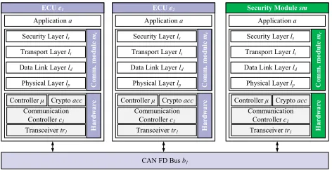
The components of a typical device, e.g., an ECU or security module, are shown in Figure 1. These include hardware compo-nents, such as the central microcontroller, as well as one or multiple communication controllers and transceivers. The microcontroller executes the application software. The communication software is tightly integrated with the hardware of the ECU and shown as the communication module in Figure 1. The communication module can be further subdivided into the layers required for the implemented bus. In a Controller Area Network (CAN) Flexible Datarate (FD) setup, Security, Transport, Data Link, and Physical Layers might be present. In this context, a security layer includes features of session and presentation layers, namely authentication and encryption, while the transport layer contains message segmentation.
In-vehicle networks are increasingly connected to networks out-side the car, e.g., for infotainment purposes or vehicle-to-vehicle
This work was financially supported in part by the Singapore Na-tional Research Foundation under its Campus for Research Excel-lence And Technological Enterprise (CREATE) programme. Copyright retained by the authors
CAN FD Bus b1
ECU e1
Application a
Physical Layer lp
Data Link Layer ld
Transport Layer lt
Security Layer ls
Comm. module
mc
Controller μ Communication
Controller c1
Transceiver tr1 Hardware
Crypto acc
ECU e2
Application a
Physical Layer lp
Data Link Layer ld
Transport Layer lt
Security Layer ls
Comm. module
mc
Communication Controller c1
Transceiver tr1 Hardware
Controller μ Crypto acc
Security Module sm
Application a
Physical Layer lp
Data Link Layer ld
Transport Layer lt
Security Layer ls
Comm. module
mc
Communication Controller c1
Transceiver tr1 Hardware
[image:2.612.317.553.225.346.2]Controller μ Crypto acc
Figure 1:A small subsystem with two ECUs (e1,e2), security module (sm) and CAN FD bus (b1), including internal representation of ECUs and security module. The CAN FD transmission has been extended by a transport layer lt, implementing segmentation according to ISO-TP (ISO 15765-2) and a security layer ls, combining session (authentication) and presentation layer (encryption).
communication. While the interconnection points of internal vehi-cle networks with external networks are often secured with firewalls, these are not impenetrable. When a firewall is bypassed by an attacker, the internal vehicle networks are typically fully accessible. To avoid such situations, a trend towards encryption in internal networks has emerged. To achieve secure encryption, authentication frameworks are required, exchanging symmetric keys. Typically, encryption al-gorithms require significant computational resources, while ECUs in vehicles are often highly specialized, low-performance devices designed to minimize power consumption and cost. Thus, the encryp-tion of messages and authenticaencryp-tion frameworks add a significant latency to communication. This can affect the real-time capabilities of the communication system, potentially leading to catastrophic consequences, including loss of life, if the impact is large enough to hinder efficient control of the vehicle.
However, evaluating the impact of security on real-time behavior is not trivial. It is dependent on a large number of parameters, among them the number of messages to be authenticated, the number of re-ceivers per message, the selected authentication framework, selected encryption algorithms, key lengths for different algorithms, bus data rate, and many others. This impact affects the system in multiple dimensions, as some of these parameters can vary for different ECUs and buses in the network. Further impacts result from the architecture that defines how ECUs are interconnected. The In-Vehicle Network Simulator (IVNS) proposed in this work can assist in the analysis and evaluation of the impact of security measures like authentication and authorization or architecture changes in vehicles.
Contributions. To quantify, analyze, and compare the behavior
automotive networks. Our model and simulator contain a calibration component, allowing the simulation to be adjusted to the performance of selected hardware. This allows easy validation of the simulator and possible extensions through parametrization with existing hardware, as well as comparison with runs on the same hardware. The IVNS is modular and extensible, allowing easy interchange of security protocols and frameworks. The main contributions are as follows.
• We propose a model for automotive networks, containing network components, as well as security frameworks and their parameters (Section 3).
• Based on this model, we develop a discrete event simulator, allow-ing us to analyze and compare security approaches in automotive networks, including, but not limited to authentication frameworks (Section 4). The IVNS is available as open source for free public use under the MIT license [1].
• We evaluate the IVNS for its performance and present a case study of a distributed battery management system. In the case study, we demonstrate how the simulator can support architecture design decisions to ensure real-time behavior of secure automotive networks (Section 5).
2.
RELATED WORK
In the following we introduce the literature related to this work. We give a short overview of general work in automotive security, then discuss some work in security protocols that can be analyzed with the IVNS, before analyzing and comparing existing network simulators.
Automotive Security. In 2010, Koscher et. al. [2] presented a
security analysis of a commercial vehicle, laying the foundation for work in this area. They attacked vehicle networks as a proof-of-concept through wired connections including the On-Board Diagnosis (OBD) port. In the following year, Checkoway et. al. [3] expanded on this research, including remote attacks through the telematics unit of the vehicle under test, as well as the first mention of automotive viruses. In 2015, Miller and Valasek presented a highly effective remote attack on a vehicle via the cellular network [4]. Miller and Valasek attacked an unmodified vehicle and besides taking control over air-conditioning, radio and horn, were also able to influence more safety-critical systems, such as the transmission and brakes.
Approaches to integrate security in vehicle networks have been proposed in [5] and [6], aiming to improve the security of CAN and FlexRay networks, respectively. A highly efficient approach for including authentication of messages was presented in [7]. Message Authentication Codes (MACs) are added to messages and can even be interleaved with the Cyclic Redundancy Check (CRC) for higher efficiency.
However, judging the security and latency of security-enabled networks is difficult. A first approach of a security evaluation for automotive networks was presented in [8]. There, probabilistic model checking is used to analyze the security of a subsystem within a given time frame, based on single component evaluation.
Security Protocols. All protocols used to add security to existing networks are based on an initial root of trust. In the literature, this is typically achieved through a pre-programmed key. However, this key cannot easily be updated and, if not sufficiently secured, might be compromised. Furthermore, identical keys are often used across vehicle models [3], allowing attacks on fleets of vehicles through the analysis of just one. An approach to mitigate such scaling effects in vehicle fleets through CAN message ID obfuscation was presented in [9].
Other approaches use authentication and authorization protocols for key exchange. Timed Efficient Stream Loss-Tolerant Authtication (TESLA) is an authenAuthtication protocol for low-power en-vironments [10]. There, encryption keys are released after use for encryption of a message, allowing authentication of the message sender. However, receiving ECUs are not authenticated and sent messages are not authorized. The Message Authentication Codes (MACs) used do not provide confidentiality. Furthermore, delayed release may add latencies which can be hard to predict.
In [11], the Lightweight Authentication for Secure Automotive Networks (LASAN), a framework specifically tailored to the
auto-motive domain was presented. There, asymmetric and symmetric cryptographic operations are split into authentication and authoriza-tion phases, allowing an efficient setup in automotive architectures.
Network Simulators.In literature, several simulators have been pro-posed for network analysis. The OPNET Modeler [12] is a modular simulation framework that enables protocol and network design for various scenarios, including CAN bus simulations [13]. The tempo-ral behavior of automotive networks, including end-to-end latencies and data throughput, can be analyzed at the bit-level with OPNET. This is ideal for analyzing short sequences of network transmissions with high accuracy. However, longer-term network analysis, such as the setup of a secure communication architecture in a vehicle, is precluded by its performance limits. Thus, in this work, we focus on simulation on the message-level, while taking specified bit timings into account.
NS-2 [14] is a discrete-event simulator that implements numerous network protocols and is able to simulate traffic or routing in networks. It can be extended by user-defined protocol implementations and run various network architectures. Currently, no established support for automotive use cases and protocols exists and such architectures would need to be implemented from scratch, with effort close to that required to design IVNS.
OMNeT++is an open-source discrete event simulation frame-work that provides tools to write and run simulations for any type of network [15]. It enables large-scale simulations, visualization of message flows, and can be extended with user-defined protocols and architectures. Internal automotive networks such as CAN or Ethernet can be analyzed and implemented by this framework [16]. However, implementing our proposed model into the rigid framework of OM-NeT++, especially including the parametrization of the components, is cumbersome. Database lookups, as well as filtering, formatting, and exporting of results create additional hurdles. Thus, implemen-tation in OMNeT++would exceed the effort of implementing the model in a new environment. Once our model and approach are implemented, these can be combined into an OMNeT++library in future work.
Other commercially available simulators are Timing Architects’ Simulator [17], Symta Vision’s SymTA/S & Trace Analyzer [18], and Inchron’s ChronSIM [19]. While [17] is focused exclusively on the simulation of multi-core systems, [18] and [19] also support the simulation of networks. However, while these tools offer many interfaces for integration with existing workflows in the automotive industry, the libraries for simulating components and protocols are limited to those supplied by the manufacturer, and cannot easily be extended to enable prototyping of security measures. Neither offers security protocols.
3.
MODEL
In this section, we define the simulation model formally. The model is required to represent a security-enabled automotive archi-tecture, as well as the configuration and calibration of the simulation. While the architectureAunder test is the target of any analysis, the configurationCdefines the basic configuration of the system and simulator, such as the used cryptographic algorithms and validity pa-rameters. The calibration, in turn, is based on benchmarksPcreated on real-world systems, thus tuning the components of the architecture to represent existing hardware. Furthermore, the model can be vali-dated through comparison with real-world systems, based on the set of parameters used for calibration and obtained from the same hard-ware. We follow a compositional approach, combining these basic simulation components to represent the complete system behavior.
The IVNS defines a simulationswhich contains the architecture
Ato be evaluated, the configurationC, as well as a set of parameters
P, depicted in Figure 3:
s=(A,C,P) (1)
Architecture.The architectureAcontains the set of ECUsE, buses
B, and gatewaysG, as well as their interconnectionsI:
A small subsystem is shown in Figure 1.
An ECUe∈Eis identified by its applicationa, one or multiple communication modulesmc∈MCand its hardware implementation
HW:
e=(a,MC,HW) (3)
The hardware components HW define the latencies tinduced in every communication modulemc. These components are the central processorµ, one or multiple communication controllerso∈O, as well as one or multiple transceiverstr∈T generating the physical signals. Furthermore, an ECU might contain a hardware accelerator
accfor cryptographic operations:
HW=(µ,O,T,acc) (4)
Each applicationarunning on an ECUesends a set of messages
m∈M. All messages with the same message identifieridare called a streamMid. Each messagemin such a streamMidis called a
mes-sage instance, or mesmes-sage. A mesmes-sage instancemcan be secured by a functionsec(m). A stream needs to be authorized by a function
auz(Mid). Depending on the security settings of the simulation,
func-tionauz(Mid) may trigger a set of authentication and/or authorization
functions. In LASAN, e.g., an authenticationauc(e) is performed per ECU, after which message streams may be authorized.
The number of communication modulesmc∈MCdepends on the number of controllers and transceivers available and used by the ECU. A communication modulemcmay contain all or a subset of layers as defined in the Open Systems Interconnect (OSI) model. This includes an application layerla, a presentation layerlpr, a session layerlse, a
transport layerlt, a network layerln, a data link layerldand a physical
layerlp:
mc=(la,lpr,lse,lt,ln,ld,lp) (5)
Many bus systems require only a subset of these or summarize cross-layer functions. In CAN FD with segmentation according to ISO 15765-2, e.g., only transport layerlt, data link layerld, and
physical layerlpare used. Furthermore, cross-layer security functions
of session and presentation layer can be summarized as a security layerls. Cryptographic operations such as encryption/decryption and
signing/verification are located in this security layerls. The security
layer further handles stream initiation and authentication frameworks such as LASAN and TESLA.
Some authentication frameworks, such as LASAN, require a root of trust in the network. Being an ECU with defined security functions, a security modulesm∈Eis defined as an ECU. The same holds for a gatewaygw∈G, which is a type of ECU (G⊂E) with multiple interfaces where the application layer is filtering and forwarding messages depending on an Access Control List (ACL):
sm=gw=(a,MC,HW) (6)
A busb∈ Bis defined by its properties, including data rated, maximum message lengthlmax, bus access schememac, and the
velocity factorυPof the medium:
b=(d,lmax,mac, υP) (7)
Configuration. The configurationCcontains the settingscvalid for all components. This configuration defines the framework of the simulation, including the parameters such as key lengths and selected algorithm for encryption/decryption, signing/verification and hashing algorithms on ECUs, as well as other settings, such as the validity of nonces and certificates and maximum simulation times. The settings are dependent on the implemented layers and protocols, which can define and load any configuration setting and can thus be extended easily.
C=(algsym,keylensym,algasym,keylenasym,alghash) (8)
Other possible settings could be different operating modes for the security frameworks, caches or components, such as gateways.
CAN FD Bus b1
ts(a)
ts(lt)
ts(ld)
ts(lp)
tb
tr(lp)
tr(ld)
tr(lt)
tr(a)
Message Transmission Latencies ECU e1
Application a
Physical Layer lp
Data Link Layer ld
Transport Layer lt
Security Layer ls
Comm. module
mc
ECU e2
Application a
Physical Layer lp
Data Link Layer ld
Transport Layer lt
Security Layer ls
Comm
. module
mc
[image:4.612.317.552.61.161.2]ts(ls) + tauz tr(ls)
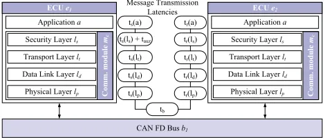
Figure 2:Components of message transmission latencies per layer, as defined in our model. Function tsdefines the sending time, function trdefines the receiving time, per layer, respectively. Depending on the security setup of the system, the security layer has high and varying influence on the message trans-mission latency, being responsible for encryption, as well as authentication and authorization.
Parameters.The parametersp∈Pare used to calibrate the IVNS to a real-world environment. Calibration parameters are typically ob-tained by benchmarking existing hardware. The calibration is crucial to be able to simulate reality as accurately as possible. Furthermore, this allows validation of the model and simulator through compar-ison of a calibrated simulation with the underlying hardware used for calibration. The required measurements depend on the selected algorithms but typically include cryptographic parameters, such as encryption/decryption, signing/verification, hashing, key generation, as well as transmission related parameters, such as gateway latencies and bit transmission times for the selected buses.
P=(tenc,tdec,tsign,tverif,thash,tGW,ttx) (9)
Parameters can be defined as constants (e.g., bit timing on bus), lookup tables (e.g., encryption/decryption latencies) or functions (e.g., hashing latency). The parameters are loaded at runtime, based on the configuration of the individual components depending on these parameters. Furthermore, they are applied per ECU and can thus be used to define varying hardware for ECUs of different computational capabilities.
Message Flow. The components described above determine the
latencies a message experiences when being sent. Every component and every layer defines and adds its own latencies. A simple message transmission is shown in Figure 2.
A message thus experiences the following delaytmin conventional
transmission, wherets,tbandtrare sending, bus and receiving delays,
respectively:
tm=ts+tb+tr (10)
These components can be defined in more detail based on the layers (see Figure 2). On the sending ECU, a message experiences a delayts, which consists of the sending delays of the applicationts(a),
the security layerts(ls), the transport layerts(lt), the data link layer ts(ld) and the physical layerts(lp):
ts=ts(a)+ts(ls)+ts(lt)+ts(ld)+ts(lp) (11)
The bus introduces latencytb, mostly depending on the data rate
of the bus and the size of the message, as well as the velocity factor. On the receiving ECU, the message experiences a further latencytr,
consisting of the receiving latencies of the physical layertr(lp), the
data link layertr(ld), the transport layertr(lt), the security layertr(ls)
and the applicationtr(a):
tr=tr(lp)+tr(ld)+tr(lt)+tr(ls)+tr(a) (12)
In case an authentication protocol is used, the first message might experience a longer sending delayta, as first, the authentication and
authorization need to be performed. In this case
ta=tauz+ts+tb+tr, (13)
wheretauzis highly dependent on the authentication and authorization
size of messages required, as well as the selected authentication mechanisms and their speed on the ECU.
Protocols. The above latencies are the abstraction level of events for a discrete event simulation on the basis of OSI layers. The latencies per layerlare required to be calculated at runtime, based on the chosen implementation (e.g., CAN FD), required algorithms (e.g., encryption), state of the system (e.g., bus load) and inputs (e.g., message length), among others. Thus, the implementation needs to take into account the behavior of the layerlas defined in its specification, as well as the measurements of basic hardware parameters, as defined in the parametersP. The accuracy of the abstraction is defined through the detail of implementation. The runtime values might vary considerably, based on, e.g., bus access for
tbor, in case of LASAN, a potential authentication required before
authorization, triggering a separate set of message transmissions. To achieve higher performance, these sub-layer latencies are computed at runtime and abstracted to a single event in the model, reducing the number of events considerably and thus increasing computational performance.
Modularity. The complexity of the model pays offwhen attempt-ing to compare different networks. All components have defined functions, settings and interfaces. This allows a high amount of modularity in the system, as every component can be exchanged as required. For example, to exchange a bus system, only the imple-mentation of the busbneeds to be adjusted. In the same manner, the authentication and authorization framework can be exchanged by changing the security layerls. Furthermore, the underlying hardware
for an ECUeor the security modulesmcan be easily exchanged, sim-ply by switching the parameter setP. In this way, it is easily possible to, e.g., add a cryptographic accelerator to an existing architecture.
Alternatively, single ECUs may be configured with a different set of parameters, only applicable to a specific ECU. This allows creation of different ECUs, some more powerful than others. While the base ECU of the architecture could be an 8-bit controller, e.g., used for the outer mirror of a car, some ECUs, such as the infotainment unit, might be significantly more powerful.
Granularity.This model represents the basic setup of an automotive architecture, including security components. The key to performance in the development of a simulation model is the abstraction level. Too detailed a model may result in unreasonably long computation times, while too highly abstracted a model results in insufficient accuracy of results.
We chose the abstraction level of our model to be especially effi -cient for the analysis of long-term processes in automotive systems, such as protocol analysis. To achieve this, we do not model single bit times as separate events, but summarize a set of latencies calculated at runtime into a single event in our discrete event simulation. The chosen abstraction for our model is on the level of OSI layers. We separately model the layers as events, but base the timeouts on the pa-rameter setP. This allows us to calculate latencies in the system with the accuracy of the smallest measurable time component, typically 1 bit time on the bus. However, due to bit times being summarized in events per layer, these smallest latencies cannot be exported or analyzed individually. Therefore, The smallest level for analysis is an OSI layer latency.
4.
SIMULATION
The simulation framework implements the model as described in Section 3. The Python language has been used for implemen-tation. Using an interpreted language like Python allows fast and easy extension of components. Furthermore, a large number of li-braries are available, speeding up the implementation process, and simplifying future extension by the community. The discrete event handling is based on the Python library SimPy [20]. An overview of the components of the IVNS is given in Figure 3.
The simulation environment is set up with the given configuration
C, typically read from configuration files. The network architectureA
is either defined by the user, or generated by a test case generator and fed into the core of the simulation environment. The test case
gen-Parameters P
export
status export
results tune
Configuration C
GUI CSV file
export
Database
Config. files
Hardware Parameters
Test case generator
Architecture A
configure model
Core
API
sm
e1
e2
e3 e5
e6
e4 e7
e8
e9 e11
[image:5.612.318.551.58.146.2]e12 e10 gw
Figure 3:Architecture of the simulator with a 12 cell setup on a single bus. The IVNS includes a test case generator generating architecture A, database of hardware parameters P, configuration files C, as well as GUI and CSV output via an API.
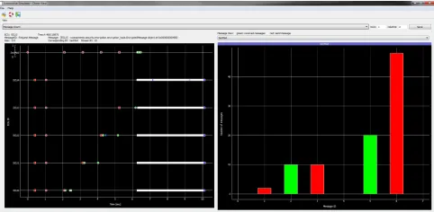
Figure 4: A screenshot of the GUI. Here, a LASAN setup is shown. The Event View (left) shows every message sent and received on all buses. Red markers indicate the authentication of ECUs, green markers indicate the authorization of streams, and blue markers indicate data messages, occurring with significantly higher frequency after all streams have been set up securely. The Message View (right) shows the number of messages sent (red) or received (green) by a device, in this case the Security Module.
erator uses statistical processes to generate new architectures, based on a set of parameters for the architecture. These parameters include the number of ECUs, number of messages, etc. This architecture is calibrated by the parametersP, taken from hardware benchmarks. In our case, these benchmarks have been performed on an STM32F415 microcontroller for software and hardware implementations of cryp-tographic functions. These benchmarks will be published together with the IVNS for free use.
The Graphical User Interface (GUI) supports different plugins for analysis of the running system. A screenshot of the Event View and Message View is shown in Figure 4. There, the setup and operation of a system with the LASAN authentication framework, 5 ECUs and one security module are shown.
Every component in this simulation is built in a modular fashion and is easily exchangeable. A reporting and filtering system is in place, allowing collection, display, and export of any value in any of the components. These values could include the state of the ECU and security module buffers, the load on the bus, or the internal state of any task on an ECU. Reported values can be filtered to maximize performance of the IVNS and minimize the storage required for export files.
The IVNS has been built from the ground up with parametrization in mind. This allows easy import of externally generated parameters, e.g., latencies for encryption/decryption operations or the forwarding latency in a gateway, making the IVNS highly flexible. Initially, all implemented ECUs are based on an STM32 controller, but by adding parameters P measured on other devices, the IVNS can flexibly simulate any automotive networking environment.
5.
EXPERIMENTAL RESULTS
[image:5.612.314.555.195.313.2]20 40 60 80 100 0
200 400 600
Number of ECUs
Computation
T
ime
/
s
100 150 200
A
v
erage
Memory
Usage
/
MB
[image:6.612.56.294.52.164.2]LASAN time TESLA time LASAN memory TESLA memory
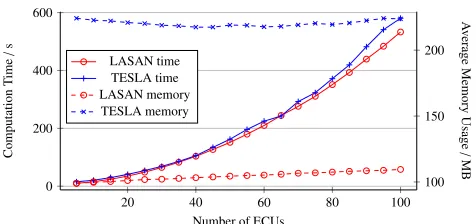
Figure 5:Evaluation of computation time and average memory consumption of the simulator for architectures of different size and different authentication frameworks. IVNS stays below 10 minutes of computation time and below 250 MB of RAM for any realistic test case.
of a distributed battery management system how IVNS can be used to feed back performance data to the architecture design process. All computations in this section have been executed on an Intel Core i5-3450 CPU with 4 GB of RAM.
5.1
Synthetic Test Cases
To evaluate the computational and memory performance of IVNS, we implement two authentication protocols, LASAN and TESLA. Using the built-in test case generator (see Figure 3), we automatically generate architectures of varying sizes. These architectures include a varying number of ECUs and 500 messages. The number of receivers per message increases with the number of ECUs. This demonstrates the multicast behavior of messages in automotive networks.
The results are shown in Figure 5. As it can be clearly seen, the average memory requirement for a TESLA simulation stays fairly constant below 250 MB, even for large systems with up to 100 ECUs. The average memory usage for a LASAN simulation increases linearly, resulting from the larger number of messages transmitted in the system and needing to be stored in buffers. However, even for 100 ECUs, the memory requirement is less than half that of a TESLA simulation. As the number of receivers increases, the number of message objects to be processed in the separate receiving ECUs also increases. The higher memory requirement of the TESLA simulation originates from the number of keys being stored for all messages in the system. Here, we generate a chain of 400,000 keys, which is stored on the ECUs and applied in reverse order. This number is reasonable, as for a message with a period of 10 milliseconds, this set of keys lasts about 1 hour. In any case, the memory consumption for simulation of systems of realistic size stays below 250 MB, which is very low for modern desktop computers.
When evaluating the computation time required to simulate a net-work, we see a clear correlation between LASAN and TESLA in our simulator. This is expected, as both systems follow the same ECU-and bus-internal message sending sequences, as defined in Section 3. Though the computation time exhibits exponential behavior, even for large systems, it remains below 10 minutes. As in the automotive domain systems rarely exceed the threshold of 100 participants on the bus, this computation time is reasonable.
As all computations have been performed on a commercial off -the-shelf desktop computer, IVNS is ideal for evaluating automotive networks in a design environment. There, the feedback of the simu-lator can be used as an input to the optimization functions of other tools, or, as will be shown in the following case study, as feedback to the designer.
In summary, IVNS can be used to efficiently analyze automotive architectures of different sizes on commercial desktop computers, en-abling designers to ensure real-time requirements while prototyping secure applications and security protocols. In the case of LASAN vs. TESLA, e.g., our simulator shows that LASAN allows setup of streams significantly more efficiently than TESLA, with stream setup times faster than 2 ms, on ECUs with cryptographic hardware accelerators.
5.2
Case Study
To show the applicability of IVNS to real-world applications, we analyze the case study of a distributed embedded Battery Manage-ment System (BMS), as might be used in next-generation Electric Vehicle (EV) batteries [21]. In this system, each cell in a battery is equipped with a microcontroller, allowing it to survey its own State of Charge (SOC) and State of Health (SOH). Furthermore, such a setup can allow battery cells to exchange charge and thus implements active cell balancing in a distributed fashion. Secure communication is of particular importance in the context of such BMSs to ensure the safety of high-energy Lithium-Ion (Li-Ion) cells.
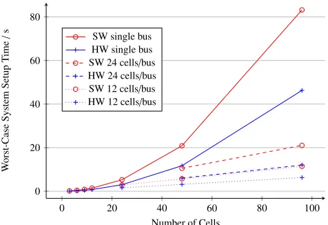
In the following, we analyze the distributed battery management with and without cryptographic hardware acceleration, as well as for different numbers of cells and network topologies. The system is secured with the authentication framework LASAN. Different numbers of cells are used in different applications. Starting from 3 battery cells, such as for laptops, we increase the architecture size to 24 and 48 cells, often in use for electric bicycles and hybrid electric vehicles, respectively, up to 96 cells, such as in use for EVs. The architecture choice we investigate is the division of cells onto buses and has a large influence on complexity, weight and cost of the system. The number of buses, and a gateway, if required, cause additional weight and cost. On the other hand, connecting all battery cells to a single bus can lead to an increased bus load and thus system setup time, as all cells have to negotiate secure messages. The results are shown in Figure 6, illustrating the worst-case system setup time, representing authentication and authorization over the number of battery cells in the system. To estimate the worst-case setup time of the system, we assume that all battery cells need to transmit all status messages and charge exchange requests at the same time, right at the start of the system. While this is not a realistic test case (typically such transmissions are spread over a range of hours), it gives us a worst-case estimate for the setup time.
Evaluation. From Figure 6, we see that the hardware-accelerated system is significantly faster than the software-only implementations in all cases. This behavior is expected. The system setup time exhibits an exponential behavior, increasing with the number of cells in the system. This is due to the fact that the employed distributed battery management system uses broadcasts on nearly all messages. To achieve full security across all these messages and nodes, LASAN needs to exchange grant messages and cryptographic keys with every receiving ECU for every message to be sent.
In the case of large systems on a single bus, such as batteries for electric vehicles with 96 cells, hardware accelerated, as well as software only implementations, exhibit a very high latency of about 50 to 80 seconds.
Based on the behavior of LASAN and the requirements of the system, a designer might want to split the system into multiple buses. While this should decrease the setup time, quantifying the latency advantage is not trivial, due to it being based on the number of mes-sages in the system and the number of receivers per message, as well as the performance of all ECUs. With IVNS, the system can easily be split into buses of different sizes. Results of these tests are also shown in Figure 6 for 12 and 24 cells per bus and hardware accelerated, as well as software-only implementations, respectively. As this split onto multiple buses leads to a large amount of parallelization across buses, the worst-case system setup time can be reduced significantly. In case of an electric vehicle battery with 96 cells and 12 cells per bus, the system setup time can be reduced to below 10 seconds. As for other systems the exponential behavior does not have such a large influence, the savings are smaller, yet significant. In the case of 48 cells, a typical hybrid electric vehicle battery, e.g., the setup time can be reduced from over 20 seconds to about 3 seconds, when using 12 cells per bus.
0 20 40 60 80 100 0
20 40 60 80
Number of Cells
W
orst-Case
System
Setup
T
ime
/
s
[image:7.612.57.295.52.215.2]SW single bus HW single bus SW 24 cells/bus HW 24 cells/bus SW 12 cells/bus HW 12 cells/bus
Figure 6:Case study of a distributed embedded battery management system with the LASAN authentication framework. The worst-case system setup time has been analyzed for different systems with (HW) and without (SW) cryptographic hardware accelerators. Furthermore, the impact of the module size, or cells per bus on the setup time, is evaluated.
hardware acceleration. For the designer of an electric bike with 24 cells and similar requirements, the simulator clearly shows that the additional cabling effort and cost for hardware accelerated controllers required for a splitting of buses does not lead to much shorter setup times. In this context, the IVNS can be integrated with the design for secure communication architectures in vehicles.
6.
APPLICATION PERSPECTIVES
With the open source release of IVNS, we enable the scientific community to address open challenges in the area of automotive networks. The IVNS can be used to analyze a multitude of parameters in different vehicle networks, setups, protocols, etc. Thanks to its flexible model, it can be used in any research environment related to automotive networks where reality-backed evaluations are performed. The following list offers a base set of scenarios where the IVNS can be applied:
• To develop new protocols and analyze these protocols for their performance in varying automotive scenarios.
• To evaluate different architectures including feedback for Design Space Explorations (DSEs) and optimization problems in a multi-tude of configurations.
• Modularity and clearly defined Application Programming Inter-face (API), as well as the interoperability of the underlying Python, mean extending the simulator to evaluate software components in a Software-in-the-loop (SIL) simulation is easy, e.g., for newly developed control algorithms.
• Similar to SIL simulations, Hardware-in-the-loop (HIL) tests can be executed where existing hardware (sub-)systems are mixed with software simulations, e.g., for restbus simulations.
• The high performance of the simulator allows to simulate virtual prototypes of (sub-)systems to vehicle level size architectures.
• When integrated with other evaluation mechanisms, IVNS can be used to allow multi-objective evaluations of automotive systems, e.g., for security and real-time performance.
• Modularity allows the inclusion of further bus systems and layers, thus enabling simulation of communication systems and layers not yet defined. The different possible implementations of Automotive Ethernet could, e.g., easily be compared.
• Integrating the highly flexible IVNS with existing simulators, such as OMNeT++, e.g., in the form of a library, to combine the power of both approaches into a multi-functional automotive simulator. The modularity, as well as the option to calibrate the simulator with real hardware measurements, allows many possibilities for the use in the research community. The approaches listed above are an introduc-tion to the domain of quantifying behavior in vehicle architectures, but are by no means exhaustive. The open source and free nature of
the selected MIT license allows adjustments of the simulator of any kind. Feedback from community development is appreciated and can be integrated easily through established contribution mechanisms.
7.
CONCLUSION
In this work, we have presented an open source framework for modeling and simulating secure automotive networks, allowing real-time performance analysis. The model includes components and interconnections in automotive networks, a basic configuration, as well as a set of parameters. Parameters can be supplied to tune the components to real-world behavior. The simulator is implemented in Python and is highly modular, allowing easy extensibility. It is available as open source for free use by the research community and industry. By modeling a sufficiently high abstraction level of events, we achieve high performance in terms of computation time and memory requirements, analyzing networks of up to 100 nodes in under 10 minutes, while keeping memory utilization below 300 MBytes. The usefulness of the simulator has been presented in a case study to quantify the real-time behavior of a secure distributed battery management system. By adjusting the architecture slightly, the performance of the system could be increased by close to an order of magnitude.
8.
REFERENCES
[1] P. Mundhenk, A. Mrowca, S. Steinhorst, M. Lukasiewycz, S. A. Fahmy, and S. Chakraborty. Online repository for simulator software.
https://github.com/PhilippMundhenk/IVNS, 2015.
[2] K. Koscher, A. Czeskis, F. Roesner, S. Patel, T. Kohno, S. Checkoway, D. McCoy, B. Kantor, D. Anderson, H. Shacham, and S. Savage. Experimental
Security Analysis of a Modern Automobile. InProc. of SP, 2010.
[3] S. Checkoway, D. McCoy, B. Kantor, D. Anderson, H. Shacham, S. Savage, K. Koscher, A. Czeskis, F. Roesner, and T. Kohno. Comprehensive experimental
analyses of automotive attack surfaces. InProc. of USENIX, 2011.
[4] C. Miller and C. Valasek. Remote Exploitation of an Unaltered Passenger
Vehicle. InProc. of Blackhat, 2015.
[5] C.-W. Lin, Q. Zhu, C. Phung, and A. Sangiovanni-Vincentelli. Security-aware
mapping for CAN-based real-time distributed automotive systems. InProc. of
ICCAD, 2013.
[6] G. Han, H. Zeng, Y. Li, and W. Dou. SAFE: Security-aware flexray scheduling
engine. InProc. of DATE, 2014.
[7] R. Zalman and A. Mayer. A Secure but Still Safe and Low Cost Automotive
Communication Technique. InProc. of DAC, 2014.
[8] P. Mundhenk, S. Steinhorst, M. Lukasiewycz, S. A. Fahmy, and S. Chakraborty. Security Analysis of Automotive Architectures using Probabilistic Model
Checking. InProc. of DAC, 2015.
[9] M. Lukasiewycz, P. Mundhenk, and S. Steinhorst. Security-aware Obfuscated
Priority Assignment for Automotive CAN Platforms.ACM TODAES, 2015.
[10] A. Perrig, D. Song, R. Canetti, J. D. Tygar, and B. Briscoe.Timed Efficient
Stream Loss-Tolerant Authentication (TESLA): Multicast Source Authentication Transform Introduction. Number 4082 in Request for Comments. IETF, 2005. [11] P. Mundhenk, S. Steinhorst, M. Lukasiewycz, S. A. Fahmy, and S. Chakraborty.
Lightweight Authentication for Secure Automotive Networks. InProc. of DATE,
2015.
[12] Riverbed Technology. Riverbed modeler.http://www.riverbed.com/
products/steelcentral/steelcentral-riverbed-modeler.html,
downloaded October 12th 2015.
[13] J. Hao, J. Wu, and C. Guo. Modeling and simulation of CAN network based on
OPNET.Proc. of ICCSN, 2011.
[14] T. Issariyakul and E. Hossain.Introduction to Network Simulator NS2. Springer
Publishing Company, Incorporated, 2008.
[15] A. Varga and R. Hornig. An Overview of the OMNeT++Simulation
Environment. InProc. of Simutools. ICST (Institute for Computer Sciences,
Social-Informatics and Telecommunications Engineering), 2008.
[16] J. Matsumura, Y. Matsubara, H. Takada, M. Oi, M. Toyoshima, and A. Iwai. A
Simulation Environment based on OMNeT++for Automotive CAN–Ethernet
Networks. InProc. of WATERS, 2013.
[17] Timing-Architects Embedded Systems GmbH. Simulator.
http://www.timing-architects.com/ta-tool-suite/simulator, 2015.
Accessed: 2015-11-23.
[18] Symtavision GmbH. SymTA/S & Trace Analyzer.
https://www.symtavision.com/products/symtas-traceanalyzer,
2015. Accessed: 2015-11-23. [19] INCHRON GmbH. chronSIM.
http://www.inchron.com/tool-suite/chronsim.html, 2015. Accessed:
2015-11-23.
[20] Team SimPy. SimPy Discrete Event Simulation Library for Python.
http://simpy.readthedocs.org, 2015. Accessed: 2015-11-23.
[21] S. Steinhorst, M. Lukasiewycz, S. Narayanaswamy, M. Kauer, and
S. Chakraborty. Smart Cells for Embedded Battery Management . InProc. of