Automatic Generation of Human Machine Interface Screens from Component-Based
Reconfigurable Virtual Manufacturing Cell
B.Ahmad, X.Kong, R.Harrison WMG, University of Warwick
Coventry, United Kingdom
{b.ahmad, xiangjun.kong, robert.harrison}@warwick.ac.uk
J.Watermann, A.W.Colombo* *University of Emden, Germany
*Schneider Electric, Germany [email protected]
Abstract— Increasing complexity and decreasing time-to-market require changes in the traditional way of building automation systems. The paper describes a novel approach to automatically generate the Human Machine Interface (HMI) screens for component-based manufacturing cells based on their corresponding virtual models. Manufacturing cells are first prototyped and commissioned within a virtual engineering environment to validate and optimise the control behaviour. A framework for reusing the embedded control information in the virtual models to automatically generate the HMI screens is proposed. Finally, for proof of concept, the proposed solution is implemented and tested on a test rig.
Keywords— virtual engineering, component-based automation, human machine interface, programmable logic controllers, control systems
I. INTRODUCTION
In recent years, the automotive industry has been significantly affected by a number of challenges driven by the globalisation, economic fluctuation, environmental awareness and rapid technological developments. As a consequence, the product lifecycles are shortening and the customer demands are becoming more diverse. This drives automotive manufacturers to introduce new innovative cars into the market frequently with as many extras as possible. To survive in such a business environment, manufacturers have to find a cost effective solution for fast and efficient adaption of their resources to satisfy the needs of changing markets and customer demands without losses in production [1-3].
Production lines in the automotive industry are highly automated and heavily rely on control systems. The conventional engineering approach to build automotive production systems, which consists of mechanical, electrical and control engineering, in the exact sequence, occurs independently and integrates only at the final stage during commissioning. This often results in finding inconsistencies only at a very final stage and leads to a prolonged ramp-up time [4]. Not only this sequential engineering method, but also the use of department specific tools and insufficient ways of information handling further worsen the ramp-up time. As industries are trying to increase the responsiveness, the weaknesses of using department specific tools are becoming
more obvious. These include repeated work, loss of information, use of different data structures, and lack of integration between the engineering disciplines [5].
To save time during the development, so-called Virtual Commissioning (VC) is now used more frequently within the automotive industry. Virtual Commissioning refers to modelling and simulating the production machine in a 3D simulation environment [6, 7]. This allows control engineers to start programming the control system at an early stage of the machine development. These programs can then be tested against the 3D simulation model to verify the control behaviour before the physical build. However, programming is still manual, which leads to error-prone code due to human mistakes [8].
To avoid manual programming, a new approach is to generate the control software automatically from the 3D virtual models of the machines. Virtual machine models used for virtual commissioning have embedded control behaviour; therefore, the same data can potentially be reused and converted into the desired control code [9]. The goal of such an approach is to make the programming of the control systems intuitive as the control behaviour can be defined at a higher level of abstraction in 3D virtual engineering tools removing the need for complicated low-level programming [10].
The focus of this paper is the development of a self-configurable HMI based on the reuse of information from component-based 3D virtual models of manufacturing cells. The HMI typically consists of a number of screens to provide a graphical user interface to the operator to control and monitor a manufacturing system. The generated screens are essentially template-based, wherein the template is populated from machine specific configuration data imported from the virtual model of a manufacturing cell.
II. BACKGROUND
A. State-of-the-art Engineering Practice within Automotive Industry
builders and control vendors [11]. End-users are the automotive production companies. Machine builders, also known as Original Equipment Manufacturers (OEMs), are the Tier-1 suppliers to the end-users. They are responsible for the design and build of manufacturing systems. Control vendors are the Tier-2 suppliers and provide control hardware to the end-user [12]. Collectively all these partners are responsible for the implementation and lifecycle support of the manufacturing systems.
Typically, as witnessed in the automotive industry, the existing approach of developing automation systems follows a classical sequential engineering workflow. The development stage starts with the overall production-line layout, which is derived from the manufacturing process requirement, followed by the mechanical design, electrical design, and lastly the implementation of the control software for the individual workstations. All these activities are carried out in a rigid sequential order with very little concurrency. Once a machine is assembled and integrated, the final stage is then the commissioning [4, 5]. Each engineering discipline has very individual requirements. For this reason, at each stage customised and dedicated engineering tools are used, which leads to heterogeneous tools landscape and different data structures [13, 14]. As a consequence, the engineering activities remain isolated and the integration is only carried out with ad-hoc methods.
Writing control logic and developing the accompanying operator interface is one of the most time-consuming and complex portions of the machine build process. The control programs for the PLC and the HMI are typically implemented in vendor specific engineering tools using a set of vendor specific and IEC languages. In order to have consistency and a common look, the end-user creates a template of the structure of the PLC program and design of HMI screens that must be complied with by all of its machine builders. With this approach, though reuse of some part of the program code is possible but it is done via cut and paste method. However, this is a very ad-hoc form of program reusability. It is difficult to reuse programs widely with confidence and is open to human errors. Furthermore, there is a little or no support for version control and direct-integration between PLC and HMI. These characteristics make changeability and future reuse of the automation projects very difficult, error prone and expensive. This eventually results in a prolonged commissioning, ramp-up and maintenance times [15].
In addition, there is no industrially established way to verify the control behaviour of machines at the time of writing control logic. As the physical machine and the control system design activities remain isolated, therefore, final verification and validation of the control logic cannot be carried out until the commissioning phase. This typically leads to the need for changes in the control logic during commissioning, ramp-up and production phase of a manufacturing system.
B. Virtual Engineering Approach
The recent trend in the manufacturing engineering domain is the use of IT tools to support the verification and validation of manufacturing systems in a 3D virtual environment, often referred as virtual commissioning. Virtual commissioning tools typically provide a digital collaborative engineering environment in which mechanical design, process engineering and control engineering can be integrated into a 3D dynamic model of a manufacturing system [16]. The use of such engineering tools makes the development process no longer isolated activities and enables valuable collaboration across engineering disciplines during the machine development. Especially, it allows control engineers to work closely with mechanical and process engineers to optimise the control behaviour at an early stage [6].
Virtual commissioning allows the user to carry out commissioning activities without having real production facilities [17], thus providing a platform to improve the performance of manufacturing systems even before it is physically build. Once a machine is virtually built, the verification of a system can be carried out via visual inspection of a 3D CAD model of a machine [18]. A number of designs, configurations, and “what-if?” scenarios can be easily simulated that are otherwise difficult and time consuming if performed on the shop-floor. This essentially creates a new parallel process and removes much of time pressure that exists in the classical sequential approach [6]. Hence, significant reduction in the ramp-up time can be achieved by identifying structural defects and verifying the control behaviour in the early stage of a machine build process [19, 20].
In academia, virtual commissioning has been acknowledged for more than a decade for identification of the design flaws and inter-domain problems. Industry has also recognised the potential significance of the virtual engineering. Particularly, in the automotive sector virtual commissioning is becoming more common in a number of production areas, such as body-in-white and engine assembly. One of the main hindrances of its wider acceptance in the industry is the additional effort needed for creating the simulation models. However, the use of pre-defined standard library components can significantly reduce the model development time.
III. A NEW INTEGRATED ENGINEERING APPROACH FOR
AUTOMATION SYSTEM DEPLOYMENT
An Integrated Engineering Tool (IET), has been developed to support the virtual construction of automation systems for process validation, control behaviour definition, commissioning, and direct deployment of runtime control systems. This IET provides a number of functions to create 3D machine components with embedded kinematic behaviour, control logic and diagnostics. These components are then assembled to build a required system. In this system, virtual operator (known as V-Man) can also be simulated for the cycle time calculation and generation of MODAPTS (MODular Arrangement of Predetermined Time Standards) sheet.
[image:3.595.306.559.246.372.2]The IET is based on the component-based approach, proposed by Harrison et al. [21], that decompose production machines into independent and reusable components to build and reconfigure production machines. The research objective is to develop a practical and effective engineering tool to provide a collaborative engineering environment that allows construction of reusable machine components (consisting of automation hardware and software) that could be easily integrated, reconfigured and deployed to produce a desired automation system. This engineering approach can potentially offer a significant reduction in the machine development and reconfiguration time over the conventional engineering approach.
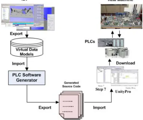
Fig. 1. Automatic Control Software Generation Framework
The framework for control software generation using the IET is shown in Fig. 1. After virtual simulation and validation of a manufacturing cell, the cell information is exported in XML-based open data format to the PLC runtime installation module. The runtime installation module, known as Mapper, provides user interface for the configuration of the control logic to define the I/O mapping of the physical addresses and the mapping of resource specific standard function blocks with the actuators and sensors of the manufacturing cell. Once all actuators and sensors are configured, the Mapper processes the
information to generate Control Data Model. The Control Data Model is then automatically integrated with the end-user specific PLC program template to generate a deployable PLC code. The detailed discussion of the generation of PLC code is beyond the scope of this paper. However, some discussion of the approach can be found in [8, 20].
IV. A NEW INTEGRATED ENGINEERING APPROACH FOR
AUTOMATION SYSTEM DEPLOYMENT
This section describes the proposed approach for the automatic generation of HMI screens from the data derived from the simulation models of a manufacturing cell developed within the IET. Since the research is driven by industry requirements, therefore, the authors have adopted a standard template-based software development approach and design guidelines from the automotive powertrain assembly domain.
Fig. 2. Control Software Architecture
A. Proposed Software Architecture
In order to facilitate the direct deployment of PLC control software and HMI, control software architecture of the HMI and PLC program is proposed, see Fig. 2. The right side of the figure shows the HMI architecture while the left side shows the PLC software architecture. The HMI sofware architecture consists of two main system components: Screen Generator and Alarm Handler. While the PLC software consists of three main components: Logic Engine, Control Data Model, and Runtime Components. A brief discussion of the system components is given below.
Control Data Model (CDM) is a data structure that contains
the system specific control information derived from the system model defined within IET tools.
Logic Engine (LE) works as a system orchestrator to execute
the manufacturing operations. It has a number of functions to perform various system operations such as logic execution, operating mode control and fault management.
Runtime Components (RCs) are pre-validated and ready to
use standard function blocks. RCs represent actuator or sensor components of a machine cell in a PLC runtime environment. It is embedded with the control behaviour of a family of actuators or sensors with integrated diagnostic. RCs are developed once and stored in a Library for future reuse.
Manual Screens Generator (MSG) generates screens for
[image:3.595.47.285.360.560.2]each actuator according to the number of work positions of the actuator.
Alarm Handler (AH) is responsible to report fault and
[image:4.595.39.287.127.286.2]warning messages to the operator. The AH also provides a function to access the fault history.
Fig. 3. HMI deployment approach
B. Implementation
This paper is mainly focused on the automatic generation of the HMI screens. Therefore, the generation of the code related to the HMI is elaborated further. The approach to deploy the HMI of manufacturing cell based on its virtual models is illustrated in Figure 3.
It is worth mentioning that the HMI consist of both machine specific and standard screens. The standard screens are pre-designed and embedded in the HMI software while the machine specific screens are generated from the information derived from the CDM of the cell via Manual Screen Generator and Alarm Handler within the HMI software. Thus, the HMI software remains the same for every machine cell.
To support the HMI functionality, the CDM is partitioned into Automatic Control Model, Manual Control Model and Fault Management Model. The Automatic Control Model is to drive the machine in the automatic mode. The Manual Control Model is to support generation of the manual screens and control the movement of actuators in manual mode. The Fault Management Model is to trigger the active faults on HMI screen and archives the fault history.
The operator screens for manual mode control are system specific, and thus unique for each manufacturing cell. Typically, rows of two pushbuttons are provided on the manual screens for each actuator. Using these pushbuttons, operator can control the machine by driving the actuators between their home and work positions.
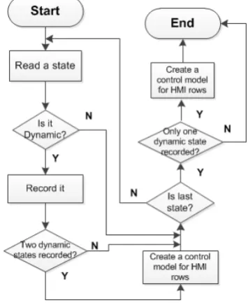
The workflow for Manual Control Model generation is shown in Fig. 4. As the manual control is only required for actuator components; therefore, the code generator analyses the state behaviour of actuator components only. Based on the state behaviour of each component, which is described as
[image:4.595.339.517.132.349.2]State Transition Diagram (STD), the static and dynamic states are identified and the static position pairs are created. The Manual Screen Generator within the HMI retrieves the data from Manual Control Model to create manual movement rows (pushbuttons) according to the static position pairs of actuators.
Fig. 4. Workflow of Manual Control Model generation
The Fault Management Model consists of machine faults and warning messages. The fault and warning messages are arranged according to their priority. Critical process states are triggered by the components and the logic engine, which are reported to the Fault Management Model. The Alarm Handler continually scans the Fault Management Model for active faults. In case of any active fault, the relevant text message is displayed on the operator screen.
The code generator exports the generated source code of the PLC software as a text file or XML format. The format of which should conform to the requirements of specific platform so that it can be directly imported into the vendor-specific engineering tools. The generation of the machine specific HMI is actually performed by the code generator within the PLC control program. Once the HMI software is downloaded to the HMI device then upon connection with the PLC the relevant data from the CDM within the PLC are retrieved to generate the resource specific screens and display diagnostic information. Any change in the Data Model is automatically tracked and the relevant functions dynamically update the operator screens, thus makes the HMI self-reconfigurable.
V. USE CASE
storage. For the use case, Siemens SIMATIC S7-300 and SIMATIC MP 277 HMI device were selected as the targeted hardware platform. The screen layouts were designed according to the ThyssenKrupp Krause System Engineering (TKSE) standards.
[image:5.595.307.560.172.300.2]The test rig was modelled and commissioned within the IET. The modelling consists of component assembly, definition of control behaviour of components, and finally the process logic to define the sequence of operations. The virtual prototype of the Festo test rig is shown in Figure 5. As an example, the respective state behaviour of a sensor component and an actuator component are also illustrated in the Fig. 5.
Fig. 5. Virtual prototype of the Festo rig and the state behaviour of its components modelled using IET
After virtual modelling and validation, the PLC code is generated and downloaded into the PLC. A generic SIMATIC WinCC project, designed according to the architecture described in the previous section is created and downloaded to the HMI device. Upon connection with the PLC, the HMI screens are automatically generated.
Fig. 6 shows the example screens created, consisting of home screen, manual movement screen and the fault diagnostic screen. The home screen is used to control the modes of operations of machine and navigate to other screens. The home screen is a generic screen and is essentially a manually created rather than automatically generated. This screen stays same for all machines.
Fig. 6. Generated HMI screens
The pushbuttons in the manual movement rows are created according to the static states within STD of the actuators defined within the IET. The number of rows on the HMI for controlling a specific component is determined by the static positions of a component. An example of two components – a pusher and a gantry, is shown in Fig. 7. For the component pusher, which has two positions, a HMI row is generated based on its state behaviour. The six states of the component gantry, three of which are dynamic states, are translated into two manual rows of the HMI.
[image:5.595.42.285.216.346.2]Fig. 7. Generating the manual mode screen based on the state behaviour of the corresponding components
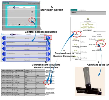
[image:5.595.317.542.348.553.2]Fig. 8. Workflow of HMI control
Fig. 8 demonstrates the runtime behaviours of the HMI and the PLC programs taking the actuator component Pusher as an example. When the pushbutton “WorkPosition” of the actuator pusher is pressed, the command is sent from the HMI to the corresponding Manual Control Model, which communicates with the RC “Act_Pusher”. Consequently, the RC processes the received command and writes the command to the connected output variable to drive the Pusher to move to its work position. The RC monitors the actuator and reports the current status of the actuator to the data model.
[image:5.595.50.231.553.688.2]reconfigured within IET then the cell information are re-imported in the Mapper. After necessary I/O configuration and Runtime Component mapping, the CDM for the reconfigured system is automatically updated. As the HMI software is generic therefore no changes are required in the HMI software. Upon connection with the PLC, the changes in the CDM inherently update the HMI screens.
VI. USE CASE
In this paper, an innovative approach to the development of HMI screens for component-based automation systems has been discussed. A component-based automation system was first virtually prototyped and commissioned in a 3D environment. Based on its validated virtual model, the screens are automatically generated and executed without any manual modifications.
The case study shows, that the dynamic approach to HMI creation offers advantages over the conventional static approach. It is more open to different platforms and easier to realise. It is envisaged that such an approach to develop the control software of an automation system can help to maximise the benefit of virtual commissioning by reducing the software development time. Furthermore, it will lead to enhanced agility, flexibility and reusability, and hence is potentially able to meet the user requirements in this current business context.
ACKNOWLEDGMENT
The authors gratefully acknowledge the support of the TSB and EPSRC through the 3Deployment and KDCM R&D projects and all the collaborators (in particular Ford Motor Company and ThyssenKrupp System Engineering) in carrying out this research.
REFERENCES
[1] I. Haq, T. Masood, B. Ahmad, R. Harrison, B. Raza, and R. Monfared, "Product to process lifecycle management in assembly automation systems," in 7th CIRP international conference on
digital enterprise technology, Athens, Greece, 2011, pp. 476-486.
[2] Y. Koren, U. Heisel, F. Jovane, T. Moriwaki, G. Pritschow, G. Ulsoy, et al., "Reconfigurable Manufacturing Systems," CIRP
Annals - Manufacturing Technology, vol. 48, pp. 527-540, 1999.
[3] M. G. Mehrabi, A. G. Ulsoy, and Y. Koren, "Reconfigurable manufacturing systems: Key to future manufacturing," Journal of
Intelligent Manufacturing, vol. 11, pp. 403-419, 2000.
[4] S. M. Lee, "A component-based distributed control paradigm for manufacturing automation system," PhD, Wolfson School of Mechanical and Manufacturing Engineering, Loughborough University, Leicestershire, 2004.
[5] M. Bergert, C. Diedrich, J. Kiefer, and T. Bar, "Automated PLC software generation based on standardized digital process information," in Emerging Technologies and Factory Automation,
2007. ETFA. IEEE Conference on, 2007, pp. 352-359.
[6] K. David, "Virtual commissioning of factory floor automation: the new paradigm in vehicle manufacturing," presented at the SAE 2010 world congress & exhibition, Detroit, USA, 2010.
[7] R. Harrison, D. Vera, S. McLeod, and A. Jain, "Virtual commissioning methods and tools," Loughborough University and Airbus, Internal Report2012.
[8] X. Kong, B. Ahmad, R. Harrison, Y. Park, and L. J. Lee, "Direct deployment of component-based automation systems," in
Emerging Technologies & Factory Automation (ETFA), 2012
IEEE 17th Conference on, 2012, pp. 1-4.
[9] K. Andersson, J. Richardsson, B. Lennartson, and M. Fabian, "Coordination of Operations by Relation Extraction for Manufacturing Cell Controllers," Control Systems Technology,
IEEE Transactions on, vol. 18, pp. 414-429, 2010.
[10] S. Lee, M. A. Ang, J. Lee, L. Lee, and D. M. Tilbury, "Automatic generation of logic control," Loughborough University, University of Michigan and Ford Motor Company2006.
[11] A. W. Colombo, F. Jammes, H. Smit, R. Harrison, J. L. M. Lastra, and I. M. Delamer, "Service-oriented architectures for collaborative automation," in Industrial Electronics Society, 2005.
IECON 2005. 31st Annual Conference of IEEE, 2005, p. 6 pp.
[12] M. H. Ong, "Evaluating the impact of adopting the component-based system within the automotive domain," PhD, Wolfson School of Mechanical and Manufacturing Engineering, Loughborough University, Leicestershire, 2004.
[13] R. Drath and M. Barth, "Concept for interoperability between independent engineering tools of heterogeneous disciplines," in
Emerging Technologies & Factory Automation (ETFA), 2011
IEEE 16th Conference on, 2011, pp. 1-8.
[14] B. Bohm, N. Gewald, A. Kohlein, and J. Elger, "Mechatronic models as a driver for digital plant engineering," in Emerging Technologies & Factory Automation (ETFA), 2011 IEEE 16th
Conference on, 2011, pp. 1-8.
[15] L. J. Lee, "A next generation manufacturing control system for a lean production environment," PhD, Wolfson school of mechanical and manufacturing engineering, Loughborough University, Leicestershire, 2004.
[16] A. Jain, D. Vera, and R. Harrison, "Virtual commissioning of modular automation systems," presented at the 10th IFAC workshop on intelligent manufacturing systems, Lisbon, Portugal, 2010.
[17] M. Bergert and J. Kiefer, "Mechatronic data models in production engineering," presented at the 10th IFAC Workshop on Intelligent Manufacturing System, Lisbon, Portugal, 2010.
[18] J. Richardsson and M. Fabian, "Automatic generation of PLC programs for control of flexible manufacturing cells," in Emerging Technologies and Factory Automation, 2003. Proceedings. ETFA
'03. IEEE Conference, 2003, pp. 337-344 vol.2.
[19] R. Drath, P. Weber, and N. Mauser, "An evolutionary approach for the industrial introduction of virtual commissioning," in Emerging Technologies and Factory Automation, 2008. ETFA 2008. IEEE
International Conference on, 2008, pp. 5-8.
[20] X. Kong, B. Ahmad, R. Harrison, A. Jain, Y. Park, and L. J. Lee, "Realising the open virtual commissioning of modular automation systems," in 7th CIRP International Conference on Digital
Enterprise Technology, Athens, Greece, 2011.
[21] R. Harrison, A. Colombo, A. West, and S. Lee, "Reconfigurable modular automation systems for automotive power-train manufacture," International Journal of Flexible Manufacturing