Design of Circular Split Ring Resonator in form of Dollar Symbol for
Wireless Application
Er. Atul Mahajan
1, Er. Parwinder Kaur
2, Er. Ashish Chand
31M.Tech, Scholar, Department of Electronic & Communication Engineering, Shiv Shankar Institute of Engineering & Technology, Patti.
2Assistant Professor, Department of Electronic & Communication Engineering, Shiv Shankar Institute of Engineering & Technology, Patti.
---***--- Abstract –The present paper describe the CSRR inform of Dollar Symbol shaped Multiband Microstrip patch antenna satisfying wireless applications. This paper takes research on design of multiband Microstrip Patch Antenna. The Proposed patch antenna can resonate at four unique frequencies between 4GHz and 9GHz out of which two are considered to be useful bands. The circular SRR is designed and then united with dollar symbol to make a new design. The proposed antenna is designed on FR4 Epoxy substrate with specifications: relative permittivity = 4.4, relative permeability = 1, di-electric loss tangent =0.02 and thickness = 1.6 mm .The return loss for all the resonant frequencies is less than -10dB. The proposed design exhibits the overall gain of 9.0 dB on other hand, individual gain of antenna is 2.7 dB at 7.54 GHz and 9.0 GHz respectively in the final iteration, and is used for many satellite communications transmissions, some Wi-Fi devices, some cordless telephones as well as some surveillance and weather radar systems.
Index Terms— MPA, Feeding techniques, Return loss and Gain.
I. INTRODUCTION
Antennas are a device which is used for wireless communication between two or more stations by transmitting signals from one station to another [1]. A microstrip patch antenna (MPA) is made of thin di-electric substrate with the ground of metallic material such as copper, gold. Now-a-days the need of wireless communication has grown [2]. Wireless systems are required to be small in size due to its characteristics to be mobile. Microstrip patch antenna is the major allure for researchers over the past work because their structures are probably easy to fabricate. Research on microstrip antenna in the 21st century if focused at small sized, increased gain, wide bandwidth, multiple functionality. To meet such features and requirements, the microstrip patch antenna have been proposed because of its low profile, less in cost, small in size [1]. Microstrip Patch Antenna consists of rectangular patch which is conductor in nature of length "L" and width "W" on one side of dielectric substrate with the thickness of "h" and dielectric constant "εr" with the base named ground. Parameters like return losses, gain and VSWR are calculated in this paper. Return loss or reflection loss is the reflection of signal power from the insertion of a device in a transmission line or optical fiber. Whereas, antenna gain is the ratio of maximum radiation intensity at the peak of main beam to the radiation intensity in the same direction produced by an isotropic radiator or omni - directional antenna having the same input power. Isotropic antenna is standardized to have a gain of unity. These methods are categorized into contacting and non-contacting technique. Generally contacting methods are microstrip line feeding and co-axial plane feeding. On other hand, non- contacting techniques are proximity coupled feeding, aperture coupled feed. We are using branch line feeding technique because it gives less return losses, is reliable and easy to fabricate.
II. ANTENNA DESIGN
Table 1: Dimensions of CSRR antenna design for 5GHz frequency
S.NO Description Values
1 Width of Patch 30mm
2 Length of Patch 30mm
3 Width of Substrate 40mm
4 Length of Substrate 40mm
5 Height of Substrate 1.6mm
6 Length of feed line 5mm
7 Width of feed line 3mm
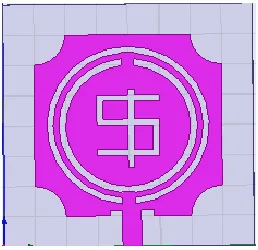
[image:2.612.365.498.295.419.2]The figure below shows the simulated antenna design using HFSS software and represent three different iterations. Now in order to improve its parameters we have etched rectangular slot and introduce new type of feeding technique as shown in figure 1. Here we observed the return loss is improved to -12.0 dB by introducing this slot in inset line feed. Further results will be discussed in this thesis.
Figure 1: 1st Iteration of Proposed Antenna Figure 2: 2nd Iteration of Proposed Antenna
The 2nd iteration of proposed antenna has been designed by taking all the dimensions same as the 1st iteration but in 2nd
iteration CSRR slot is extracted from the centre of rectangular patch. The length and width of the rectangular slot is 30mm and 30mm respectively. The simulated structure of 2nd iteration is given above.
The 3rd iteration of proposed antenna has been designed by taking all the dimensions same as the 2nd iteration but in 3rd
iteration CSRR slot is extracted from dollar symbol.
Figure 3: 3rd Iteration of Proposed Antenna
III. RESULTS AND DISCUSSION
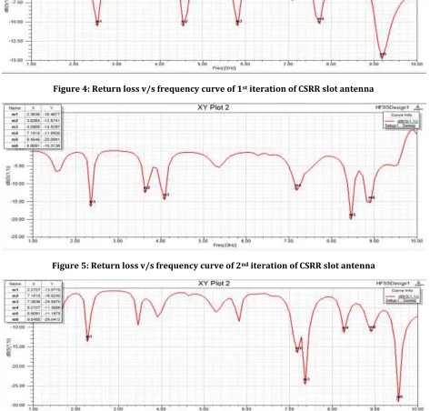
[image:2.612.242.371.528.653.2]Return loss
The return loss is the ratio of reflected power over transmitted power. The acceptable value of return loss is below -10dB for the antenna to work efficiently. The return loss v/s frequency curve for 1st, 2nd and 3rd iteration of Circular Split Ring Resonator
[image:3.612.74.541.161.312.2](CSRR) slot antenna is shown in Figure 4, 5 and 6 respectively.
[image:3.612.71.544.233.685.2]Figure 4: Return loss v/s frequency curve of 1st iteration of CSRR slot antenna
[image:3.612.74.540.457.685.2]Figure 5: Return loss v/s frequency curve of 2nd iteration of CSRR slot antenna
VSWR is Voltage Standing Wave Ratio it shows the impedance mismatch between the feeding system and antenna. VSWR v/s frequency curve for 1st, 2nd and 3rditeration of CSRR slot antenna is shown in Figure 7, 8 and 9 respectively.
Figure 7: VSWR v/s frequency curve of 1st iteration of CSRR slot antenna
Figure 8: VSWR v/s frequency curve of 2nd iteration of CSRR slot antenna
Figure 9: VSWR v/s frequency curve of 3rd iteration of CSRR slot antenna
IV. GAIN AND DIRECTIVITY
[image:4.612.79.541.131.250.2]Figure 10: 3D gain and Directivity plot of 1st iteration of CSRR slot antenna at 5GHz Frequency
Figure 11: 3D gain and Directivity plot of 2nd iteration of CSRR slot antenna at 5GHz Frequency
Figure 12: 3D gain and Directivity plot of 3rd iteration of CSRR slot antenna at 5GHz Frequency
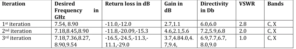
Table 2: Comparison of simulated results of 0th, 1st and 2nd iteration of circular slot antenna
Iteration Desired
Frequency in GHz
Return loss in dB Gain in
dB Directivity in Db VSWR Bands
1st iteration 7.54, 8.90 -11.0,-12.0 2.7,1.1 6.0,6.0 2.8 C, X
2nd iteration 7.18,8.45,8.90 -11.8,-20.09,-15.3 4.6,2.1,5.6 7.2,5.9,6.8 2.0 C, X
3rd iteration 7.18,7.36,8.27,
[image:5.612.152.460.447.584.2] [image:5.612.51.568.637.723.2]Conclusion
In this paper the attempt has been made to design antenna for C and X band applications. This work takes research on design of multiband microstrip patch antenna. The proposed patch antenna can resonate at seven unique frequencies between 2 GHz and 5 GHz out of which four are considered to be useful bands. The circular patch is designed and then united with more circles to make a new design. The proposed antenna is designed on FR4 Epoxy substrate with specifications: relative permittivity = 4.4, relative permeability = 1, di-electric loss tangent =0.02 and thickness = 1.6 mm .The return loss for all the resonant frequencies is less than -10dB. The proposed design exhibits individual gain of 9.0 dB at 9.54 GHz. The proposed antenna can be used for wireless applications wireless broadband transceiver which is applicable to mobile Wi max, fixed Wi max, RADAR applications including continuous wave pulsed, single polarisation, dual polarisation and air traffic control.
References
[1] M.Sahoo, S.Pattnaik and S.Sahu, ”Design of compact UWB hexagonal monopole antenna with frequency notch characteristics,” International Conference on Circuit, Power and Computing Technologies (ICCPCT), 2015.
[2] Y. Kumar and S. Singh, “A Quad band hybrid fractal antenna for wireless applications,” IEEE, International Advance Computing Conference (IACC), pp. 730-733, 2015.
[3] M. M. M. Ali, A. M. Azmy and O. M. Haraz, “Design and implementation of reconfigurable quad-band microstrip antenna for
MIMO wireless communication applications,” IEEE 31st National Radio Science Conference (NRSC), pp. 27-34, 2014.
[4] F.Daneshmandian, P.Dekhoda and A.Tavakoli,”A miniaturization circularly polarised microstrip antenna for GPS
applications,” IEEE 22nd Iranian Conference on Electrical Engineering (ICEE), pp.1653-1656,2014
[5] M.Susila.T.R.Rao and A.Gupta, ”A novel fractal antenna design for UWB wireless communications,”IEEE, International Microwave and RF Conference (IMaRC),pp.118-120,2014.
[6] N.Prema, Anil Kumar, “Design of multiband microstrip patch antenna for C and X” , optik 127 (2016)8812-8818.
[7] P.S. Bakariya, S. Dwari, M. Sarkar, M.K. Mandal, ”Proximity-Coupled microstrip antenna for bluetooth, WiMAX, and WLAN applications,” IEEE AntennasWirel. Propag. Lett. 14 (2015).
[8] S.Behera and D.Barad, “A novel design of microstrip fractal antenna for wireless sensor network,” IEEE, Inernational Confrence of Power, Energy, Information and Communication, pp. 0470-0474, 2015.
[9] T.Landeau, O.Losito, G.Palma, V.Portosi, A. Jouanneaux and F.Prudenzano, ”Multiband Rohmbus Monopole
Antenna,” GeMic, pp.367-370, 2015.
[10] V.vaid and S.Agarwal,”Bandwidth optimization using fractal geometry on rectangular microstrip patch antenna with DGS for wireless applications,” International conference on medical Imaging, M-health and Emerging Communication Systems (MedCom), pp.162-167, 2014.
[11] V.D.Raj, A.M.Prasad, M.Satyanarayana and G.M.V. Prasad, “Implementation of printed microstrip apollonian gasket fracxtal antenna for multiband wireless applications,” IEEE, International Conference on SPACES, pp.200-204, 2015.