http://www.scirp.org/journal/jcc ISSN Online: 2327-5227 ISSN Print: 2327-5219
DOI: 10.4236/jcc.2018.61028 Jan. 11, 2018 284 Journal of Computer and Communications
Stable Vibration-Based Communication Scheme
Using Multi-Step ASK and PPM Techniques
Keishi Usa1, Eiji Kamioka1, Khaironi Yatim Bin Sharif2
1Graduate School of Engineering and Science, Shibaura Institute of Technology, Tokyo, Japan
2Department of Software Engineering and Information System, University Putra Malaysia, Selangor, Malaysia
Abstract
In the information-oriented society, there are increasing needs to conduct da-ta communication with nearby devices/people. In this light, vibration-based com-munication method was proposed as one of possible comcom-munication means be-tween adjacent devices. This method has been expected to provide an intuitive and safe communication by propagating vibration to a receiver device. This study proposes two types of techniques, which are multi-step ASK (Amplitude Shift Keying) with pseudo clock and PPM (Pulse Position Modulation), to achieve a stable vibration-based communication simply using smart device functions. These proposed techniques are then evaluated through some experiments using sev-eral types of smart devices. In addition, the effectiveness of the proposed me-thods is discussed based on the experimental results.
Keywords
Smartphone, Communication Method, Vibration Motor, Acceleration Sensor
1. Introduction
In the information-oriented society, opportunities to conduct data communica-tion with nearby people or devices have increased. Furthermore, users who own multiple devices often exchange information between their devices. This requires high frequency of connection and fast connectivity (such as NFC, Wi-Fi and Bluetooth, refer to Section 2) which are normally costly and also exposed to var-ious security threat. Given the scenario, it is suggested to create a simple, easy and secured communication method.
In this light, vibration-based communication is proposed as one of possible com-munication means between adjacent devices. In this comcom-munication method,
sig-How to cite this paper: Usa, K., Kamioka, E. and Sharif, K.Y.B. (2018) Stable Vibra-tion-Based Communication Scheme Using Multi-Step ASK and PPM Techniques. Jour-nal of Computer and Communications, 6, 284-300.
https://doi.org/10.4236/jcc.2018.61028
Received: December 26, 2017 Accepted: January 8, 2018 Published: January 11, 2018
Copyright © 2018 by authors and Scientific Research Publishing Inc. This work is licensed under the Creative Commons Attribution International License (CC BY 4.0).
DOI: 10.4236/jcc.2018.61028 285 Journal of Computer and Communications
nals are transmitted by propagating vibration. Receiver device is able to receive these signals by simply touching vibrating parts of the sender device. Hence, this suggests a very simple and intuitive communication. In addition, the vibration re-ceivers can be easily identified since they must exit in the range where the vibra-tion can reach. It means that it is possible for the sender to limit the receivers that can receive the signals. This in turn suggests a convenient and secured communi-cation offered by vibration-based communicommuni-cation.
Yonezawa T., Nakazawa J., and Tokuda H. [1] proposed a vibration-based com-munication method using only functions of a smartphone. In this study, signals are generated by a vibration motor and detected by a three-axis acceleration sensor, which are built in a smartphone. The signal modulation is On-Off Keying (OOK) which regards the state when the device is vibrating and the state when the de-vice is not vibrating as 1 bit digital signal (1)2 and (0)2. However, when the device
is strongly vibrating, it takes time for the vibration to converge after the vibra-tion motor stops. It significantly influences the communicavibra-tion accuracy. Specifi-cally, there is an undesirable possibility that communication accuracy decreases when the communication speed is increased. Considering the problem of this con-vergence time, in this paper, two types of vibration signal modulation techniques are proposed for a stable vibration-based communication. These two modula-tions have not as yet been discussed before in the vibration-based communica-tion.
The contributions of this study are divided into two: 1) to propose and realize both a multi-step ASK (Amplitude Shift Keying) with pseudo clock and a PPM (Pulse Position Modulation) in the vibration-based communication, 2) to inves-tigate the feasibility of the proposed schemes using a variety of smart devices.
The rest of this paper is organized as follows: In Section 2, literature review related to short range communication and vibration-based communication will be described. In Section 3, the proposed methods will be fully explained. The performance evaluation of the proposed methods will be stated in Section 4 and the discussion based on the results of the evaluation will be done in Section 5. Finally, this paper will be concluded in Section 6.
2. Literature Review
In this section, review on various short range communication is presented to-gether with discussions on vibration-based communication to clarify problems in each communication method.
2.1. Short Range Communication Method
In order to perform a communication between adjacent devices there are various kinds of communication methods. These communication methods are briefly discussed in this section.
2.1.1. Near Field Communication
DOI: 10.4236/jcc.2018.61028 286 Journal of Computer and Communications
Field Communication (NFC) [2]. In NFC, signals can be transmitted between NFC tagged devices by locating them close to each other. NFC technology allows com-munications at a distance of about 10 cm with 424 kbps communication speed
[3]. This short distance allows the communication with adjacent devices. NFC is popularly used for electronic money transfer.
2.1.2. Bluetooth
While NFC enabling communications of about 10 cm distance, Bluetooth tech-nology allows further distant communications about several meters with 24 Mbps. This communication method is claimed as low power consumption and simul-taneous communication with multiple devices [4] [5] [6] [7]. These features are suitable for input/output devices for computer such as wireless mouse, wireless keyboard and wireless earphone.
2.1.3. Wi-Fi
On the other hand, Wi-Fi provides options for communication between devices up to 20 meters [6] [7]. Wi-Fi utilizes the radio frequency bands of 2.4 GHz and 5 GHz to provide a higher communication speed up to 6.9 Gbps. Wi-Fi makes a rich data transfer possible such as multimedia data.
2.1.4. Vibration-Based Communication
Vibration-based communication is a communication method that transmits da-ta by propagating solid vibration [1] [8]-[13]. In this method, receiver devices get transmitted data by touching the vibrating solid medium. Unlike the other wireless communication, it has the feature that information is not propagated to untouched devices. This method is mainly used for sending small information such as password and URL address.
2.1.5. Significance of Vibration-Based Communication
In reviewing all short range communication technologies, there is one obvious characteristic, namely, security threat. Specifically, NFC, Bluetooth and Wi-Fi are utilizing magnetic wave and radio signals. Hence, anyone within a certain range with some wireless devices can attempt to access the network (eavesdropping). NFC, for example, as reported in security article [14] data from credit cards are easily copied using NFC enabled device. On top of that, the open source nature of sys-tem development for Android OS allowing contributions from third parties ex-poses users to the risk of information stolen.
DOI: 10.4236/jcc.2018.61028 287 Journal of Computer and Communications
In relation with wave used for data transfer, there is another advantage of vi-bration-based communication, that is to say, it only uses physical vibration for com-munication. Thus, no magnetic electronic wave interference occurs. This feature brings more advantages since it can be used for communication for users who wear medical devices embedded in their body [9].
In terms of usability, NFC, Bluetooth and Wi-Fi require many preparations since each device must be connected before signal transmission is performed [4] [5] [6] [7] [15]. On the other hand, vibration-based communication does not need any preparation before the communication and information can be trans-mitted simply and easily. This suggests a higher significance of vibration-based communication.
2.2. Existing Vibration-Based Communication System
Given the significance of vibration-based communication, details about this com-munication technology are discussed in this section.
Human is able to recognize vibration signal by just touching vibrating place. Utilizing this point, some researchers conducted experiment to transmit data from device to user by device vibration pattern [10] [11]. In the same movement, the other researchers [12] [13] attempted a high-speed vibration-based commu-nication by using specific modules such as force reactors and piezo electric mo-tors. While these works show some lights in vibration-based communication, this approach is somehow impractical. Specifically, it is unrealistic to always carry such additional devices only for short range communication. Therefore, in this research, vibration-based communication is conducted by only using the functions imple-mented on smart devices.
Yonezawa T., Nakazawa J., and Tokuda, H. [1] have proposed a vibration-based communication method for smartphones [1]. In their study, signals are gener-ated by a vibration motor and detected by a three-axis acceleration sensor built in a smartphone. As a signal modulation method, On-Off Keying (OOK) me-thod utilizing device vibration state. In this approach, vibrating state is recog-nized as 1 bit digital signal (1)2 and not-vibrating state as (0)2. This method
of-fers an intuitive operation by simply stacking a sender device over a receiver de-vice and activating vibration motor. However, this method cannot achieve a high data rate communication. Suppose that some binary signals are frequently gen-erated. If two (1)2 signals are successively generated in a short time interval, the
second vibration signal may overlap with the first vibration signal, resulting in a significant communication error. This is because the second vibration signal is generated before the first vibration signal becomes small enough even the vibra-tion motor is inactivated.
DOI: 10.4236/jcc.2018.61028 288 Journal of Computer and Communications
critical problem since the data communication requires high communication ac-curacy.
In solving above problem Hwang I., Cho J., and Oh S. [8] proposed a more stable vibration communication method for smartphone. They have clarified one signal timing by continuously vibrating device to send one signal. In this case, smartphone vibrates in longer time-span than the previous method. In this setting, with a powerful vibration motor, the sender device is able to communi-cate with devices at a distant position by propagating vibration via hard solid medium. However, longer vibration time-span for each data transmission means longer time to generate each signal, thus communication rate is quite slow such as 0.64 bps.
3. Vibration-Based Communication Using Two Types of
Modulations
In this paper, two types of modulation techniques, which contribute to the sta-bility and higher data rate in vibration-based communication, are introduced. One is multi-step ASK (Amplitude Shift Keying), and the other is PPM (Pulse Position Modulation). To achieve both ASK and PPM in vibration-based com-munication, the key is how to control the vibration amplitude. If the vibration strength on a smart device can be controlled programmatically, it would be the easiest way. However, there is no standard function in Android OS (Operating System) to control the voltage of vibration motor. Therefore, a new method, which changes the vibration motor activating time, is proposed in this study. Suppose that the vibration motor is activated to make a vibration but it is soon inactivated before it reaches the full activation. In this situation, the generated vibration amplitude is smaller than the one generated by the full activation. This method enables to control the vibration amplitude without relying on Android standard Application Programming Interface (API). When a vibration motor is fully activated, the maximum vibration amplitude is generated. In the existing vibration-based communication, the maximum vibration altitude is always dis-cussed because the generated vibration can reach as far place as possible. How-ever, no research focuses on making the vibration amplitude smaller even though it can contribute to both the communication accuracy and high data rate commu-nication.
In the following subsections, the above mentioned two types of modulation techniques are described.
3.1. Multi-Step Amplitude Shift Keying (ASK)
In this subsection, a vibration-based communication using multi-step ASK (Am-plitude Shit Keying) with pseudo clock is proposed.
3.1.1. Multi-Step ASK Signal Generation with Pseudo Clock
DOI: 10.4236/jcc.2018.61028 289 Journal of Computer and Communications
ASK is the number of signal types. OOK introduces only two types of signals, which are “vibrating” and “not vibrating”. On the other hand, the proposed mul-ti-step ASK introduces several types of signals. The proposed method to generate different vibration amplitude requires a sensitive smart device control. The gen-erated vibration amplitude depends on the vibration motor activating time as mentioned above. However, it is also influenced by the vibration motor activat-ing interval. Here, the vibration motor activatactivat-ing interval is defined as the time interval from the time when the vibration motor is inactivated to the time when it is re-activated again. If the vibration motor activating interval is very large, the vibration motor completely stops. I this case, even though the vibration motor is re-activated with the given vibration motor activating time, sometimes a suffi-cient vibration amplitude is not generated. To solve this problem, “pseudo clock”, which is a vibration signal with a certain value of amplitude, is introduced. The pseudo clock is periodically inserted to keep the vibration motor activating in-terval shorter enough to generate a sufficient vibration amplitude for the subse-quent signal.
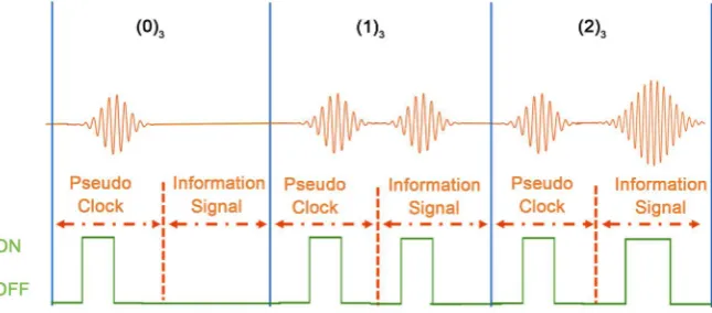
Figure 1 shows the proposed multi-step ASK signals generation with pseudo clock. Information signal in Figure 1 is the data which is transmitted to the re-ceiver. Each pulse in the figure depicts the vibration motor activating time. In this study, three types of signal values are considered, which are (0)3, (1)3 and
(2)3 corresponding to no amplitude, small amplitude and large amplitude,
re-spectively. As shown in Figure 1, a small amplitude vibration signal is periodi-cally inserted as a pseudo clock which has the same vibration amplitude as (1)3.
By inserting the pseudo clock periodically, the vibration motor does not com-pletely stop even though signal (0)3 is successively generated. In this approach,
[image:6.595.214.537.565.707.2]the pseudo clock is always inserted just before the information signal, hence, both pseudo clock and information signal can be extracted separately. Theoreti-cally it is possible to make more steps in ASK such as four steps and five steps. However, the more steps are introduced, the less communication accuracy is achieved. Therefore, only three-step ASK is discussed in this paper. Even in the case of three-step ASK, at least 1.5 times higher data rate than OOK can be achieved.
DOI: 10.4236/jcc.2018.61028 290 Journal of Computer and Communications 3.1.2. ASK Signal Demodulation Method
Demodulation of the proposed multi-step ASK signals is performed based on the acceleration values detected by three axis acceleration sensor on a smart device. The absolute acceleration values are taken out and the difference between the absolute values and the gravitational acceleration was then emerged. These val-ues are regarded as the vibration amplitude. In the demodulation process, the largest vibration amplitude in a signal time is extracted. The three types of sig-nals, (0)3, (1)3 and (2)3, are then demodulated based on the vibration amplitude.
Here, the signal time is defined as the time assigned to a vibration signal.
The demodulation program installed on a receiver device prepares two data arrays to store the detected acceleration values of a pseudo clock and the ones of an information signal separately. The pseudo clock vibration and the informa-tion signal vibrainforma-tion are alternately generated in a signal time. Therefore, the demodulation program on the receiver device divides the obtained acceleration values in a signal time into the first half and the second half. After that, each data is stored in each separate array. In this study, the pseudo clock has the same vi-bration amplitude as the signal (1)3. Therefore, the array in which more (1)3
sig-nals are stored is regarded as the array for pseudo clock data and the other array is regarded as the array for information signal data.
In the previous vibration-based communication method, the timing between transmitting and receiving devices is not synchronized. This causes the deviation of modulation and demodulation timing between communicating devices. The timing deviation still occurs even when the proposed multi-step ASK is used. This is because a vibration motor and an acceleration sensor on a smart device cannot be controlled precisely enough. As a result, a pseudo clock vibration may straddle the pseudo clock part and an information signal part. In the proposed multi-step ASK, the demodulation is performed based on the largest vibration amplitude obtained in a signal time. Hence, the demodulation error or signal loss occurs at the timing of this problem. In order to solve this problem, a com-munication timing synchronization function by using the pseudo clock is intro-duced.
DOI: 10.4236/jcc.2018.61028 291 Journal of Computer and Communications 3.2. Pulse Position Modulation (PPM)
In this section, a vibration-based communication using PPM is proposed.
3.2.1. PPM Signal Generation
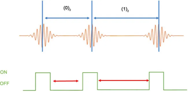
The vibration-based communication using PPM makes signals based on the time interval between adjacent vibrations. Therefore, only one type of vibration signal is needed in this method. Figure 2 shows an example of signal generation using PPM. As shown in Figure 2, the short and large time intervals indicate (0)2 and
(1)2 signals, respectively. The time interval can be controlled by changing the
vi-bration motor activating interval.
In the multi-step ASK signal generation, the pseudo clock is needed to stabil-ize the generated vibration amplitude. However, in the PPM signal generation, such a clock with no information is not needed since the vibration amplitude is not important if it can be detected correctly. Therefore, in this study, the same vibration amplitude as the signal (1)2 in the multi-step ASK is utilized since it
can converge faster, resulting in a higher data rate than the one using the signal (2)2. Figure 2 illustrates a two-step PPM signal generation. If a larger time interval
between adjacent vibration signals is introduced, three-step PPM can be realized. However, in this case, the data rate will be lower than the two-step PPM. Hereaf-ter, only two-step PPM is discussed.
3.2.2. PPM Signal Demodulation Method
Demodulation of the PPM signals is performed at the timing when the demodu-lation device detects a vibration signal. The vibration signal detection is con-ducted by confirming a certain level of vibration amplitude similar to the mul-ti-step ASK. When the vibration signal is detected, the time interval between ad-jacent vibration signals is calculated. Based on the time interval, two-step signal (0)2 or (1)2 is demodulated.
[image:8.595.212.538.546.711.2]In this modulation method, the demodulation processing is sequentially per-formed at the timing when a vibration signal is detected. Therefore, the receiver device does not have to perform a communication timing synchronization.
DOI: 10.4236/jcc.2018.61028 292 Journal of Computer and Communications
4. Evaluation
The practicality of the proposed method was evaluated by implementing it on smart devices as an Android application. In this section, the smartphone setting for performing the proposed communication method is explained. First, the re-sults of preliminary experiment are shown investigating the relation between de-vice operation and behavior in order to set appropriate parameters for nication. Next, the common device setting for using the proposed two commu-nication methods is described.
In this study, to confirm the versatility of the proposed method, two types of smartphones (Nexus 6 made by Motorola and AQUOS ZETA made by SHARP) and two types of tablet computers (Nexus 9 made by HTC and Media Pad M 3 made by HUAWEI) were prepared. In the preliminary experiment, Nexus 6 was utilized. Based on this result, suitable communication parameters for the two modulation schemes were set.
4.1. Preliminary Experiment
In this section, the result of preliminary experiment is shown. In order to set ap-propriate parameters for activating the vibration motor, this preliminary expe-riment investigates the relation between device operation and behavior. The movement of smartphone vibration motor changes due to the inertia of the pre-vious vibration. Therefore, even when a constant vibration motor activating time is set, the generated vibration amplitude was sometimes different. Because of that, when performing vibration-based communication, it is necessary to set the appropriate vibration motor activating time and vibration motor activating in-terval.
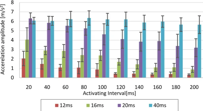
In the preliminary experiment, the vibration feature was measured by gene-rating smartphone vibration. Then, this vibration was detected by the accelera-tion sensor which is also implemented in the vibrating device. Data acquisiaccelera-tion frequency was set to SENSOR_DELAY_FASTEST which is a parameter defined in Android standard APIs. Acceleration data is output at the highest speed with this setting. Measurements of generated vibration were made at vibration motor activating interval from 20 ms to 200 ms every 20 ms. In each vibration motor activating interval, vibration activating time was set to 12 ms, 16 ms, 20 ms and 40 ms to measure the transition of the generated vibration amplitude. Vibration was generated 20 times in each parameter. After that, the amplitude and its gen-eration accuracy were measured.
Figure 3 shows the result of preliminary experiment. In this figure, the vertic-al and horizontvertic-al axes mean the generated vibration amplitude and set vibration motor activating interval, respectively. The vibration motor activating time was varied from 12 ms to 40 ms. Each data is plotted as the average acceleration am-plitude value of 20 times measurements and the error bar shows the standard deviation calculated from them.
DOI: 10.4236/jcc.2018.61028 293 Journal of Computer and Communications
Figure 3. Relation between vibration motor activating interval and generated vibration
amplitude varying vibration motor activating time.
with a short vibration motor activating time decreases when the vibration motor activating interval becomes longer. In particular, when the vibration motor acti-vating time was set to 12 ms, the generated vibration amplitude was greatly de-creased, depending on the vibration motor activating interval. The generated bration with this parameter cannot produce a sufficient amplitude when the vi-bration motor activating interval is long. Therefore, it is considered inappro-priate to set the vibration motor activating time to 12 ms or less as a parameter to generate vibration signals.
4.2. Smart Devices Setting for Vibration-Based Communication
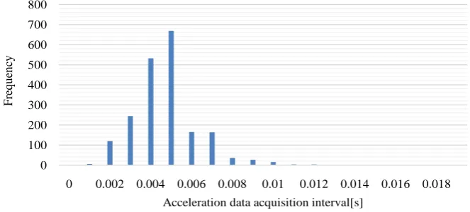
In this section, common smart device setting to conduct vibration-based com-munication is shown. In order to perform a vibration-based comcom-munication, acceleration data acquisition frequency was set to SENSOR_DELAY_FASTEST the same as the preliminary experiment. However, there is a problem that the measurement interval is unstable depending on the performance of each device when the acquisition interval is shortened [16]. Figure 4 shows the acceleration data acquisition interval histogram in SENSOR_DELAY_FASTEST when the acceleration value was obtained 2000 times. The used device in this experiment was NEXUS 6. In the figure, the vertical and horizontal axes mean the number of acquired sensor values in this interval and the data acquisition interval, respec-tively.
Figure 4 shows that the acceleration data was acquired almost every 5 ms. However, it can be confirmed that the acquisition frequency of acceleration is fluctuated about 4 ms. Because the acceleration data can be acquired every 5 ms, it is possible to calculate a signal time by counting the number of acquired acce-leration data. However, in this proposed method, how accurately a signal time can be divided is a significant factor for improving the demodulation accuracy. Therefore, in this proposed method, the demodulation timing is decided based
0 1 2 3 4 5 6 7 8
20 40 60 80 100 120 140 160 180 200
Ac
cer
el
at
io
n a
m
pl
itude
[m
/s
2]
Activating Interval[ms]
DOI: 10.4236/jcc.2018.61028 294 Journal of Computer and Communications
Figure 4. Fluctuation of sensor data acquisition interval in Nexus 6.
on the reference acceleration determined at the timing of synchronization and the time at which the acceleration was acquired.
Table 1 summarizes the acceleration data acquisition interval when SENSOR_ DELAY_FASTEST parameter was set to each device.
From this table, the difference of acceleration data acquisition interval be-tween Nexus 6 and Nexus 9 is more than twice. Because of that, it is better not to measure the number of data acquired by the acceleration sensor but to measure a signal time based on the time of acquiring the acceleration data of the device. Moreover, the number of acceleration data obtained during a signal time affects the communication accuracy. Hence, the vibration motor activating time is set based on the value for Nexus 9 since it is the longest data acquisition interval and the vibration signal can sufficiently be detected.
Considering the versatility of the application, the same signal generation pa-rameter that can be used by all devices was set. However, the detected vibration on the receiver side greatly changed depending on the shape and size of the de-vice. Hence, the parameter to detect signal for each device was investigated.
Based on the settings made in this section and the result of the preliminary experiment, the proposed vibration-based communication was tested by operat-ing the smart devices appropriately.
4.3. Performance Evaluation of Proposed Methods
In this section, the results of evaluation experiments for the proposed two me-thods are discussed. First, the experimental results for the vibration-based com-munication using multi-step ASK with pseudo clock is stated. Subsequently, the experimental results for the vibration-based communication using PPM are dis-cussed.
4.3.1. Evaluation Result of Multi-Step ASK with Pseudo Clock
The system evaluation to the vibration-based communication using the proposed multi-step ASK with pseudo clock was conducted.
Based on the result of the preliminary experiment, the vibration motor acti-vating time was set to 16 ms and 40 ms. As an appropriate value in this setting,
0 100 200 300 400 500 600 700 800
0 0.002 0.004 0.006 0.008 0.01 0.012 0.014 0.016 0.018
F
req
u
en
cy
DOI: 10.4236/jcc.2018.61028 295 Journal of Computer and Communications
Table 1. Acceleration data acquisition interval with SENSOR_DELAY_FASTET.
Device Name Nexus 6 AQUOS Zeta Nexus 9 Media Pad M3 Acceleration Detection Interval 0.00435 0.00500 0.01012 0.01000
the vibration motor activating interval was set to 80ms or more. In these para-meters, even if the fluctuation of the amplitude is the three times of the standard deviation, the generated vibration amplitude can be distinguished. Hence, in this study, the vibration motor activating time of 16 ms was set to generate signal (1)3
and the pseudo clock vibration, and the vibration motor activating time of 40 ms was set to generate signal (2)3. In addition, since the pseudo clock and
informa-tion signal are generated with a vibrainforma-tion motor activating interval of 80 ms or more, a signal time was set to 240 ms. From the receiver device, the resynchro-nization was performed every time when 10 signals were demodulated.
To evaluate the proposed communication method, the communication between two Nexus 6 was performed by lapping them over each other, and the demodu-lation accuracy was checked by sending 1000 bits of random data.
Figure 5 shows a part of detected acceleration data from the receiver device during the communication. The vertical and horizontal axes indicate the de-tected amplitude of vibration signal and the elapsed time, respectively. The dashed line means the demodulation timing of the receiver device. In this figure, each signal was detected almost in the middle of a demodulation time and the interval of detected signal did not become out of alignment even though the time elapsed. This result shows that each amplitude of vibration signal was properly generated and the synchronous processing worked correctly. In this experiment, the communication accuracy of 96.0% was achieved under the transmission data rate of 6.3 bps.
Table 2 shows the result of measurement which investigated the generated vibration amplitude by prepared 4 kinds of smart devices. In the measurement, Nexus 6 was used as the standard device for detecting vibration. By putting Nexus 6 on the device that sends the signal, the generated vibration amplitude was meas-ured. The signal was generated 100 times from each device and the result is shown by the average amplitude of detected vibration.
DOI: 10.4236/jcc.2018.61028 296 Journal of Computer and Communications
Figure 5. Generated vibration amplitude by multi-step ASK with pseudo clock.
Table 2. Generated vibration amplitude by the proposed multi-step ASK with pseudo
clock.
Device Name Nexus 6 AQUOS Zeta Nexus 9 Media Pad M3 16 ms Motor Activation (m/s2) 0.32461 1.57359 0.04551 0.05839 40 ms Motor Activation (m/s2) 1.42212 1.62406 0.05196 0.22076
smartphones and thus the vibration did not reach the acceleration sensor prop-erly. Note that the communication accuracy was calculated by the following eq-uation:
[ ]
received sentCommunication accuracy % N 100
N
= × (1)
where, Nsent and Nreceived stand for the number of bit signals sent from the sender
device and the number of bit signals correctly received by the receiver device, respectively.
Most of demodulation errors are caused by the attenuation of vibration sig-nals. In addition, when the pseudo clock detection was failed during the resyn-chronization period, information loss occurred. This suggests that the lack of pseudo clock vibrations and the occurrence of noise are serious problems in the communication. In this case, optimal parameter setting does not work to solve this problem, and thus, some additional functions, such as adding a checksum to information and sending a signal retransmission request from the demodulation device, are required.
4.3.2. Evaluation Result of PPM
In this section, the evaluation result of the vibration-based communication with PPM is shown. When the vibration is generated by the vibration motor on the smartphone, the timing deviation may occur between the set vibration motor ac-tivating time and the timing at which the vibration is actually generated. The vi-bration signal was generated 2000 times on the smartphone and the fluctuation
0 0.5 1 1.5 2 2.5
28.5 29 29.5 30 30.5 31 31.5
Acce
le
ra
tio
n[
m
/s
2]
[image:13.595.209.540.322.368.2]DOI: 10.4236/jcc.2018.61028 297 Journal of Computer and Communications
of vibration signal generation timing was confirmed with the standard deviation of 19.92 ms at Nexus 6 and 14.56 ms at AQUOS Zeta. Considering the three times of the standard deviation of Nexus 6, 150 ms as the vibration motor acti-vating interval for generating the signal (0)2, and 270 ms to generate the signal
(1)2 were set, respectively. The vibration motor activating time for generating
[image:14.595.212.538.536.714.2]vibration signal was set to 40 ms. This vibration motor activating time can gen-erate vibration normally even if 270 ms vibration motor activating interval is provided. In addition, when using the proposed method, it is necessary to con-sider the convergence time of the vibration in order to distinguish whether the previous vibration has not converged yet or not. Therefore, 90mswas set to the vibration convergence time based on the detected vibration. With this conver-gence time, the vibration signal can be sufficiently distinguished from the next generated vibration.
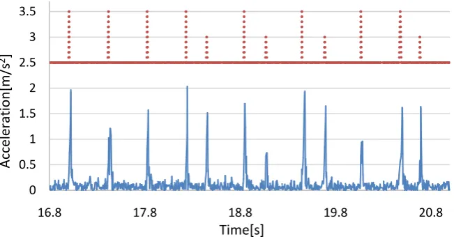
Figure 6 shows the acceleration data acquired by the receiver device when the vibration-based communication with PPM was performed between two Nexus 6. In the figure, the vertical axis indicates the amplitude of the detected accelera-tion and the horizontal axis indicates the communicaaccelera-tion time. The dashed line in the figure shows the demodulation timing of the receiver device and it also indicates the demodulation result. More concretely, the signal demodulation was performed at the timing when the broken line rises, and when the raised line is short, the signal (0)2 was demodulated and when it is long, the signal (1)2 was
demodulated. When communicating with two Nexus 6 using this proposed me-thod, 2000 signals were transmitted at the communication speed of 3.2 to 5.2 bps, and the communication accuracy of 100.0% was achieved.
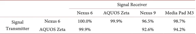
In the case of AQUOS Zeta, it was able to generate the vibration signal by the PPM. However, when trying to generate signals with tablet computers, the gen-erated vibration was not large enough, and the vibration could not be detected from other devices similar to the case of using multi-step ASK method. Table 3
shows the signal demodulation accuracy when Nexus 6 and AQUOS Zeta are used as signal transmission devices.
Figure 6. Generated vibration signal by PPM.
0 0.5 1 1.5 2 2.5 3 3.5
16.8 17.8 18.8 19.8 20.8
Acce
le
ra
tio
n[
m
/s
2]
DOI: 10.4236/jcc.2018.61028 298 Journal of Computer and Communications
Table 3. Communication accuracy with vibration-based communication with the PPM.
Signal Receiver
Nexus 6 AQUOS Zeta Nexus 9 Media Pad M3 Signal
Transmitter
Nexus 6 100.0% 99.9% 96.5% 98.7%
AQUOS Zeta 99.9% 92.6% 94.2%
In this experiment, we could not prepare two AQUOS Zeta. Because of that, the experimental result using AQUOS Zeta for both transmitting and receiving device is not shown in the table. When communicating using AQUOS Zeta as the signal transmitter, the size of the device is small, thereby the vibration can-not be propagated sufficiently to tablet computers. This results in the low com-munication accuracy. With this proposed method, Nexus 6 was able to commu-nicate with the prepared all devices with the communication accuracy of 98.7% on average. In addition, with regard to AQUOS Zeta, it was able to communicate with the prepared all devices with the accuracy of 95.6% on average. Note that the communication accuracy here is defined by the same equation as Equation (1) stated in Section 4.3.1.
In the experiment, sometimes vibration signals were not generated and it re-sulted in signal loss in the receiver device. Also, long time interval between two vibration signals also led to a demodulation error. Moreover, when vibration signals were generated frequently, the vibration did not converge sufficiently and some extra signals were miss-produced as the demodulation result. To overcome the demodulation error in the PPM, it is necessary to classify the signals based on the time interval between vibration signals.
5. Discussion
In comparing with multi-step ASK with pseudo clock, the communication using the PPM has a better performance with a higher accuracy. When performing communication with multi-step ASK, a stable communication environment is required. It is necessary to ensure that the sender device can generate plural steps of vibrations. On the other hand, the PPM can generate an enough vibration even though the amplitude is small. In addition, the signal can be demodulated easily if the vibration signal can be detected. However, the transmission data rate with the PPM is unstable and the transmission data rate itself is slower than the communication with multi-step ASK. Hence, it is important to select a suitable communication method for each device depending on the environment.
Both methods proposed in this paper have the robustness to vibration attenu-ation, especially PPM. However, it is difficult to solve the vibration noise prob-lem that is caused by the communication environment. To tackle this probprob-lem, it is necessary to introduce a noise removal process such as Fast Fourier Trans-form.
6. Conclusions
sta-DOI: 10.4236/jcc.2018.61028 299 Journal of Computer and Communications
bility and higher data rate in vibration-based communication, were proposed. One is multi-step ASK with pseudo clock method, and the other is PPM method.
The multi-step ASK with pseudo clock method with Nexus 6 achieved the com-munication accuracy of 96.0% at transmission data rate of 6.3 bps.
The PPM method with Nexus 6 achieved the communication accuracy of 98.7% at transmission data rate of 3.2 to 5.2 bps. When AQUOS Zeta was used as a transmission device, it performed the information transfer with the accuracy of 95.6%. The result of the evaluation experiment shows that the PPM method can perform the demodulation without drastically lowering the transmission data rate.
Most of the smart devices are equipped with an acceleration sensor and a vi-bration motor. Thus, the vivi-bration strength can be checked by the device itself. If a smartphone is capable to generate a sufficient strength of vibration, the multi-step ASK with pseudo clock method is applicable to execute the vibration-based com-munication. On the other hand, the PPM method is suitable for a smartphone with the capability of less vibration strength. In this way, the vibration-based communi-cation can be implemented by changing the method to the communicommuni-cation en-vironment based on the device capability.
As future works, automatic device capability detection schemes and killer ap-plications development will be investigated. The former is indispensable to per-form the proposed two types of modulation techniques and the latter is impor-tant to accelerate the vibration-based communication which will lead to a new mobile life-style.
References
[1] Yonezawa, T., Nakazawa, J. and Tokuda, H. (2015) Vinteraction: Vibration-Based Information Transfer for Smart Devices.2015 Eighth International Conference on
Mobile Computing and Ubiquitous Networking (ICMU), Hakodate, 20-22 January
2015, 155-160. https://doi.org/10.1109/ICMU.2015.7061059
[2] Fischer, J. (2009) NFC in Cell Phones: The New Paradigm for an Interactive World [Near-Field Communications]. IEEE Communications Magazine, 47, 22-28.
https://doi.org/10.1109/MCOM.2009.5116794
[3] Coskun, V., Ok, K. and Ozdenizci, B. (2013) Professional NFC Application Devel-opment for Android. John Wiley & Sons, Hoboken.
[4] Perrucci, G.P., Fitzek, F.H. and Widmer, J. (2011) Survey on Energy Consumption Entities on the Smartphone Platform. 2011 IEEE 73rd Vehicular Technology
Con-ference (VTC Spring), Yokohama, 15-18 May 2011, 1-6.
https://doi.org/10.1109/VETECS.2011.5956528
[5] Langston, J.L. (2000) Low Power, Short Range Point-to-Multipoint Communica-tions Systems. US Patent No. 6101174.
[6] Lee, J.S., Su, Y.W. and Shen, C.C. (2007) A Comparative Study of Wireless Proto-cols: Bluetooth, UWB, ZigBee, and Wi-Fi. 33rd Annual Conference of the IEEE
In-dustrial Electronics Society, Taipei, 5-8 November 2007, 46-51.
[7] Bhagwat, P. (2001) Bluetooth: Technology for Short-Range Wireless Apps. IEEE
DOI: 10.4236/jcc.2018.61028 300 Journal of Computer and Communications
[8] Hwang, I., Cho, J. and Oh, S. (2012) Privacy-Aware Communication for Smart-phones Using Vibration.2012 IEEE 18th International Conference on Embedded
and Real-Time Computing Systems and Applications (RTCSA), Seoul,19-22
Au-gust 2012, 447-452.
[9] Kim, Y., Lee, W.S., Raghunathan, V., Jha, N.K. and Raghunathan, A. (2015) Vibra-tion-Based Secure Side Channel for Medical Devices.2015 52nd ACM/EDAC/IEEE
Design Automation Conference (DAC), San Francisco, 8-12 June 2015, 1-6.
[10] Chang, A., O’Modhrain, S., Jacob, R., Gunther, E. and Ishii, H. (2002) ComTouch: Design of a Vibrotactile Communication Device. Proceedings of the 4th Conference
on Designing Interactive Systems: Processes, Practices, Methods, and Techniques,
London, 25-28 June 2002, 312-320. https://doi.org/10.1145/778712.778755
[11] Saket, B., Prasojo, C., Huang, Y. and Zhao, S. (2013) Designing an Effective Vibra-tion-Based Notification Interface for Mobile Phones. Proceedings of the 2013
Con-ference on Computer Supported Cooperative Work, San Antonio, 23-27 February
2013, 149-1504.
[12] Trigona, C., Andò, B., Baglio, S., La Rosa, R. and Zoppi, G. (2016) Vibration-Based Transducer for Zero-Energy Standby Applications. 2016 IEEE Sensors Applications
Symposium (SAS), Catania, 20-22 April 2016, 1-4.
https://doi.org/10.1109/SAS.2016.7479817
[13] Yonezawa, T., Nakahara, H. and Tokuda, H. (2011) Vib-Connect: A Device Colla-boration Interface Using Vibration. 2011 IEEE 17th International Conference on
Embedded and Real-Time Computing Systems and Applications (RTCSA),
Toya-ma, 28-31 August 2011, 121-125.
[14] Fox-Brewster, T. (2015) See How This Android App Clones Contactless Credit Cards in Seconds.
https://www.forbes.com/sites/thomasbrewster/2015/02/18/android-app-clones-card s/#4b4d8910db39
[15] Leeper, D.G. (2001) A Long-Term View of Short-Range Wireless. Computer, 34, 39-44. https://doi.org/10.1109/2.928620