Research Article
July
2017
Computer Science and Software Engineering
ISSN: 2277-128X (Volume-7, Issue-7)
Future Trends in 5g Wireless Communication: A Survey
Amit Rathee, Manu Phogat, MukeshDepartment of CSE GJUS & T, Hisar, Haryana, India
DOI: 10.23956/ijarcsse/V7I7/0138
Abstract– In modern era the exponential growth in smartphones with better applications need higher efficiency as compare with 4G devices. The data rate and spectrum efficiency is increasing day by day. Although 4G system provided much better services and better latency rate, there is still a gap between people’s requirements and what 4G system is providing. This article gives an overview of key enabling technologies which could be used in future 5G wireless systems. Some of these are Massive MIMO, Device-to-Device (D2D) communications, full duplex technique, millimeter wave communications, Internet of things (IoT) and Cloud RAN. By 2020 more than 9.2 billion devices will be there. And these key technologies will surely change the standards of future generation communication system.
Keywords- 5G, Massive MIMO, D2D communications, full duplex, millimeter wave communications, IoT, Cloud RAN.
I. INTRODUCTION
With increasing demand of phones, user demand for mobile broadband has also increased. Increasing in smart phones devices and the resulting exponential growth of data traffic has increased the need of higher data rates of wireless networks. The massive growth in the smart phones, tablets and the other data devices use extra capacity and higher spectral efficiency. Also, there are other strong drive from different industries like car and manufacturing industry, health and education sector and many more which exploit the uses of wireless networks. As per one estimate presented in [1], likely as many as 50 billion devices will be connected around 2020. These wireless devices are going to have very different characteristics in terms of processing capabilities, hardware and network structure. As well as, the nature of applications is also going to be diverse in terms of data rates and latency requirements. In near future, i.e. beyond 4G, some of the prime objectives that need to be addressed are expanded capacity, better data rate, decreased latency, and improvement in quality of service [4]. To meet these requirements, improvements need to be made in cellular network architecture [1]. It is expecting that 5th generation wireless mobile communication system will be launched around 2020. But it is not say anything with surety. Although one thing is clear that 5G will give better results in different areas like better bandwidth, signal strength, spectral efficiency, latency rate as compare with 4G.
Flat IP
Although ongoing 4th generation mobile network uses IPv6 over IPv4, but the problem of traditional hierarchical cellular system is the size of packet data is increasing in future generation wireless networks. Traditional BSC (Base stations controllers) uses these packet data sessions as same way as they treat voice sessions.While data packet sessions varies in size from few kbps to several gbps to download [17].However BSC manages all these session activities but the scaling is a major issue there. Flat IP Network get rid of these voice focused approach from network. Also BSC and RNC(Radio network controllers) are collapsed into base station itself, which are essential for IP router to communicate directly. While in Flat Internet Protocol traffic will directly travel from Base station to Media gateways [2]. A common IP platform for all called super core is establish to overcome the problem of connection establishment. Current wireless networks are designed on the basis of voice centric approach i.e. hierarchical manner. As data traffic is increasing by tremendous speed, voice centric hierarchical networks will face a great deal of congestion. Flat network architecture removesthis hierarchical manner and creates IP centric flat network architecture.
Device to Device Communication
ISSN(E): 2277-128X, ISSN(P): 2277-6451, DOI: 10.23956/ijarcsse/V7I7/0138, pp. 57-63
Fig.1 Showing device relaying information via other device
In 5G cellular networks, two types of D2D communications can be set up: local D2D communications and global D2D communications. In local D2D communications a path between two devices connected with the same base station, either directly or by relaying information through other devices. They discovered the closest devices and cut down the communication cost between these devices. On the other hand in global D2D communications two devices related with different base stations by bouncing through other networks. They summarize both base station to base station (B2B) communications & device-to-base station (D2B) communications [5].
Pricing of D2D communication
Pricing of D2D is also an important issue while considering device level communication, it’s a problem for operators how they control the pricing for D2D services. Indirect D2D communication, the devices needto have a protected and secure environment for the process interchange their resources among themselves.The service providers can control this Secureenvironment for better results.Therefore,it can expect that the users were charged for security and QoS reasons in D2D communication. The service provider can offer some free services instead the amount of packets the device relayed. For example the following serviceable function is characterized:-
𝑈𝑖 =𝑏𝑖log 2(1 + 𝑘𝑖𝛾𝑖)- M𝑏1𝑝𝑖+𝑏 log 2𝑖 (1+ 𝑘𝑖𝑦𝑖) [6]
Here 𝑏𝑖 is referredas channel bandwidth used by device and the revenue generate form this usages is 𝑏𝑖log 1(1 +𝑘𝑖𝛾𝑖).Here𝒌𝒊=1.5/In, it denotes the spectrum efficiency. 𝛾𝑖Denotes the average signal to noise ratio (SNR) for a link
between base station (BS) and the device. M denotes the number of hopes between the BS and the device for datatransmission. Where 𝑝𝑖denotes the price per unit of spectrum.𝑦𝑖Denotes the average SNR between BS and the device
while transmission data. Also if there are N devices for the same the revenue will be calculated as :-
R= 𝑁𝑖=1𝑀𝑏𝑖𝑝𝑖 - M𝑏 𝑝𝑖 𝑖[6]
Millimeter wave communications
In next 20 years, the explosive growth in data traffic, the use of mmwave frequencies from 20 GHz to 90 GHz will change the scenario of wireless communication. Technologies like mmwave & beamforming with large scale antennas are very appropriate for next era of 5G wireless networks [10].
There are essential difference between mmwave communication & other communication mediums in terms of blockage sensitivity, higher propagation loss & directive approach. Mmwave communication have been recommended as an important aspect of 5G network, as it provide HDTV and ultra HDTV features [20][21]. In current scenario the research is focused on 28 GHz band to 60 GHz band. While mmwave is a spectrum band lies between 30 GHz to 300 GHz [23]. MM wave is basically a line of sight (LoS) and also known as EHF & VHF by International Telecommunication Union. It has very short wavelength typically lies between 1 to 10 mm. Although there are outdoor effecting factors also like gases in atmosphere, rain & humidity [22].The current scenario of bandwidth and spectral efficiency is shown below:
Table 1 Current 2g, 3g, 4g, & Lte-A Bandwidth and Spectrum Efficiency [11] [12].
Band Uplink Downlink Spectrum Efficiency (MHz)
700 MHz 746-763 776-793 1-10
AWS 1710-1755 2110-2155 5-15
IMT Extension 2500-2570 2620-2690 5-20
ISSN(E): 2277-128X, ISSN(P): 2277-6451, DOI: 10.23956/ijarcsse/V7I7/0138, pp. 57-63
UMTS Core 1920-1980 2110-2170 5-10
GSM 1800 1710-1785 1805-1880 1-5
PCS 1900 1850-1910 1930-1990 1-5
Cellular 850 824-849 869-894 1-5
Digital Dividend 470-854 1-20
There are some Doppler results also there to calculate the carrier frequencies while device is moving at different angles [7] [24][25].The Doppler of a mmwave channel are depends upon the mobility speed and the carrier frequency. The maximum Doppler shift is given by
D= 𝑣.𝑓
𝑐
Where v=mobility speed f= carrier frequency [7] The result of this equation is given below
Table 2
Table 3
Carrier frequency (GHz)
Coherence Time (ms) 3 10 30 60 Mobility
speed (km/h)
3 120.00 36.00 12.00 6.00 30 12.00 3.60 1.20 0.60
120 3.00 0.90 0.30 0.15
350 1.03 0.31 0.10 0.50
At present the current maximum spectral efficiency is already obtained with MIMO (upto 8×8 Array). Therefor it will need better frequency bands with large amount of spectrum & better interface management schemes [8][19].
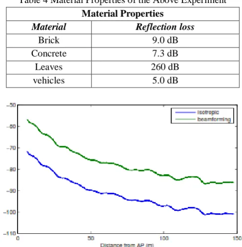
There are simulation results are available after practical access of E-band (light licensed 80 GHz) with Ray tracing simulation technique. The results are performed at 72 GHz in different material & in different areas i.e. small & urban [9].
In these following results, a 150 meters long & 20 meters wide street was used . Also stationary vehicles were parked there with total of approximately 60% of parking space are occupied. A 3D ray tracing simulation method was used for the given results. The antennas were placed above 8 meters heights on all four corners of the street, with a grid formation of 0.25×.025 meters [9].
Fig. 2Generated scene that was studied with the ray tracer. The bluespheres are Antennas, green boxes are leaves, and blue boxes are vehicles.
Carrier frequency(GHz)
Max. Doppler (Hz) 3 10 30 60 Mobility
speed (km/h)
3 8.3 27.8 83.3 166.7
ISSN(E): 2277-128X, ISSN(P): 2277-6451, DOI: 10.23956/ijarcsse/V7I7/0138, pp. 57-63 Table 4 Material Properties of the Above Experiment
Material Properties Material Reflection loss
Brick 9.0 dB
Concrete 7.3 dB
Leaves 260 dB
vehicles 5.0 dB
Fig.3 The average power received is shown against the distance from antenna .
Fig. 4System-level user equipment results
In current scenario due to high propagation loss in data & less cost-effective methods, these frequencies have mostly been used for outband point to point links
and for high beams used in indoor circumstances [13]. For proper utilization for future cellular networks the problem of large coverage of geographical area & NLoS must be handled [14] [18]. These two challenges may be overcome by recent simulation & experiments. There are a common misunderstanding that the propagation abilities of higher procreation loss even in free space as compared with lower frequencies. To make clear these misunderstandings we should look at Friss transmission equation [14].
𝑃𝑟 = 𝑃𝑡+ 𝐺𝑡+ 𝐺𝑟+ 20 𝑙𝑜𝑔 𝑐
4𝜋𝑅𝑓 [𝑑𝐵𝑚]
Where 𝑃𝑟 power in free space, 𝑃𝑡 is transmitted power, 𝐺𝑡 is transmitted antenna, 𝐺𝑟 is receiver antenna, 𝑅 is distance between these two antennas. 𝑐 is speed of light, 𝑓 is carrier frequency. This equation shows the propagation losses at different frequencies with power consumption. While the world is moving towards the millimeter Gigabit (MGB) per-second vision, techniques like mmwave & Massive MIMO will plays an important role to achieve these goals. There are new antennas arrays will be designed to make MGB possible [26].
Massive MIMO
ISSN(E): 2277-128X, ISSN(P): 2277-6451, DOI: 10.23956/ijarcsse/V7I7/0138, pp. 57-63 multi-user MIMO (MU-MIMO) system, in which multiple antennas deliver a single set of antenna with the help of BS. And then this gain is shared by all the users. In recent attempt of achieving more benefits from MU-MIMO, it is required to clarify the signal processing. And the solution is massive MIMO or Large-Scale Antenna System (LSAS) [27] [28].Massive MIMO technology has great potential i.e. it can increase the capacity by more than 10 times. And all this is possible because of uses the large number of antennas &spatial multiplexing of antenna. Massive MIMO is a game changer wireless technology with its implementationschemes. Also massive MIMO has degree of freedom. For example, with 4000 antennas serving 40 terminals, 180 degrees of freedom is untapped. This degree of freedom can be used later for shaping the signaling [29] [30]. The performance of wireless system is normally limited by declining. This happens when the proposed signal is sent by a base station through multiple directions before it reaches to the destination. This fading of data makes it hard to frame low latency links. Massive MIMO overcome this fading & latency problem by using large number of arrays&beam forming.
Channel modes for Massive MIMO
There are basically two channels models widely used for evaluate the performance of wireless communication system. a) CBSMs (Correlation based stochastic models)
b) GBSMs (Geometry based stochastic models)
CBSMs mainly used for evaluation of theoretical performance of massive MIMO system. This channel approach is mainly used for stationary environment and wave effects. It is not more suitable for Massive MIMO approach. There are three sub models are there in CBSMs.
1) Rayleigh channel model 2) Correlation channel model 3) Mutual coupling channel model
GBSMs area channel model designed for massive MIMO system with higher computation complications. This approach carries the performance evaluation of realistic analysis [32] [33].
There is sub category also to apply these channel approaches in GBSM given below a) 2D channel model
b) 3D channel model
In 2D channel model a propagate beam is penetrate on 2D plane i.e. in linear array. On the other hand on 3D channel model the beam is propagating on shapes like spherical, rectangular and cylindrical array [34]. While massive MIMO provide solution for many traditional problems in communication system, it also spread the research area of many uncovered problems likely:-
1) Within power consumption 2) The question of low-cost hardware.
3) Much more contamination as compare with traditional MIMO. 4) Cost of exchanging calibration for TDD.
5) Problem of characterize the correct radio channel model.
Massive MIMO has been one of the productive way to improve both energy & spectral efficiency for wireless communication system. However to get the benefits from massive MIMO significantly a number of issues including interface management, channel allocation, hardware excise and wave modulation should be considered.
Abbreviations
NLOS- Non Line of Sight Mmwave- Millimeter Wave EHF- Extremely High Frequency VHF- Very High Frequency TDD- Time Division Duplex
II. CONCLUSION
In this paper, an investigation of available key techniques for 5G underlying LTE network is done. With due to the massive increase in smart devices, these techniques are needed to be applied in many wireless devices for future monitoring and control. These techniques have huge potential to increase the channel and spectral capacity.
REFRENCES
[1] Robert Baldemair, Erik Dahlman, Gabor Fodor, Gunnar Mildh, Stefan Parkvall, Hugo Tullberg and Kumar Balachandran, Evolving wireless communications: Addressing the challenges and expectations of the future, IEEE Veh. Technol. Mag., vol. 8, no. 1, pp. 24-30, Mar. 2013.
ISSN(E): 2277-128X, ISSN(P): 2277-6451, DOI: 10.23956/ijarcsse/V7I7/0138, pp. 57-63 [3] LiljanaGavrilovska, ValentinRakovicand Vladimir Atanasovski, Visions Towards 5G: Technical Requirements
and Potential Enablers, Springer Science and Business Media, New York ,2015.
[4] Akhil Gupta, and R.K Jha, A Survey of 5G Network: Architecture and Emerging Technologies, IEEE Access, vol. 3,pp. 1206-1232, July 2015.
[5] JianQiao, XueminShen, Jon W. Mark, QinghuaShen, Yejun He and Lei Lei, Enabling Device-to-Device Communications in Millimeter-Wave 5G Cellular Networks, IEEE Communications Magazine, Vol. 53, Issue: 1,pp. 209-215, January 2015.
[6] Mohsen Nader Tehrani, Murat Uysal, and HalimYanikomeroglu ,Device-to-Device Communication in 5G Cellular Networks: Challenges, Solutions, and Future DirectionsIEEE Communications Magazine, Volume: 52, Issue: 5, May 2014 .
[7] Farooq Khan, Zhouyue Pi and Sridhar Rajagopal, Millimeter-wave Mobile Broadband with Large Scale Spatial Processing for 5G Mobile Communication, Fiftieth Annual Allerton Conference, Allerton House, USA, October 1 - 5, 2012.
[8] Mark Cudak, AmitavaGhosh, Thomas kovarik R Ratasuk, Moving Towards Mmwave-Based Beyond-4G (B4G)Technology, In Proc. IEEE VTC Spring, June 2013.
[9] Martin Jacob, Student Member,SebastianPriebe, Robert Dickhoff ,Thomas KleineOstmann and Thorsten Schrader, Diffraction in mm and Sub-mm Wave Indoor Propagation Channels, IEEE Transactions on , vol.60, no.3, pp.833-844, March 2012.
[10] Stephen G. Larew, Timothy A. Thomas, Mark Cudak, AmitavaGhosh, Air Interface Design and Ray Tracing Study for 5G Millimeter Wave Communications, Globecom Workshops, IEEE ,2013 .
[11] T. S. Rappaport, Wireless Communications: Principles and Practice, 2nd ed. Englewood Cliffs, NJ, USA: Prentice-Hall, 2002.
[12] Rakesh Kumar Bhatnagar, Guidelines for Evaluation of Radio Interference Technologies for IMT Advanced,Standard, ITU-R M.2135, 2008.
[13] Theodore S. Rappaport , Shu Sun, RimmaMayzus , Hang Zhao, Yaniv Azar1 , Kevin Wang , George N. Wong , Jocelyn K. Schulz , MathewSamimi , And Felix Gutierrez, Millimeter Wave Mobile Communications for 5G Cellular: It Will Work!, IEEE Access, vol. 1, May 2013, pp. 335–49, 2013.
[14] H. T. Friis, A Note on a Simple Transmission Formula, Proc. IRE 34, 1946, pp. 254–56.
15] Assessment of the Global Mobile Broadband Deployments and Forecasts for International Mobile Telecommunications, ITU-R tech. rep. M.2243, 2011.
[16] White paper, Cisco Visual Networking Index: Forecast and Methodology, 2012 2017, Cisco VNI Report, May
2013, http://www.cisco.com/en/US/solutions/collateral/
341/ns525/ns537/ns705/ns827/white_paper_c11481360.pdf.
[17] Akhilesh Kumar Pachauri and Ompal Singh , 5G Technology – Redefining wireless Communication in upcoming years, International Journal of Computer Science and Management Research, Vol. 1, pp.12-19, 2012. [18] Geng, S. Y., Kivinen, J., Zhao, X. W. and Vainikainen, Millimeter-wave propagation channel characterization
for short range wireless communications, IEEE Transactions on Vehicular Technology, vol. 58, pp.3–13, 2009. [19] Singh, S., Ziliotto, F., Madhow, U., Belding, E. M. and Rodwell, Blockage and directivity in 60 GHz wireless
personal area networks: From cross-layer model to multi hop MAC de- sign, IEEE Journal on Selected Areas in Communications,vol.27, no.8, pp. 1400–1413, 2009.
[20] Elkashlan, M., Duong, T. Q., & Chen, H.-H,Millimeterwave communications for 5G: Fundamentals part 1, IEEE Communications Magazine, vol. 52, no.9, pp. 52–54, 2014.
[21] Elkashlan, M., Duong, T. Q., & Chen, H.-H, Millimeterwave communications for 5G: Fundamentals part 2, IEEE Communications Magazine, vol. 53, no.1, pp. 166–167, 2014.
[22] Yong Niu,YongLi,DepengJin,Li Su ,and Athanasios V. Vasilakos, A survey of millimeter wave communications (mmWave) for 5G: opportunities and challenges, Wireless Networks: Springer, Vol.21, No. 8, pp. 2657–2676, November 2015.
[23] Farooq Khan & Jerry Pi, Millimeter-wave Mobile Broadband: Unleashing 3-300GHz Spectrum, March 2011. [24] Christopher R. Anderson, Student Member, and Theodore S. Rappaport,In-Building Wideband Partition Loss
Measurements at 2.5 and 60 GHz, IEEE Transactions on wireless communicationsVol. 3, No. 3, May 2004. [25] Edmond Violette, Richard Espeland and Kenneth C. Millimeter-Wave Propagation Characteristics and Channel
Performance for Urban-Suburban Environments, U. S. Department of Commerce, NTIAReport 88-239, December 1988.
[26] Zhouyue Pi, Junil Choi and Robert Heath Jr, Millimeter-wave Gbps Broadband Evolution towards 5G: Fixed Access and Backhaul, IEEE Communications Magazine, July 2015
[27] T. L. Marzetta, Multi-cellular wireless with base stations employingunlimited numbers of antennas,Proc. UCSD Inf. Theory Applicat.Workshop, Feb. 2010.
[28] T. L. Marzetta, Noncooperative cellular wireless with unlimited numbersof base station antennas,IEEE Transaction Wireless Communication., vol.9,no. 11, pp. 3590–3600, Nov. 2010.
[29] C. Studer and E. G. Larsson, PAR-Aware Large-ScaleMulti-User MIMO-OFDM Downlink,IEEE JSAC, vol. 31, pp. 303–313, Feb. 2013.
ISSN(E): 2277-128X, ISSN(P): 2277-6451, DOI: 10.23956/ijarcsse/V7I7/0138, pp. 57-63
[31] Erik G. Larsson, Thomas L. Marzetta, OveEdfors and Fredrik Tufvesson, Massive MIMO for Next generation Wireless Systems, IEEE Communications Magazine Vol. 52, no. 2, pp. 186-195, February 2014
[32] J. Hoydis, S. ten Brink, and M. Debbah, Massive MIMO in theUL/DL of cellular networks: how many antennas do we need?, IEEE Journal on Selected Areas in Communications, vol.31, no.2, pp.160–171, 2013.
[33] H. Yin, D. Gesbert, M. Filippou, and Y. Liu, A coordinatedapproach to channel estimation in large-scale multiple-antennasystems, IEEE Journal on Selected Areas in Communications,vol. 31, no. 2, pp. 264–273, 2013.
![Table 1 Current 2g, 3g, 4g, & Lte-A Bandwidth and Spectrum Efficiency [11] [12].](https://thumb-us.123doks.com/thumbv2/123dok_us/7815547.2086780/2.595.173.424.70.274/table-current-g-g-lte-bandwidth-spectrum-efficiency.webp)