Automatic Measuring And Recompense System For Monitoring Health Management
Process For Automobiles
Pavan Kumar Nakirikanti
M.Tech(Embedded Systems)
GokaRaju RangaRaju College of Engg & Tech
Nizampeth, Hyderabad.
Hima Bindu Valiveti
GokaRaju RangaRaju College of Engg & Tech
Abstract
In this projected project work, numerous physical systems detector readings will be measured and by standardization different system performs will be foreseeable. The project uses to ARM core with a will bus communication. From the engine half ARM core, the detector readings are unendingly transmitted to the dash board half ARM core. In dash board, the brink comparisons are done and detector failure also can be known. Victimization reserve and also the engine speed, we expected distance to that the vehicle will go. If any hardware system is failing within the vehicle means that, by load current we will establish the fault. . The dash board show provides hassle shooting info to the user. By this project work we will maintain the health of Associate in Nursing automobile system to increase level.
Keywords: CAN, WSN, ARM7
I.
INTRODUCTION
Fault diagnostic and prognostic (D&P)
methods have primarily evolved upon three
major paradigms, viz., physics based mostly
modeling, data-driven and knowledge-based
approaches.
The
physics-based
modeling
approach employs consistency checks between
the detected measurements and conjointly the
outputs
of
a
mathematical
model.
The
expectation is that inconsistencies unit of
measurement large at intervals the presence of
malfunctions and tiny at intervals the presence of
ancient disturbances, noise and modeling errors..
International Journal of Science Engineering and Advance Technology, IJSEAT, Vol 2, Issue
8, August - 2014 ISSN 2321-6905
II.
HARDWARE DESIGN
ARM core:
The ARM7 family includes the ARM7TDMI, ARM7TDMI-S, ARM720T, and ARM7EJ-S processors.
The ARM7TDMI core is that the industry’s most generally
used 32-bit embedded reduced instruction set computer chip resolution. Optimized for price and power-sensitive applications, the ARM7TDMI resolution provides the low power consumption, small size, and high performance required in transportable, embedded applications. The ARM7TDMI-S core is that the synthesizable version of the ARM7TDMI core, obtainable in each VERILOG and VHDL, prepared for compilation into processes supported by in-house or commercially obtainable synthesis libraries. Optimized for flexibility and that includes a regular feature set to the laborious macro cell, it improves time-to-market by reducing development time whereas providing augmented style flexibility, and facultative >>98% fault coverage. The ARM720T laborious macro cell contains the ARM7TDMI core, 8kb unified cache, and a Memory Management Unit (MMU) that enables the employment of protected execution areas and computer memory. This macro cell is compatible with leading operative systems as well as Windows Ce, Linux, palm OS, and SYMBIAN OS.
LPC2148 Processor:
LPC2148 Microcontroller design. The ARM7TDMI-S may be a general purpose 32-bit micro chip, that offers high performance and really low power consumption. The ARM design relies on Reduced Instruction Set pc (RISC) principles, and also the instruction set and connected decipher mechanism ar abundant less complicated than those of small programmed advanced Instruction Set Computers (CISC). This simplicity ends up in a high instruction turnout and spectacular time period interrupt response from atiny low and efficient processor core.
Pipeline techniques ar utilized in order that all elements of the process and memory systems will operate ceaselessly. Typically, whereas one instruction is being dead, its successor is being decoded, and a 3rd instruction is being fetched from memory. The ARM7TDMI-S processor conjointly employs a novel fine arts strategy referred to as
Thumb, that makes it ideally suited to high-volume applications with memory restrictions, or applications wherever code density is a problem.
The key plan behind Thumb is that of a super-reduced instruction set. basically, the ARM7TDMI-S processor has 2 instruction sets:
• The normal 32-bit ARM set.
• A 16-bit Thumb set.
The Thumb set’s 16-bit instruction length permits it to approach doubly the density of ordinary ARM code whereas retentive most of the ARM’s performance
advantage over a standard 16-bit processor victimisation 16-bit registers. this can be attainable as a result of Thumb code operates on constant 32-bit register set as ARM code. Thumb code is ready to produce up to sixty fifth of the code size of ARM, and one hundred and sixtieth of the performance of a similar ARM processor connected to a 16-bit memory system
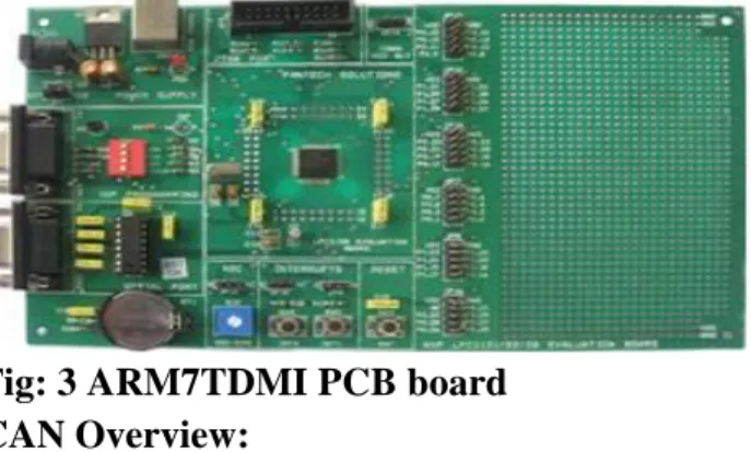
Fig: 3 ARM7TDMI PCB board
CAN Overview:
the affiliation of the management systems via a serial bus system. This bus had to meet some special necessities thanks to its usage in a very vehicle. With the employment of will, point-to-point wiring is replaced by one serial bus connecting all management systems. this can be accomplished by adding some CAN-specific hardware to every management unit that gives the "rules" or the protocol for transmittal and receiving data via the bus.
CAN or Controller space Network is a sophisticated serial bus system that with efficiency supports distributed management systems. it had been at the start developed for the utilization in motorized vehicles by Henry Martyn Robert old master GmbH, Germany, within the late Eighties, additionally holding the will license. will is internationally standardized by the International Standardization Organization (ISO) and therefore the Society of Automotive Engineers (SAE). The will protocol uses the information Link Layer and therefore the Physical Layer within the ISO - OSI model. There also are variety of upper level protocols on the market for will.
will is most generally utilized in the automotive and industrial market segments. Typical applications for will square measure motorized vehicles, utility vehicles, and industrial automation. alternative applications for will square measure trains, medical instrumentality, building automation, menage appliances, and workplace automation. attributable to the high volume production within the automotive and industrial markets, low price protocol devices square measure on the market.
There square measure regarding twenty million will nodes in use worldwide. By the year 2000 the amount of nodes is calculable to be a hundred and forty million. samples of vehicle bus systems, apart from will, square measure A-BUS from Volkswagen, VAN or Vehicle space Network, from Peugeot and Renault, and J1850 from Chrysler, General Motors and Ford. will is clearly the leading vehicle bus protocol in Europe. will could be a multi-master bus with AN open, linear structure with one logic transit line and equal nodes. the amount of nodes isn't restricted by the protocol. within the will protocol, the bus nodes don't have a selected address. Instead, the address data is contained within the identifiers of the transmitted messages, indicating the message content and therefore the priority of the message.
the amount of nodes could also be modified dynamically while not heavy the communication of the opposite nodes. Multicasting and Broadcasting is supported by will. will provides refined error-detection and error handling mechanisms like CRC check, and high immunity against magnetic attraction interference. inaccurate messages square measure mechanically retransmitted. Temporary errors square measure recovered. Permanent errors square measure followed by automatic switch-off of defective nodes. There’s bonded system-wide knowledge consistency.
The will protocol uses Non-Return-to-Zero or NRZ bit writing. For synchronization functions, Bit Stuffing is employed. There is a high information transfer rate of a thousand kilobits per second at a most bus length of forty meters or a hundred thirty feet once employing a twisted wire combine that is that the most typical bus medium used for will. Message length is brief with a most of eight information bytes per message and there's a coffee latency between transmission request and begin of transmission.
The bus access is handled via the advanced serial protocol Carrier Sense Multiple Access/Collision Detection with Non-Destructive Arbitration. This implies that collision of messages is avoided by bitwise arbitration while not loss of your time. There area unit 2 bus states, referred to as "dominant" and "recessive". The bus logic uses a "Wired-AND" mechanism, that is, "dominant bits" (equivalent to the logic level "Zero") write the "recessive" bits (equivalent to the logic level "One" ) as long as all nodes transmit recessive bits (ones), the Bus is within the recessive state.
As shortly mutually node transmits a dominant bit (zero), the bus is within the dominant state The will protocol handles bus accesses in keeping with the
thought referred to as “Carrier Sense Multiple Access with Arbitration on Message Priority”. This arbitration thought
International Journal of Science Engineering and Advance Technology, IJSEAT, Vol 2, Issue
8, August - 2014 ISSN 2321-6905
bitwise arbitration. every node sends the bits of its message symbol and monitors the bus level.
At a definite time nodes A and C send a dominant symbol bit. Node B sends a recessive symbol bit however reads back a dominant one. Node B loses bus arbitration and switches to receive mode. Some bits later node C loses arbitration against node A. this implies that the message symbol of node A includes a lower binary price and so the next priority than the messages of nodes B and C. during this approach, the bus node with the best priority message wins arbitration while not losing time by having to repeat the message.
Nodes B and C mechanically try and repeat their transmission once the bus returns to the idle state. Node B loses against node C, that the message of node C
is transmitted next, followed by node B’s message. it's not
permissible for various nodes to send messages with a similar symbol as arbitration may fail resulting in
collisions and errors. •As shortly mutually node transmits a dominant bit (zero), the bus is within the dominant state.
•The will protocol handles bus accesses in keeping with the thought referred to as “Carrier Sense Multiple Access with Arbitration on Message Priority”. This arbitration
thought avoids collisions of messages whose transmission was started by over one node at the same time and makes certain the foremost vital message is shipped initial while not time loss.
within the image on top of you see the trace of the transmit pins of 3 bus nodes referred to as A, B and C, and therefore the ensuing bus state in keeping with the wired-AND principle. If 2 or additional bus nodes begin their transmission at a similar time once having found the bus to be idle, collision of the messages is avoided by bitwise arbitration. Every node sends the bits of its message symbol and monitors the bus level.
LM35:
The LM35 series area unit exactness integrated-circuit temperature sensors, whose output voltage is linearly proportional to the stargazer (Centigrade) temperature. The LM35 therefore has a bonus over linear temperature sensors label in ° Kelvin, because the user isn't needed to cipher an oversized constant voltage from its output to get convenient Centigrade scaling. The LM35 doesn't need any external activity or trimming to supply typical accuracies of ±1⁄4°C at temperature and ±3⁄4°C
over a full−55 to +150°C temperature vary. Low price is
assured by trimming and activity at the wafer level. The
LM35’s low output ohmic resistance, linear output, and precise inherent activity build interfacing to readout or management electronic equipment particularly simple. It may be used with single power provides, or with and minus provides. Because it attracts solely sixty μA from its
provide, it's terribly low self-heating, but zero.1°C in still air. The LM35 is rated to work over a −55° to +150°C
temperature vary, whereas the LM35C is rated for a−40°
to +110°C vary (−10° with improved accuracy). The
LM35 series is offered prepackaged in tight TO-46 semiconductor device packages, whereas the LM35C, LM35CA, and LM35D are out there within the plastic TO-92 semiconductor device package. The LM35D is additionally out there in associate 8-lead surface mount tiny define package and a plastic TO-220 package.
Features
Calibrated directly in ° Celsius (Centigrade)
Linear + 10.0 mV/°C scale factor
0.5°C accuracy guarantee able (at +25°C)
Rated for full−55° to +150°C range Suitable for remote applications
Low cost due to wafer-level trimming
Operates from 4 to 30 volts
Less than 60 μA current drain Low self-heating, 0.08°C in still air
Nonlinearity only ±1⁄4°C typical
Low impedance output, 0.1for 1 mA load
DRIVER UNIT
:A relay is an electrically operated switch. Current flowing through the coil of the relay creates a magnetic field which attracts a lever and changes the switch contacts. The coil current can be on or off so relays have two switch positions and they are double throw (changeover) switches.
connection inside the relay between the two circuits; the link is magnetic and mechanical.
Relays are very simple devices. There are four major parts in every realy. They are
Electromagnet
Armature that can be attracted by the electromagnet
Spring
Set of electrical contacts
8.1 WORKING
When a current flows through the coil, the resulting magnetic field attracts an armature that is mechanically linked to a moving contact. The movement either makes or breaks a connection with a fixed contact. When the current to the coil is switched off, the armature is returned by a force approximately half as strong as the magnetic force to its relaxed position. Usually this is a spring, but gravity is also used commonly in industrial motor starters. Most relays are manufactured to operate quickly. In a low voltage application, this is to reduce noise. In a high voltage or high current application, this is to reduce arcing.
Fig 8.1 Circuit symbol of a relay
The relay's switch connections are usually labeled COM, NC and NO:
COM = Common, always connect to this, it is the moving part of the switch.
NC = Normally Closed, COM is connected to this when the relay coil is off.
NO = Normally Open, COM is connected to this when the relay coil is on.
LCD DISPLAY
Liquid crystal displays (LCDs) have materials which combine the properties of both liquids and crystals. Rather than having a melting point, they have a temperature range within which the molecules are almost as mobile as they would be in a liquid, but are grouped together in an ordered form similar to a crystal. An LCD consists of two glass panels, with the liquid crystal material sand witched in between them. The inner surface of the glass plates are
coated with transparent electrodes which define the character, symbols or patterns to be displayed polymeric layers are present in between the electrodes and the liquid crystal, which makes the liquid crystal molecules to maintain a defined orientation angle. One eachpolarizer’s
are pasted outside the two glass panels. Thesepolarizer’s
would rotate the light rays passing through them to a definite angle, in a particular direction. When the LCD is in the off state, light rays are rotated by the twopolarizer’s
and the liquid crystal, such that the light rays come out of the LCD without any orientation, and hence the LCD appears transparent. When sufficient voltage is applied to the electrodes, the liquid crystal molecules would be aligned in a specific direction. The light rays passing through the LCD would be rotated by the polarizer’s, which would result in activating / highlighting the desired
characters. The LCD’s are lightweight with only a few millimeters thickness. Since the LCD’s consume less
power, they are compatible with low power electronic circuits, and can be powered for long durations.
CONCLUSION
This project is implemented in two sections. First one known runs with ARM as master node and another as normal ARM data acquisition node to which sensors are connected. Communications between two nodes are accomplished through High Speed CAN communication. Sensors connected are temperature, ct and pt , and levle sensors. The master node collects all these information through CAN network and stores in three sessions. To acquire the results, respective session switches are provided at the master node. These results can be monitored on display.
References:
[1] Karl Henrik Johansson, Martin Törngren, and Lars
Nielsen,“Vehicle Application of Controller Area Network”.proc ofThe Handbook of Networked and Embedded Control SystemsControl Engineering, 2005, VI, pp.741-76
connection inside the relay between the two circuits; the link is magnetic and mechanical.
Relays are very simple devices. There are four major parts in every realy. They are
Electromagnet
Armature that can be attracted by the electromagnet
Spring
Set of electrical contacts
8.1 WORKING
When a current flows through the coil, the resulting magnetic field attracts an armature that is mechanically linked to a moving contact. The movement either makes or breaks a connection with a fixed contact. When the current to the coil is switched off, the armature is returned by a force approximately half as strong as the magnetic force to its relaxed position. Usually this is a spring, but gravity is also used commonly in industrial motor starters. Most relays are manufactured to operate quickly. In a low voltage application, this is to reduce noise. In a high voltage or high current application, this is to reduce arcing.
Fig 8.1 Circuit symbol of a relay
The relay's switch connections are usually labeled COM, NC and NO:
COM = Common, always connect to this, it is the moving part of the switch.
NC = Normally Closed, COM is connected to this when the relay coil is off.
NO = Normally Open, COM is connected to this when the relay coil is on.
LCD DISPLAY
Liquid crystal displays (LCDs) have materials which combine the properties of both liquids and crystals. Rather than having a melting point, they have a temperature range within which the molecules are almost as mobile as they would be in a liquid, but are grouped together in an ordered form similar to a crystal. An LCD consists of two glass panels, with the liquid crystal material sand witched in between them. The inner surface of the glass plates are
coated with transparent electrodes which define the character, symbols or patterns to be displayed polymeric layers are present in between the electrodes and the liquid crystal, which makes the liquid crystal molecules to maintain a defined orientation angle. One eachpolarizer’s
are pasted outside the two glass panels. Thesepolarizer’s
would rotate the light rays passing through them to a definite angle, in a particular direction. When the LCD is in the off state, light rays are rotated by the twopolarizer’s
and the liquid crystal, such that the light rays come out of the LCD without any orientation, and hence the LCD appears transparent. When sufficient voltage is applied to the electrodes, the liquid crystal molecules would be aligned in a specific direction. The light rays passing through the LCD would be rotated by the polarizer’s, which would result in activating / highlighting the desired
characters. The LCD’s are lightweight with only a few millimeters thickness. Since the LCD’s consume less
power, they are compatible with low power electronic circuits, and can be powered for long durations.
CONCLUSION
This project is implemented in two sections. First one known runs with ARM as master node and another as normal ARM data acquisition node to which sensors are connected. Communications between two nodes are accomplished through High Speed CAN communication. Sensors connected are temperature, ct and pt , and levle sensors. The master node collects all these information through CAN network and stores in three sessions. To acquire the results, respective session switches are provided at the master node. These results can be monitored on display.
References:
[1] Karl Henrik Johansson, Martin Törngren, and Lars
International Journal of Science Engineering and Advance Technology, IJSEAT, Vol 2, Issue
8, August - 2014 ISSN 2321-6905
[2] Renjun Li, Chu Liu and Feng Luo, “A Design for AutomotiveCAN Bus Monitoring System”, IEEE Vehicle
Power and Propulsion Conference (VPPC), September 3-5, 2008, Harbin,China
[3] CAN specification version 2.0. Robert Bosch GmbH, Stuttgart,Germany, 1991.
[4] Wilfried Voss, “A Comprehensible Guide to J1939”,
Published by
Copperhill Technologies Corporation
[5] Steve Corrigan, “Introduction to the Controller Area
Network”,Published by Texas Instruments Application
Report,SLOA101A,August 2002–Revised July 2008 [6] O. González, M. Rodríguez, A. Ayala, J. Hernández and S. Rodríguez, “Application of PICs and
microcontrollers in the measurement and control of parameters in industry”, Proc of theInternational Journal of
Electrical Engineering Education 41/3,pp.265-274, Feb 2001
[7] Microchip Technology Inc. DS41159E: PIC18FXX8
Data SheetPat Richards, “A CAN physical layer discussion”, MicrochipTechnology Inc. DS00228A
[8] Dogan Ibrahim, “Microcontroller based temperature
monitoring and control”, ISBN: 0750655569, Elsevier
Science & Technology Books
[9] P.M. Knoll and B.B. Kosmowski, “Liquid crystal
display unit forreconfigurable instrument for automotive
applications”, Opto-Electronics Review, 10(1), 75 (2002) [10] MCP 2551 High speed CAN Transceiver Datasheet.
[11] National Semiconductor, “LM35 Precision