Uplink Channel Allocation Scheme and QoS
Management Mechanism for Cognitive
Cellular-Femtocell Networks
Kien Duc Nguyen
1, Hoang Nam Nguyen
1, Hiroaki Morino
2and Iwao Sasase
31University of Engineering and Technology, Vietnam National University Hanoi, Vietnam 2
Shibaura Institute of Technology, Japan
3
Keio University, Japan,
[email protected], [email protected], [email protected], [email protected]
Abstract: Cognitive radio and femtocell are promising
technologies which can satisfy the requirements of future mobile communications in terms of dynamic spectrum sharing and high user density areas. Providing quality-of-service (QoS) guaranteed realtime services is challenging issue of future cognitive cellular-femtocell mobile networks. In this paper, we introduce a user’s QoS management mechanism used to protect SINR of macro users from QoS violation caused by femtocell users. We design a novel uplink channel allocation scheme (denoted as “flexible scheme”) for real-time connections. The scheme uses the information of interference level and channel occupancy collected at cognitive femtocell access points and their covering macro base station (MBS) and apply relevant selection criteria to select an appropriate channel which causes the minimums interference to macro users of the covering MBS. Performance results prove that comparing with femtocell-access-point (FAP)-based and MBS-based uplink channel allocation schemes, the novel “flexible scheme” can provide lower unsuccessful probability of new connection requests.
Keywords: Cognitive radio, femtocell, channel allocation,
interference management, QoS management, flexible scheme.
1.
Introduction
Recently, 4th generation (4G) mobile communications has been standardized in which the 4G mobile communications is able to provide high transmission rate up to 1 Gbps in the downlink and hundreds Mbps in the uplink [1]. A question arises that what the beyond 4G mobile communications (i.e. 4.5G, 5G) will offer to mobile customers. Considering the huge number of mobile customers, deployment scenarios (indoor, outdoor, urban, suburban etc.) and applications (voice, video, Internet services). It can be foreseen that future mobile communications demands high capacity, intelligent coverage and efficient resource utilization [2] which will be supported by deploying cognitive communications architecture [1].
Despite the high cost of deploying and operating a large number of small cells, femtocell has been proposed as a high efficient solution to increase indoor coverage and capacity [3, 4]. At the beginning, femtocell is considered as a low-power, short-range access point for indoor environment [4]. Recently, the deployment of femtocell is expanded to outdoor environment where femtocells are used as traditional pico cells [3]. In the deployment, femtocells can be deployed by mobile operators in residential, enterprise and open areas.
They will form a so-called femto subsystem in which interference management becomes an important task [3, 4]. Cognitive cellular-femtocell systems were proposed recently in which macro base stations and cognitive femtocell access points (CFAP) are considered as primary and secondary systems, respectively. CFAPs are assumed to have cognitive functionalities which are able to sense the available spectrum and opportunistically consume it for data transmission [4]. For radio resource management in cognitive cellular-femtocell networks, recent published papers found in the literature have only focused to solve the problems of opportunistic channel allocation [4, 5] for data (non realtime services). Although the demand of providing real-time services in femtocells is an important issue in future cognitive cellular-femtocell mobile networks, there is no detailed discussion and proposal of channel allocation for real-time connections and QoS management mechanism of both macro users (MUs) and femtocell users (FUs) when providing real-time services.
Performance of three channel allocation strategies are evaluated including “FAP-based cognitive channel allocation” proposed by [5], “MBS-based cognitive channel allocation” presented in [7] and the proposed flexible cognitive channel allocation. We also present a QoS management mechanism and a channel verification procedure which are used in order to eliminate the problems of QoS violation in cognitive cellular-femtocell networks. The paper is organized as follows: the system model and concepts of physical layer QoS management are described and discussed in the next section. QoS management mechanism and channel verification procedure are presented in Section 3. The next section describes selected channel allocation schemes including the novel scheme. Simulation model and parameters including standardized path loss models are described in section 5. Performance comparison is presented and discussed in section 6. Finally, the conclusion remarks are given in the last section.
2.
System model
Femtocell was first proposed for covering small indoor areas. Recently, the deployment of femtocell is also proposed for outdoor coverage in particular scenarios such as in public areas, in high density user locations e.g. airports, parks [3]. In current femtocell architecture, femtocells operate at frequencies which are randomly selected.
Internet
Femto Gateways Open Access Femto Zone
Mobile Core Network (CS, PS, IMS)
Closed Access Femto Zone
Cognitive Femto Access Point
(CFAP)
Mobile RAN Management System
Femto Management
System
Macro base station (MBS)
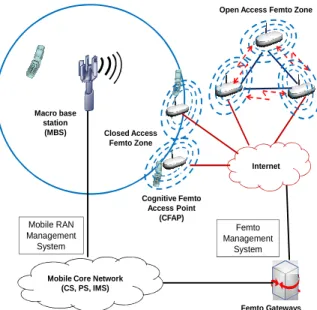
Figure 1. Cognitive cellular-femtocell network model for
beyond 4G mobile communications
Fig. 1 shows a two-tier cognitive cellular-femtocell network model which we consider as a candidate for beyond 4G mobile communications. In the cellular domain, we do not aim to focus on any specific air interface technologies because the model is used as a general system model only. In this model, a CFAP can form a closed access femto zone in which only authorized/registered users can access to the CFAP. In this scenario CFAP operates equivalently as a private indoor access point like a Wi-Fi device. One or a number of CFAP can form an open access femto zone which accepts access requests made by authenticated users. This scenario is applied in public locations e.g. shopping centers,
airports, railway stations. Deploying CFAPs with small coverage size aims to not only increase the signal quality of mobile users but also reduce the cross-tier interference because the transmission power of mobile users is decreased. In the scope of this paper, we investigate the methods in which CFAPs perform uplink channel allocation to new real-time call requests of FUs in the scenario of fixed users. Assume that MBSs and CFAPs use the same frequency range in which MBSs operate as the primary system. Both of MBSs and CFAPs have cognitive functionalities including spectrum sensing or channel quality sensing. Cognitive radio recently is considered effective for opportunistic access [8] in which channels are allocated to secondary users in a certain short period. However, real-time communications have strict QoS requirements and normally, the channel allocated to a real-time connection has to be available in a long period. That rises to the need of how to allocate stable spectrum/channel to real-time connections. In the network model, we assume that a MBS will be able to interact with CFAPs which are located in the coverage area of the MBS in order to exchange the current information of spectrum utilization of the covering MBS. By using cognitive functionalities and interacting with their covering MBS, CFAP monitors the interference level of all channels in order to select the most appropriate channel which is satisfying the QoS of FUs while not violating QoS of MUs.
We assume that Femto Management System (FMS) and Mobile RAN Management System (MRMS) are two control entities. Control messages and information exchanged between these entities are transmitted via the core network of cellular domain and the Internet so that they will not consume the limited wireless radio resource. The interaction between these two entities is for supporting mobility management and radio resource management by exchanging important information such as the channel usage condition of MBSs or CFAPs. When we consider the case that a user moves between femto zones or between a femto zone to MBS’s zone, the user needs the supports of location update and connection handover. FMS and MRMS have to be able to support handover procedures such as handover decision, cell selection and resource allocation. The FMS and MRMS also should be coordinated in radio resource management. When a CFAP receives a new real-time call request from a FU, it has to allocate radio resource (channel) to the FU. As MUs are considered as primary users whose QoS must be guaranteed [9], the CFAP has to select the channel which causes minimum effects to the MUs of the covering MBS [3, 4].
connection, the signal quality of mobile user must have a certain signal-to-interference and noise ratio (SINR) level. The SINR level of each application type (voice, video, and data) is considered as the physical layer QoS (from now on denoted for short as QoS). SINR of a mobile user measured at MBSs or CFAPS is used as uplink QoS. Clearly, when a CFAP receives a new call request from a FU, it should select a channel which satisfies FU’s SINR while not causing strong interference to other MUs using same channel. In the next section, we will introduce a QoS management mechanism and its channel verification procedure.
3.
QoS management mechanism
FU CFAP FMS MRMS MBSs
Channel allocation Call Request
QoS Verification Request
QoS Verification
Request QoS Control Inquiry
QoS Control Reply
QoS Verification Reply QoS Verification
Reply Connection verification Waiting for the
verification reply Waiting for a time out
period Call Reply
Figure 2. QoS management mechanism: channel
verification procedure
Admission control including the channel allocation procedure and QoS management mechanism are illustrated in Fig. 2. In the figure, control message exchanges are shown as black lines, while control processes are shown in rectangle blocks. When a new call request of a FU arrives to a CFAP, the CFAP first performs a channel allocation scheme to allocate a channel to the FU. In order to guarantee that QoS of ongoing connections of MUs is not violated, a QoS management mechanism including a channel verification procedure is applied. The CFAP performs the channel verification procedure to check if the QoS of a MU, which is consuming the same channel is violated. The new call request is considered unsuccessful in two cases: either there is not available channel or the allocated channel causes QoS violation to a MU.
After allocating a channel k to a new call request, CFAP sends a verification request to the FMS to verify if the QoSs of other MUs using the channel k are violated. The FMS forwards the verification request to the MRMS and waits for a time out period. The MRMS sends QoS control inquiry to MBSs, which are the covering MBS of the CFAP and neighbors of the covering MBS. If a MU using channel k has QoS violation, the MBS covering of this MU will send QoS control reply to MRMS. The MRMS forwards the QoS control reply to the FMS. Then the FMS sends the QoS verification reply to the CFAP and terminates the time out period. While the CFAP is waiting for the verification reply,
the FU is temporarily connected with the CFAP and transmits probe signals. In the case of there is not QoS violation at MUs, the CFAP permanently accepts the FU and allocates the channel k to the FU. Otherwise, the CFAP will terminate the connection and also consider that the realtime call request is unsuccessful.
In the next section, we will describe three channel allocation schemes: FAP-based cognitive channel allocation scheme [5], MBS-based cognitive channel allocation scheme and the proposed flexible channel allocation scheme which allocates channels to new realtime call requests according to interference data measured at both CFAPs and MBSs.
4.
Channel allocation schemes
Channel allocation schemes operate as described below under following assumptions. Assume that the cognitive cellular-femtocell network uses a pool of C orthogonal channels for real-time connections. In a MBS or a CFAP, at any given time, a channel is allocated to only one ongoing MU or one ongoing FU, respectively. MUs are primary users for which a certain physical layer QoS is guaranteed (as mentioned above, we consider the QoS parameter is the required SINR). When a CFAP allocates a channel to a FU, it first has to provide the required QoS of the FU. However, the FU must not cause the QoS degradation of the MUs which are using the same channel. Assume that updating the uplink interference level of MBSs and the QoS of MUs is performed by the interaction/information exchange of MRMS and FMS. Moreover the channel allocation schemes in CFAP are performed after updating information from covering MBS. If the QoS of a MU is violated because a new FU has been accepted to the network, the covering CFAP of the FU will be informed and then it can either try to allocate another channel to this FU or to block the FU‘s connection request. Operational procedures of three selected channel allocation schemes are as follows.
4.1 FAP-based cognitive channel allocation scheme [5]
In the FAP-based cognitive channel allocation scheme (denoted as CFAP-based scheme), each CFAP will measure the interference level of all available channels which are not allocated to ongoing FUs of the CFAP. When a CFAP j receives a connection request from an FU, it will select the channel k which satisfies two criteria: 1) it is unused by any FUs of the CFAP and 2) it has the minimum interference level, as described in Equation (1) below.
k
=arg
min
(
cj)
c
I
,1 ≤ c ≤ C (1)where Icj is the total interference level of channel c is measured at the CFAP j. The interference level of all channels measured at the CFAP j is updated periodically. After being assigned a channel k, the FU transmits a probe signal using an initial transmission power Pi. Its SINR is measured by this equation: SINR =
noise Ik
j k j +
where
Pr
kj is the power received from the user at CFAP j. If the SINR of the probe signal by FU measured at the CFAP does not satisfy the FU’s QoS, the CFAP asks the FU to perform a power control process. The power control will complete either when the FU’s QoS is satisfied or the maximum transmission power of the FU is assigned. In the case of the FU’s QoS is still not satisfied after completing the power control process, the CFAP will release the allocated channel k and consider that the call request is not successful or unsuccessful. Otherwise, the CFAP allocates the channel to the FU and then performs the channel verification procedure as illustrated in Fig. 2.4.2 MBS-based cognitive channel allocation scheme [7]
When using the MBS-based cognitive channel allocation scheme (denoted as MBS-based scheme), the cognitive cellular-femtocell network needs more frequent information exchange between the MRMS and FMS. A CFAP periodically updates interference data of all channels measured at its covering MBS. A MBS periodically sends a broadcast packet to all CFAPs locating in its coverage. This packet can be sent from the MBS to CFAPs via a broadcasting channel or through the communications between MRMS and FMS. The packet contains interference information of all channels measured at the MBS.
When the CFAP receives a connection request of a FU, it will select the channel k* which satisfies two criteria: 1) it is unused by other ongoing FUs of the CFAP and 2) it has the minimum interference level IkM* measured at the covering MBS M of the CFAP, as described in Eq. (3) below.
*
k
=arg
min
(
Mc)
c
I
,1 ≤ c ≤ C (3)where IcM is the total interference level of channel c which is measured at the covering MBS M of the CFAP. Selecting a channel according to Eq. (3) leads to minimize uplink interference to the covering MBS of the CFAP. The channel verification procedure is then performed similarly.
4.3 “Flexible scheme” of cognitive channel allocation
When performing simulation experiments, we realized that the CFAP-based scheme will locally assign a channel k which causes minimum interference to CFAPs i.e. less effects to the QoS of surrounding FUs. The MBS-based scheme will produce a channel k* which causes minimum effect to MU’s QoS [7]. Because femtocell has small coverage radius, channels allocated to FUs often satisfy FUs’s QoS. From these observations, we propose a more effective channel allocation scheme. We denote it as “flexible scheme” which works as follows. Beside updating interference information of all channels to all CFAPs as described in MBS-based scheme, the covering MBS also send its CFAPs the list of channels being occupied by MUs at the MBS.
According to the updated data, a CFAP divides the channel
pool into two sets C1 and C2 in which C= C1+C2. C1 is the set of the channels not being used by MUs in the covering MBS, and C2 is the set of the channels being used by MUs in the covering MBS.
When the CFAP j receives a new connection request of a FU, the “flexible scheme” operation is described in two steps as follows:
Step 1: If the set C1 is empty, go to Step 2. Otherwise, the CFAP j selects the channel C* which satisfies three criteria: 1) it belongs to the channel set C1 (not being used by the covering MBS), 2) it is not used by other FUs of the CFAP j, and 3) it has the minimum total interference level ICj*measured at the CFAP j, as shown in Eq. (4) below.
C* =
arg
min
(
c)
j cI
, 1 ≤ c ≤ C1 (4)where Icj is the total interference level of channel c is measured at the CFAP j. After that, the channel verification procedure introduced in Fig. 2 is performed similarly. If there is a MU of cellular domain (might belong to other neighbor MBSs) which has QoS violation, the CFAP j will perform the one more attempt of channel allocation by using Step 2 below.
Step 2: The CFAP j will select the channel C** which satisfies three criteria: 1) it belongs to the channel set C2, 2) it is not being used by other FUs of the CFAP j and 3) it has the minimum total interference level ICM**measured at its covering MBS M. Such that:
C** =
arg
min
(
Mc)
cI
, 1 ≤ c ≤ C2 (5)where IcM is the total interference level of channel c measured at the covering MBS M. The channel verification procedure is then performed similarly. The new call request is considered unsuccessful if the channel C** does not pass the channel verification.
In the next sections, we will present the simulation model used for evaluating and performance comparison of above channel allocations schemes. The performance metric is “unsuccessful probability” defined below:
Unsuccessful probability =
quest Total
quest ul
Unsuccessf Of
Number
Re _
Re _ _
_
(6)
5.
Simulation model
Figure 3. Layout of simulation model
For more details, the simulation model includes MBSs that each MBS provides the cell coverage radius of 500m with the antenna height of 30m. In each macrocell (MBS), a number of CFAPs (depending on simulation scenarios) is uniformly distributed. MUs and FUs are also uniformly distributed in each macrocell and each CFAP, respectively. A MBS allocates channels to its MUs randomly. In the paper, we only consider stationary MUs and FUs with its antenna the height between 1m and 3m, respectively. The femtocell coverage radius is 15m and CFAP has antenna height between 1m to 5m. In all simulation scenarios, MBSs and CFAPs manage the same number of uplink channels NC = 100. Assume that only one uplink channel is allocated for a MU at whole simulation time. The transmission power range of MUs is between 1mW and 125mW [10] whereas the transmission power of FUs is fixed at 1mW. Additionally, the uplink transmission power of MUs is controlled by a power control process with the SINR target of 3 dB [5]. The FU’s uplink QoS requirement (SINR) is set to 5dB. The uplink traffic load in each CFAP is set according to selected simulation scenarios.
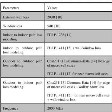
Consider CFAPs and FUs are indoor devices whereas MBSs and MUs are outdoor devices. Standardized path loss models used for calculating SINR in femtocell networks [10, 15] are given in Table 1. The signal transmitted between a base station and users can be classified into four cases: indoor to indoor, indoor to outdoor, outdoor to outdoor and outdoor to indoor links.
Cost231-Okumura-Hata is well-accepted by the mobile cellular community. The expression of Cost231 for built-up areas is as follows:
L(dB) = 46.3 + 33.9log10(f) – 13.82log10(hb) + (44.9 - 6.55log10(hb)) × log10(d) – F(hm) + C , (7)
With C = 0 dB for small to medium-size cities.
F(hm) = (1.1log10(f) – 0.7) ×hm – (1.56log10(f) – 0.8) , (8) where f is the carrier frequency [MHz]; hb is the base station height above ground level [m]; hm is the mobile station height above ground level [m]; d is the distance from the base station [km].
ITU P.1411 was designed for the planning of short range outdoor systems. P1411 line-of-sight street canyon method is recommended which applies to situations where the two terminals are in LOS but are surrounded by buildings. In this
paper, we used the lower bound for the path loss using the following expressions:
Lbp + 20log10 (d/Rbp) for d ≤ Rbp L(dB) = (9) Lbp + 40log10 (d/Rbp) for d > Rbp ,
where the breakpoint distance is given by Rbp = 4hbhm/λ and the basic transmission loss at the breakpoint distance is given by:
Lbp(dB) = | 20log10(λ2/(8πhbhm)) | , (10)
with λ is the wavelength (m); hm and hb are the base station and the mobile unit’s height above street level respectively (m); d is the distance from base station (m).
ITU P.1238 predicts path loss between two indoor terminals assuming an aggregate loss though furniture, internal walls and doors. The expression for the path loss is given by:
L(dB) = 20log10(f) + Nlog10(d) + Lf(n) – 28 , (11) where N is the distance power loss coefficient; f is the carrier frequency [MHz]; d is the separation distance (m) between the base station and portable terminal (where d > 1m); Lf is floor penetration loss factor (dB); n is number of floors between base station and portable terminal (n ≥ 1). In our simulation, we used N = 28, Lf(n) = 4n and n = 1 for residential factor.
Table 1. ITU path loss models
Parameters Values
External wall loss 20dB [10]
Window loss 5dB [10]
Indoor to indoor path loss modeling
ITU P.1238 [11]
Indoor to outdoor path loss modeling
ITU P.1411 [12] + wall/window loss
Outdoor to outdoor path loss modeling
Cost231 [13]-Okumura-Hata [14] for edge of macro cell cases
ITU P.1411 [12] for near macro cell cases
Outdoor to indoor path loss modeling
Cost231[13]-Okumura-Hata [14] for edge of macro cell cases + wall/window loss
ITU P.1411 [12] for near macro cell cases + wall/window loss
Frequency 2000 MHz
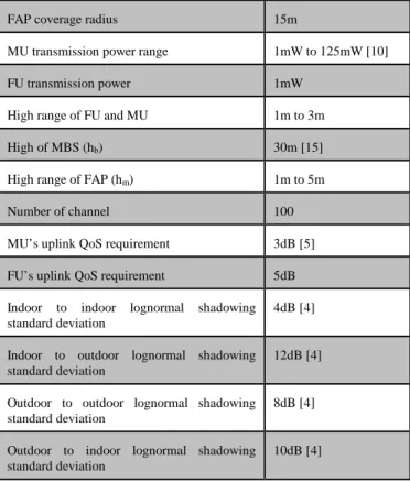
The common simulation parameters are summarized in Table 2 given below.
Table 2. Common simulation parameters
Simulation parameters Values
Cell layout 7 cell model
MBS sensitivity -121dBm [10]
FAP sensitivity -116dBm [10]
FAP coverage radius 15m
MU transmission power range 1mW to 125mW [10]
FU transmission power 1mW
High range of FU and MU 1m to 3m
High of MBS (hb) 30m [15]
High range of FAP (hm) 1m to 5m
Number of channel 100
MU’s uplink QoS requirement 3dB [5]
FU’s uplink QoS requirement 5dB
Indoor to indoor lognormal shadowing standard deviation
4dB [4]
Indoor to outdoor lognormal shadowing standard deviation
12dB [4]
Outdoor to outdoor lognormal shadowing standard deviation
8dB [4]
Outdoor to indoor lognormal shadowing standard deviation
10dB [4]
6.
Performance comparison
Following simulation scenarios are carried out in which we compare the unsuccessful probability of channel allocation schemes under different system configuration.
Scenario 1: The number of CFAPs in each MBS (CFAPs/MBS) is 10. The maximum number of simultaneous active FUs on each CFAP is 10 or the uplink load of CFAPs is 10% of total NC channels).
Scenario 2: The number of CFAPs/MBS is increased to 20. The uplink load of CFAPs is 10%.
Scenario 3: The number of CFAPs/MBS is 10. The uplink load of CFAPs is increased to 30%.
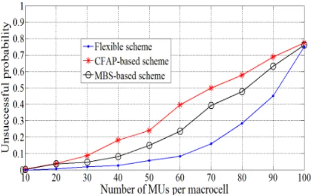
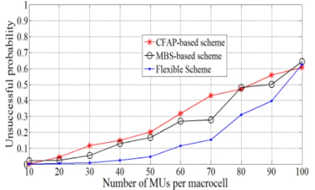
Figure 4. Unsuccessful probability versus number of MUs
per macrocell where 10 CFAPs/MBS and the uplink load of CFAP is 10%
In the first simulation scenario, the transmission power of MUs is controlled between 1mW and 125mW while the transmission power of FUs is fixed at 1mW. Each CFAP has the uplink traffic load of 10%. The number of MUs in each macro cell is varied between 10 and 100. The QoS of FUs is SINR = 5dB. The positions of CFAPs are uniformly distributed around MBS and in MBS’s coverage. As shown in Fig. 4, the flexible scheme can provide a much smaller
unsuccessful probability than that of the CFAP-based and MBS-based schemes. At the MBS’s load of 40 active simultaneous MUs in each MBS (MUs/MBS), the unsuccessful probability of the flexible scheme is less than
1% whereas that of the CFPA-based and MBS-based
schemes provide an impractical unsuccessful probability of around 10% and 7%, respectively. The flexible scheme shows better performance at higher MBS’s load and it can even provide low unsuccessful probability of realtime connection requests at medium MBS’s load (around 55 MUs/MBS). The reason is that when using the flexible scheme, the CFAP first selects the channel which has the local minimum interference level (at the CFAP) and is not used by ongoing MUs of covering MBS. Thus the CFAP can satisfy FU’s QoS and does not cause interference affecting to MU’s QoS. Otherwise, the CFAP selects a channel which can be currently used by the covering MBS but has minimum interference at the covering MBS. That means it can cause minimum effects to QoS of the MUs connected with the covering MBS. In this scenario, when the number of active MUs less than 30 (considered as a low MBS load), the performances of MBS-based and CFAP-based schemes are nearly identical whereas the flexible scheme provides very small unsuccessful probability.
Figure 5. Unsuccessful probability versus number of MUs
per macrocell where 20 CFAPs/MBS and the uplink load of CFAP is 10%
In the second simulation scenario, it aims to observe the unsuccessful probability of channel allocation schemes in the case of the number of CFAPs is increased to 20 i.e. higher femtocell density while keeping the similar uplink traffic load of 10% in each femtocell. The QoS of FUs is SINR =
5dB. The transmission power of FUs is set at the fixed value
is not possible to provide realtime connection requests in cognitive cellular-femtocell mobile networks.
Figure 6. Unsuccessful probability versus number of MUs
per macrocell where 10 CFAPs/MBS and the uplink load of CFAP is 30%
In the third simulation scenario, it aims to compare the unsuccessful probability of channel allocation schemes in the case of the uplink traffic load of each CFAP is 30% i.e. high capacity femtocell while keeping 10 CFAPs in each MBS. As shown in Fig. 6, the unsuccessful probability of all schemes increases as the uplink traffic load of each CFAP increases. The flexible scheme still provides a much better unsuccessful probability than the CFAP-based and MBS-based schemes. In this scenario, the flexible scheme can still keep the unsuccessful probability less than 5% when the MBS’s load reaches 50 simultaneous active MUs. This figure proves that when CFAP’s load of realtime services increases, it causes heavy interference to active MUs of the covering MBS. That means cognitive cellular-femtocell mobile networks should define a certain realtime service load of femtocells. It is an open and interesting research topic for future study.
Figure 7. Performance comparison in the case of the same
number of active FUs (300FUs) in a macrocell
The flexible scheme has shown better performance gain comparing with other schemes. Now we evaluate and compare the performance of the flexible scheme in the case of the total number of active FUs of both scenarios is identical (300 active FUs in a macrocell). Fig. 7 shows when the uplink load of a CFAP is high (30FUs/CFAP and
10CFAPs/MBS) i.e. CFAPs are high-capacity access points,
the flexible scheme is able to maintain unsuccessful probability of 10% when the offer load of the covering MU rises to 62% (62 active MUs/ MBS). In the scenario when the number of CFAPs is high and CFAPs are low-capacity access points (10FUs/CFAP and 30CFAPs/MBS), the
unsuccessful probability reaches 10% when the offer loads of the covering MU raises to 46% (46 active MUs/ MBS). From the collected performance data, it shows that in cognitive cellular-femtocell mobile networks, deploying high-capacity CFAPs is better than deploying low-capacity CFAPs. Clearly, at theoretical point of view, when reducing the number of CFAPs i.e. low CFAP density there will be fewer CFAPs locating nearby MBSs. Therefore MBSs will have lower uplink interference. This result is also used as the validation of our simulation tool.
Simulation results have statistically demonstrated the effectiveness of the flexible scheme. When analyzing the operation of three channel allocation schemes, we found that most of unsuccessful requests happened because ongoing MU of the covering MBS has QoS degradation. Following issues can verify the gains of the flexible scheme when comparing with CFAP-based and MBS-based schemes: - When using the CFAP-based scheme, a CFAP allocates to
a FU a channel which has the minimum interference measured at the CFAP. But at this time, the channel can have strong interference at the covering MBS. Thus the channel verification procedure performed later would not be satisfied. This results in high unsuccessful probability. - When using the MBS-based scheme, a CFAP will allocate
to a FU a channel (denoted as Channel-A) which has minimum interference measured at the covering MBS. A situation appears that the Channel-A might be consumed by a MU of the covering MBS while another channel (Channel-B), which has higher interference level measured at the CFAP but is free in the covering MBS. In the case of the CFAP is nearby the covering MBS, allocating Channel-B is a better solution because the Channel-B will not violate QoS of ongoing MU of the covering MBS. Also, as the CFAP is nearby the covering MBS i.e. it is far from other MBSs, the choice of Channel-B will cause less interference to other MBSs. When allocating the free Channel-B to the FU, this FU does not have interference from the MU of the covering MBS i.e. better FU’s SINR can be achieved.
In the last simulation experiment, the unsuccessful probability of channel allocation schemes is evaluated in the cases of CFAPs located nearby the MBS (approximately
50m around MBS). The simulation result shown in Fig. 8
demonstrates our above verification.
Figure 8. Unsuccessful probability versus number of MUs
per macrocell where CFAPs are located nearby the MBS (approximately 50m around MBS)
7.
Conclusions
In this paper, we have presented a feasible cognitive cellular-femtocell mobile network architecture where cognitive radio and femtocell deployment are two key aspects which are expected to fulfill important requirements of beyond 4G mobile communications in terms of coverage and spectrum utilization. We introduce a physical layer QoS management mechanism and proposed a novel uplink channel allocation scheme denoted as “flexible scheme” for new realtime connection requests. Performance results obtained by computer simulation show that the proposed flexible channel allocation scheme outperforms both CFAP-based and MBS-based schemes in terms of low unsuccessful probability. In order to achieve high system capacity and resource utilization in cognitive cellular-femtocell networks, the interaction of MRMS and FMS will play important role. It is suggested that deploying high-capacity CFAPs would bring better performance than deploying low-capacity CFAPs when providing realtime services. For future works, we would focus on solving technical problems appeared in the case of mobile MUs and FUs. In this case, high-performance mobility management will be the key for the success of cognitive cellular-femtocell mobile communications networks.
8.
Acknowledgment
This work has been supported by Vietnam National University Hanoi (VNU) under the research project QG.13.06.
References
[1] S. Patel, M. Chauhan, K. Kapadiya, “5G: Future Mobile Technology-Vision 2020”, International Journal of Computer Applications, Vol. 54, No. 17, pp. 6-10, Sept. 2012.
[2] S. Patil, V. Patil, P. Bhat, “A Review on 5G Technology”, International Journal of Engineering and InnovativeTechnology (IJEIT), Vol. 1, Issue. 1, pp. 26-30, January 2012.
[3] J. G. Andrews, H. Claussen, M. Dohler, S. Rangan, M. C. Reed, “Femtocells: Past, Present, and Future”, IEEE Journal on Selected Areas in Communications, Vol. 30, Issue. 3, pp. 497-508, April 2012.
[4] D. C. Oh, H. C. Lee and Y. H. Lee, “Cognitive Radio Based Femtocell Resource Allocation”, 2010 International Conference on Information and Communication Technology Convergence (ICTC2010), pp. 274-279, Nov. 2010.
[5] Y-y. Li and E. S. Sousa, “Cognitive uplink interference management in 4G cellular femtocells”, 21st Annual IEEE International Symposium on Personal, Indoor and Mobile Radio Communications, pp. 1567-1571, Sept. 2010.
[6] N. Meghanathan, “A Survey on the Communication Protocols and Security in Cognitive Radio Networks”, International Journal of Communication Networks and Information Security (IJCNIS), Vol. 5, No. 1, April 2013.
[7] K. D. Nguyen, H. N. Nguyen and H. Morino, “Performance Study of Channel Allocation Schemes for beyond 4G Cognitive Femtocell-Cellular Mobile Networks”, 2013 IEEE Eleventh International Symposium on Autonomous Decentralized Systems (ISADS), pp. 1-6, March 2013.
[8] S. Tang and Y. Xie, “Performance Analysis of Unreliable Sensing for an Opportunistic Spectrum Sharing System”, International Journal of Communication Networks and Information Security (IJCNIS), Vol. 3, No. 3, December 2011.
[9] D. T. Ngo, L. B. Le, T. L. Ngoc, E. Hossain, and D. I. Kim, “Distributed Interference Management in Femtocell Networks”, IEEE Vehicular Technology Conference (VTC Fall) 2011, pp. 1-5, Sept. 2011. [10]The femto forum, White Paper “Interference
Management in UMTS Femtocells”, December 2008. [11]International Telecommunication Union, “ITU‐R
Recommendations P.1238: Propagation data and prediction models for the planning of indoor radio communications systems and radio local area networks in the frequency range 900MHz to 100GHz”, Geneva, 1997.
[12]International Telecommunication Union, “ITU‐R Recommendations P.1411‐3: Propagation data and prediction methods for the planning of short range outdoor radio communication systems and radio local area networks in the frequency range 300 MHz to 100 GHz”, Geneva, 2005.
[13]Commission of the European Communities, “Digital Mobile Radio: COST 231 View on the Evolution Towards 3rd Generation Systems”, L‐2920, 1989. [14]Y. Okumura, E. Ohmori, T. Kawano and K. Fukuda,
“Field strength and its variability in VHF and UHF land mobile radio service”, Rev. Electr. Commun. Lab., Vol. 16, pp. 25‐73, 1968.