Products: R&S® SMU, R&S® SMJ, R&S® SMATE, R&S®SFU, R&S® FSP, R&S® FSQ, R&S® FSU, R&S®
FSL, R&S®FSUP, R&S® FSMR, R&S® ESU, R&S® ESCI, R&S® ESPI, R&S® UPV, R&S® ZVA, R&S® ZVB, R&S® ZVT,R&S® ZVL
Remote Operation of R&S Instruments
Using Remote Desktop Connection via LAN
Application Note
Rohde & Schwarz instruments can be shared when users wish to use the same instrument. This can be done quite easily with the LAN interface, which comes as a standard option. Through this interface, Rohde & Schwarz instruments can be connected directly to a network, and users with access to the network can manually operate the instrument from a remote computer. This Application Note lists all instruments that support these features and describes the steps necessary to set up and configure the
1 Overview ... 3
2 List of Instruments... 3
3 Basic Requirements... 3
PC Hardware Requirements... 3
PC Software Requirements ... 3
4. DHCP Networks... 4
5. Networks with Fixed IP Addresses ... 8
6. Point to Point Network ... 9
7. References... 10
8. Ordering Information ... 10
1
1
Overview
Rohde & Schwarz instruments allow a company to share its instruments when more than one user wishes to use the same instrument. They can be remote-controlled from a desk that is part of a test assembly located in another area in the same building. This can be easily done by operating the instrument like a conventional network device (e.g. network printers, fax machines, etc.) via the LAN interface. Together with the “Remote Desktop Connection” program included free of charge in Windows® OS, no additional hardware is required.
This Application Note describes how to connect and configure various kinds of networks (DHCP, Fixed IP address, Direct) and how to use the “Remote Desktop Connection” program to control Rohde & Schwarz instruments.
2
List of Instruments
The following Rohde & Schwarz instruments support the feature described in the Application Note:
Signal generation R&S SMU family, R&S SFU
Spectrum analysis R&S FSQ, R&S FSP, R&S FSL, R&S FSU, R&S FSMR, R&S FSUP, R&S ESU, R&S ESCI, R&S ESPI
Network analysis R&S ZVA, R&S ZVT, R&S ZVB, R&S ZVL
Audio analysis R&S UPV
3
Basic Requirements
PC Hardware Requirements
Minimum Recommended
Interface Ethernet card (LAN card) ---
PC Software Requirements
Minimum Recommended
OS Windows/ Me / XP® / 95 / 98 / NT 4.0 / 2000 VISTA WindowsMe / XP ® 98 / 2000 /
Program
s Remote Desktop Connection
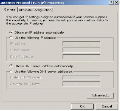
Under this protocol an IP address is assigned to the instrument automatically after it has been configured for DHCP network (see Fig. 4.1) and connected to the network. Simply enter the unique computer name or the IP address of the instrument into the Remote Desktop program and the instrument will be in remote operation. The following section describes step-by-step how this is done.
Access to Windows OS
In the following explanations, access to the Windows OS is required. Depending from the instrument type, it can be achieved in different ways:
Network Analyzers ZVA, ZVB, ZVT, ZVL: Press the Windows-hardkey at the frontpanel
á
,
or close the firmware via MENU > File > Exit (e.g. ZVL).Otherwise connect a keyboard and a mouse to the instrument before turning it on 1). Press the Windows key or CTRL-ESC to display the
Windows menu.
Instrument unique computer name
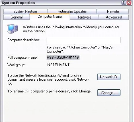
Switch to Windows OS: Start > Control Panel > System > Computer Name
In the Full computer name field, the instrument's unique computer name will appear, for example RSSMU200A101119 (see Fig. 4.2).
Fig. 4.1 Instrument TCP/IP protocol settings
Fig. 4.2 Display of the instrument’s unique computer name
Instrument IP address
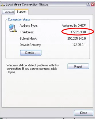
Find the network connection icon on the instruments toolbar and double-click it. Select the folder “Support” (see Fig. 4.3).
Alternatively, select Windows > Start > Control Panel > Network Connections > LAN or High-Speed Internet. Double-klick the interface in use (Ethernet 1 or Ethernet 2), the window with the Ethernet status willpop up. Select the Support tab and find the the IP address (see Fig. 4.3). The IP address can also be shown via the DOS mode 2). On the keyboard
press CRTL-ALT-DEL and select the TASK MANAGER command button. In the TASK MANAGER windows, select File > New Task and enter “CMD” to get into the DOS mode. Type in “ipconfig”; the IP address will be displayed as well. (see Fig. 4.4)
Fig. 4.3 IP address in Windows mode
Fig. 4.4 IP address in DOS mode
Start the Remote Desktop connection program on the PC
After verifying the IP address, select the Remote Desktop Connection (Fig. 4.5) program on the external PC. In Windows XP, you will find it under
Start > Programs > Accessories > Communications > Remote Desktop Connection.
Fig. 4.5 Remote Desktop Connection program
Before the instrument is in remote operation, the instrument ID and password have to be entered. (The instrument ID and password are both “instrument”.)
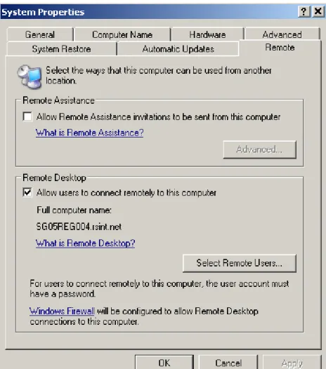
Before the connection to the instrument can be established, please take note of the following:
- The instrument should allow remote connection (see Fig. 4.6).
5.
Networks with Fixed IP Addresses
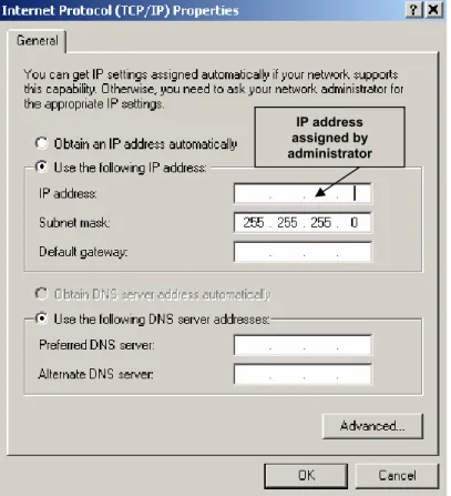
Normally, the network administrator will maintain and assign IP addresses. Enter the address in the TCP/IP settings of the instrument under Use the following IP address as shown in Fig. 4.7.
Fig. 4.7 TCP/IP settings
Connect the instrument to the network
Connect the instrument to the network via the LAN interface.
Enter the IP address
Open the TCP/IP properties setting in the instrument. Enable the Use the following IP address radio button and enter the IP address as received from your network administrator.
Start the Remote Desktop Connection program
Start the Remote Desktop program on the external PC; enter the instrument IP address and press Connect. Before the instrument is in remote operation, the instrument ID and password have to be entered. (The instrument ID and password are both “instrument”.)
IP address assigned by administrator
6.
Point to Point Network
This is a simple direct connection from the instrument to the PC via the LAN interface. A cross-over cable is required. If “AUTO-MDIX” functionality is supported, no cross-over cable is necessary.
Connect the cross-over cable from the LAN interface of the external PC to the instrument.
Assign an IP address to the instrument and the external PC.
The IP address of 192.168.xxx.yyy should be used. xxx and yyy can be any values from 1 to 254, the value of the subnet mask is 255.255.255.0 For example, set the IP address of the instrument as shown in Fig. 4.8.
Fig. 4.8 IP address of instrument
Then set the same IP address of the external PC as shown in Fig. 4.9.
Start the Remote Desktop program on the external PC; enter the instrument IP address and press Connect. Before the instrument is in remote operation the instrument ID and password have to be entered. (The instrument ID and password are both “instrument”.)
7.
References
[1] Rohde & Schwarz manuals
8.
Ordering Information
Signal generators
R&S SMU200A 100 kHz to 3/6 GHz 1141.2005.02 R&S SMATE200A 100 kHz to 3/6 GHz 1400.7005.02
R&S SMJ100A 100 kHz to 3/6 GHz 1403.4507.02 R&S SFU 100 kHz to 3 GHz 2110.2500.02 R&S UPV DC to 250 kHz 1146.2003.02 Spectrum analyzers
R&S FSPxx 9 kHz to 40 GHz 1164.4391.xx R&S FSP-B16 LAN interface 1129.8042.03 R&S FSUxx 20 Hz to 26.5 GHz 1129.9003.xx R&S FSQxx 20 Hz to 40 GHz 1155.5001.xx R&S FSLx 9 kHz to 6 GHz 1300.2502.xx R&S FSUPxx 20 Hz to 50.0 GHz 1166.3505.xx R&S FSMRxx 20 Hz to 50.0 GHz 1166.3311.xx Test receivers
R&S ESUxx 20 Hz to 40.0 GHz 1302.6005.xx R&S ESCI 3 9 kHz to 3 GHz 1166.5950.03 R&S FSP-B16 LAN Interface 1129.8042.03 R&S ESPIx 9 kHz to 7 GHz 1142.8007.0x R&S FSP-B16 LAN Interface 1129.8042.03 Network analyzers
R&S ZVAxx 300 kHz to 40 GHz 1145.1110.xx R&S ZVBxx 300 kHz to 20 GHz 1145.1010.xx R&S ZVTxx 300 KHZ to 20 GHz 1300.0000.xx R&S ZVLx 9 kHz to 6 GHz 1303.6509.xx
ROHDE & SCHWARZ Regional Headquarters Singapore Pte Ltd .1 Kaki Bukit View #04-12 TECHVIEW Singapore 415941 . Telephone +65 6513 0475 . Fax +65-6846 1090 . Internet: http://www.rohde-schwarz.com