{pcs; liuqingli}@dlu.edu.cn
Received September 2012; revised January 2013
Abstract. With regard to the limited link time of the inter-satellite links in LEO
satel-lite constellation network, this paper proposes a routing algorithm which takes the limited link time into account, and supports traffic engineering. The routing algorithm is based on MPLS satellite network. The initial weight of links is defined to be function of resid-ual bandwidth and link time. And during the weight adjustment period, link weight is dynamically changed by its critical degree. The algorithm can improve short communica-tion time and limited total network traffic that caused by the link handover. Simulacommunica-tion results show that the algorithm has a good performance in terms of request rejection rate, average traffic per node and total network traffic.
Keywords: LEO satellite constellation network, Routing algorithm, MPLS, Minimum interference algorithm
1. Introduction. Constituted by several low earth orbit (LEO) satellites, the LEO satel-lite constellation network can make seamless global coverage, small delay and multi-service delivery, which occupies an important position in personal global communication services [1]. In LEO satellite network, routing technology is one of the key technologies. With the continuous growth of network traffic, the traditional IP routing has been increasingly unable to meet our needs. Multi-protocol label switching (MPLS) technology can effec-tively solve the traffic balance problem that happens in traditional IP routing. MPLS can combine IP routing and Layer 2 switching, and support quality of service (QoS) and traffic engineering (TE). MPLS network can implement traffic engineering simply and efficiently by establishing label switching path (LSP) between the source node and des-tination node. In MPLS, the ingress routers calculate routing and the backbone routers transmit the packets. The source node and the destination node of MPLS are knowable [2]. With those benefits MPLS satellite network has become a new research trend [3,4].
In MPLS network, it has generally developed two methods to optimize network re-sources and performances. One is greedy algorithms [5], such as the constrained shortest path algorithm (CSPF) [6], the widest shortest path algorithm (WSP) [7] and the short-est widshort-est path algorithm (SWP) [8]. The other is the minimum interference algorithm [9]. The minimum interference algorithm considers future LSP selection while choosing the current LSP. It dynamically changes the link weight by the definition of link critical degree, which can lead to selection changes on the LSP. With those measures taken, it can balance network traffic and improve the total throughput of the network. Through the two types of algorithms, the latter tends to be ideal on optimizing the network resources [5,9].
There are some methods that can be used in LEO satellite constellation network to resolve the problems of changing network topology. A kind of method is the snapshot topology of time [10]. With this approach, the changing satellite network topology is divided into multiple time slices and it is not considered to change within one time slice. The problem that topology is always changing can be fixed. However, it ignores the differences of link time between the satellites because all links within a snapshot are treated as the same link time. While in fact, the link time of different links between the satellites which are in high-speed movement is distinctly different. In communication, ignoring the limited time of the satellite links may lead to a bad situation which the selected LSP has just been established soon, and it cannot continue to communicate. The links become invalid because of handover. It makes the LSP selection be of less practical significance.
Therefore, we proposed a new routing algorithm with supporting traffic engineering. It defines independent address for the satellites to avoid the network dividing into snapshot topology. The algorithm uses the idea of minimum interference algorithm and can be concluded by two phases. In initial phase, the link weight is defined as function of resid-ual bandwidth and link time. In weight adjustment phase, the link weight dynamically changes by critical degree. The final communication routing path is calculated from the output of the second phrase. Compared with the existing algorithms, our algorithm takes handover into account. Although it makes a few more average hops, it keeps a low band-width rejection, and at the same time, it improves traffic per LSP on average and total network traffic. Simulation results demonstrate that the proposed algorithm performs better than WSP, MHA and LIP in traffic [11].
In addition to the residual bandwidth and link time, the satellite network routing also needs to consider the factor of transmission delay between the satellites. Reference [11] defined the link weight as function of residual bandwidth and transmission delay. For our research, the LEO satellite constellation network, the communication distances between the adjacent satellites are almost the same. Taking Iridium for example, the relative distance of intra-plane between the two satellites maintains 2800km to 4500km, and the difference of maximum and minimum transmission delay between the satellites is not more than 6ms, which is about 1/10 of the link transmission delay. So we ignore the impact of delay. The transmission delay can be reflected by average hops.
2. Network Model. LEO constellation is constituted by satellites which run in accor-dance with certain rules and shapes and provide certain coverage, and it runs period-ically. The satellite constellation network can be defined as graph G(V, E, W), where V = {V1, V2, . . . , Vn} is the set of vertices, E ∈ V V is the collection of edges between
vertices, and W ={wij} is the link weight from node i toj.
In LEO constellation network, we consider near polar constellations, with can be ex-pressed as Figure 1. In our study, we focus on space-based routing. Space-based routing has advantages over terrestrial routing since terrestrial infrastructure can be destroyed because of natural disasters or wars. Moreover, space network and the terrestrial network can be operated independently by different service providers. Leading existing/proposed satellite architectures such as Iridium and Teledesic utilize space-based routing [12].
In Figure 1, the index of orbital planes and the index of satellites in orbit start at 0. There are N transverse orbital planes and M lengthwise satellites per orbital plane. The intra-plane links (intra-ISL) are the links constituted by the adjacent satellites in the same orbital plane, and the inter-plane links (inter-ISL) are the links constituted by the neighboring satellites in the right-hand and left-hand orbital planes. We define the satellite index as (i, j) for 0≤i≤N −1 and 0≤j ≤M −1.
Figure 1. The sketch map of near polar constellations
When the algorithm takes into practice, each node can be assigned a network address by the satellite index. In MPLS control plane, there are two main parts. One part is the label distribution protocol and another part is mainly about routing protocol. To apply our algorithm in practice, the label distribution could be either CR-LDP or RSVP-TE. The information that the algorithm needs to calculate LSP could be obtained by routing protocol of the third layer. For example, we could use OSPF-TE as the support of getting residual bandwidth. Moreover, our algorithm needs to know the link time, and the ingress satellite should also store the orbit information of others. References [1,14] drew a solution for distributed routing and reference [3] studied applications for MPLS traffic engineering. The detail of application would go beyond the scope of this paper, and we focus on the routing algorithm here.
3. Algorithm Description. Our algorithm consists of two phases. The first phase is to get the initial link weight. In the second phase, we calculate the critical links by all source-destination (SD) node pairs, and dynamically change their initial link weight. After the two phases, we could calculate a final LSP from the critical links.
3.1. The initial link weight. The initial link weight is determined by residual band-width and current network topology. We define it as w0(u, v), which is the function of
residual bandwidth and link time. w0(u, v) =
{
Tlink/tlink(u, v) +λ1Blef t/blef t(u, v), l(u, v)∈IN T ER−ISL
Blef t/blef t(u, v), l(u, v)∈IN T RA−ISL
(1) In (1), w0(u, v) is the initial weight from node u to node v. Blef t is the maximum
residual bandwidth of all links in the network, and Tlink is the maximum link time of
inter-ISL. tlink(u, v) and blef t(u, v) are the link time and residual bandwidth of node u
to v. l(u, v) represents the link between node pair (u, v), λ1 is an adjustment factor to
adjust the contribution of the residual bandwidth to weight. 3.2. The critical links and link weight adjustment.
3.2.1. The critical links. We get the critical links by K shortest paths. The specific method is as follows:
1) Calculate the weight of all links according to (1). Initialize the critical links
Critical-Collect to be empty.
2) Find the shortest path of all SD nodes in the network, and add the links to the critical links CriticalCollect.
Figure 2. Simulation topology
3) Remove the links whose weight is maximum, and recalculate the shortest path. Add new links to the critical linksCriticalCollect.
4) Repeat process 3) until the number of shortest paths meets K or there are no more paths between SD nodes.
According to the four steps above, we can get the critical linksCriticalCollect. By the collection, we can dynamically adjust the weight of each links. Now we define the critical degree of link (u, v) as δ(u, v). The dynamic adjustment of link weight is w1(u, v), and
w1(u, v) = λ2δ(u, v), (2)
where λ2 is the adjustment factor.
3.2.2. Adjust the link weight. By the critical linksCriticalCollectand weight adjustment w1 calculated in Section 3.2.1, the links of the network are changed as formulation (3)
below:
w(u, v) =
{
w0(u, v) +w1(u, v), s0d0 ∈sd
w0(u, v)−w1(u, v), s0d0 ∈/ sd
, (3)
where sd is the current SD pair who is requesting LSP, and s0d0 is the SD pair who is being calculated.
After the adjustment, the final link weight w(u, v) is obtained. The LSP that is estab-lished for communication can be calculated from w(u, v) by shortest path algorithm. 4. Simulation and Evaluation.
Table 1. Simulation parameters
Parameter Name Parameter Value
Satellite altitude 780km
Number of orbits 6
Number of satellites pre plane 11
Inclination 86.4 degree
Figure 3. Impact of λ1 to bandwidth rejection rate
4.1. Simulation parameters. In order to verify our ideas, our simulation network topol-ogy is Iridium. The network parameters of Iridium are shown in Table 1. We simulate that users under the satellite call for requests to the destination, and more and more requests gradually add into the network. Moreover, once the LSP has established, the connection will not be destroyed and keeps going on during the whole communication until there is a handover. As the links between the users and the satellites are unique, and the users cannot compute routing, we ignore them and treat the corresponding satellites as the starting nodes of requests. The implication is that there are no exceptions of all nodes and links during the whole communications, the source node well knows the situation of network when calculating LSP.
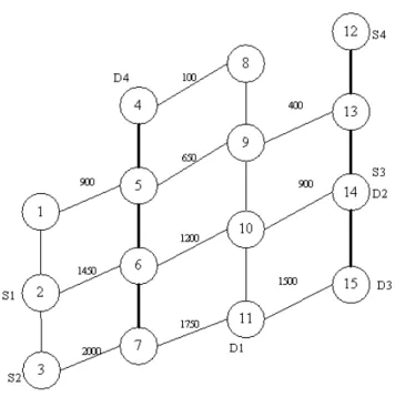
To illustrate our simulation, we snatch the network topology at a moment that was shown in Figure 2. In Figure 2, S1-S4 are four source nodes, D1-D4 are four destination nodes. The bold lines stand for the links whose bandwidth is 4.8MB while the rest lines are 2.4MB. The values appear on the edge represent the link time, which are in second. Requests are in the form of triple (s, d, breq), where s is the source node and d is the
destination node. SD pairs are selected randomly in the SD nodes. breq is the bandwidth
requested, and it is randomly selected between [1k, 4k].
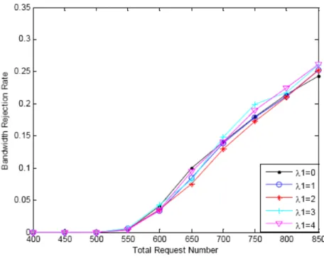
First, we discuss the parameters λ1 in (1) and λ2 in (2). The simulation results are
shown in Figures 3 to 6.
In Figure 3, the bandwidth rejection rate is the division of the sum of bandwidth rejected and the sum of bandwidth requested. It is ∑brej/
∑
breq, brej is the bandwidth
rejected.
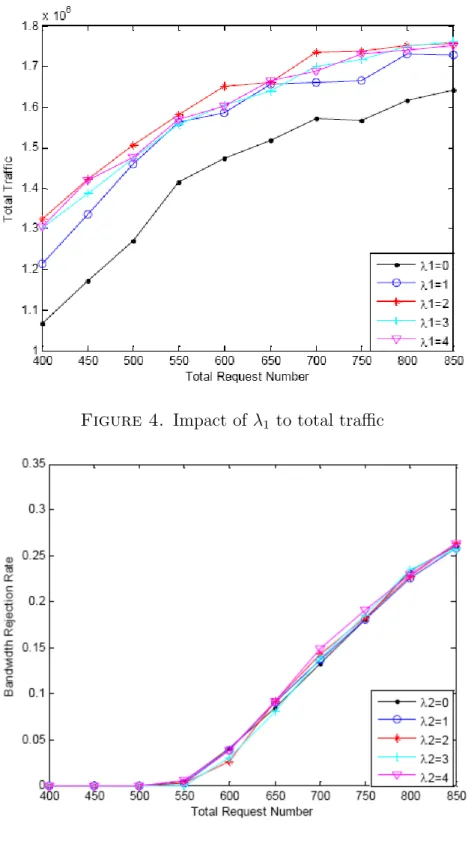
In Figure 4, the total traffic refers to the sum of communication traffic of all nodes. If we designate ci as the multiple of the bandwidth requested and the shortest link time of
the link in LSP in thei-th request, then the total traffic is∑ci. Andci can be formulized
as ci =breq∗M in(tlink(u, v)), (u, v)∈LSP.
It can be seen that it makes lower total traffic when λ1 equals 0. There are few
differences of bandwidth rejection rate when λ1 differs from each other. And it plays a
Figure 4. Impact of λ1 to total traffic
Figure 5. Impact of λ2 to bandwidth rejection rate
In Figures 5 and 6,λ2 in different values makes not too much impact to both bandwidth
rejection rate and total traffic. Whereas, there are still few differences and λ2 performs
better when it is 2.
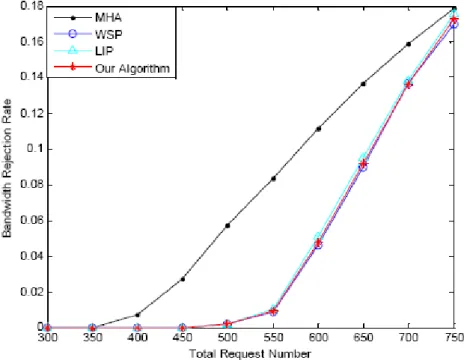
4.2. Simulation results. We compare with three algorithms to testify the performance of our algorithm. Two of them are greedy algorithms, including MHA and WSP, and the rest one is minimum interference algorithm, LIP. It should be noticed that we take both
Figure 6. Impact of λ2 to total traffic
Figure 7. Total traffic under the low-bandwidth rejection rate
λ1 and λ2 to be 2 in our simulation and run the simulation for 20 times for the results
below.
When under the condition of low-bandwidth rejection rate, the performances of four algorithms in total traffic and average traffic are in Figures 7 and 8. In Figure 8, the average traffic means the average traffic of a single LSP. It can be expressed as formulation
∑
ci/ ∑
Figure 8. Average traffic under the low-bandwidth rejection rate
Figure 9. Bandwidth rejection rate
Figures 7 and 8 show when the bandwidth rejection rate is low (less than 0.05), the total traffic and average traffic of four algorithms. It is obvious that our algorithm is better than the rest.
Figures 9, 10 and 11 are the simulation results of the bandwidth rejection rate, total traffic and average traffic when the request number increases.
Figure 10. Total traffic
It can be seen from Figure 9 that the MHA algorithm bandwidth rejection rate increases fastest. When the requests reach 450, all algorithms make bandwidth rejection. Except MHA, the rest three algorithms are almost the same.
We can conclude from Figures 10 and 11 that, our algorithm is better than the other three algorithms on total traffic and average traffic. Figure 10 shows that the total traffic increases slower as the LSP requests are more. In Figure 11, the average traffic of our algorithm goes down first and trends to smooth later. It is mainly because that the network goes saturated with more and more requests. The bandwidth of the rejection rate starts to rise, and the acceptance of LSP requests is less then. MHA, WSP and LIP do not consider link time, so the average traffic has less effect.
Figure 12 shows the average hops of four algorithms. Our algorithm makes more average hops compared with the other three algorithms, and LIP is higher than the WSP and MHA. MHA and WSP are roughly the same. The main reason is that the minimum interference algorithm which tries to reduce the path interference tends to increase the number of hops. Link time of links closing to the bottom of topology is longer, which further promotes our algorithm trends to more hops.
5. Conclusion. Due to the change of LEO satellite constellation network, the snapshot topology of time could resolve the problems. Whereas, it may lead to a bad situation. We proposed a new method with support of traffic engineering in this paper that avoids cutting the topology into time slices by defining a separate index for satellites. In practice, satellites can be designated a network address by the index and compute routing by existing routing component. The algorithm takes handover into account and takes the link time as a metric when routing. The simulation results show that the proposed algorithm has a good performance in rejection rate and traffic, though it is higher in average hops. Another topic for future study is rerouting when there are node fails or link fails. We will study more on rerouting based on the proposed routing algorithm.
Figure 11. Average traffic
Figure 12. Average number of hops
Acknowledgment. This work was supported by the Scientific Research Project of Liaon-ing Province Educational Committee (No. L2011217). The authors also gratefully ac-knowledge the helpful comments and suggestions of the reviewers, which have improved the presentation.
REFERENCES
[1] T. Zhang, J. Zhan and Z. Liu, Framework of MPLS based mobile satellite communication networks,
Globecom’97, pp.1903-1908, 1997.
[8] S. Kamei and T. Kimura, Evaluation of routing algorithms and network topologies for MPLS traffic engineering,Proc. of IEEE Global Communications Conference, pp.25-29, 2001.
[9] M. Kodialam and T. Lakshman, Minimum interference routing with applications to MPLS traffic engineering, Proc. of the 19th Annual Joint Conf. of the IEEE Computer and Communications Societies, pp.884-893, 2000.
[10] M. Werner, A dynamic routing concept for ATM-based satellite personal communication network,
IEEE Journal on Selected Areas in Communications, vol.15, no.8, pp.1636-1648, 1997.
[11] F. Xiao, L. Sun, X. Ye and R. Wang, Routing algorithm for MPLS traffic engineering in satellite network,Journal on Communications, vol.32, no.5, pp.104-111, 2011.
[12] I. F. Akyildiz, H. Uzunalio˘glu and M. D. Bender, Handover management in low earth orbit (LEO) satellite networks,Mobile Networks and Applications, vol.4, pp.301-310, 1999.
[13] S. Karapantazi, E. Papetrou and F. N. Pavlidou, Multiservice on-demand routing in LEO satellite networks,IEEE Transactions on Wireless Communications, vol.8, no.1, pp.107-112, 2009.
[14] E. Papetrou, S. Karapantazi and F. N. Pavlidou, Distributed on-demand routing for LEO satellite systems,Computer Networks, vol.51, pp.4356-4376, 2007.
[15] Z. Zheng and Y. Cui. A least interference path algorithm for MPLS traffic engineering, Chinese Journal of Computers, vol.30, no.6, pp.934-944, 2007.