Microsoft Private Cloud Fast Track
Deployment Guide on Huawei
Ver 1.0 HUAWEI Technologies Co., Ltd 1
Contents
1 Overview ... 3
1.1 Faster Deployment ... 3 1.2 Reduced Risk ... 3 1.3 Lower Cost-of-Ownership ... 42 What is Microsoft Private Cloud Fast Track? ... 5
3 HUAWEI Solution for Microsoft Private Cloud Fast Track ... 6
3.1 Reference Architecture ... 6
3.2 Hardware configuration ... 7
3.2.1 HUAWEI Tecal RH2288 V2 Server ... 7
3.2.2 HUAWEI OceanStor S5500T Storage System ... 9
3.2.3 HUAWEI Quidway S5700 Series Switch ... 10
3.3 Networking and VLAN Configuration ... 11
3.3.1 Network programming principle ... 11
3.3.2 Server Configuration ... 11
3.3.3 Network Switch Configuration ... 12
3.3.4 Storage System Configuration ... 13
4 Windows Server 2012 Fast Track Deployment Guide ... 15
4.1 Storage deployment ... 15
4.1.1 Login to HUAWEI ISM Management Console ... 15
4.1.2 Storage Pool Configuration ... 16
4.1.3 LUN configuration ... 19
4.1.4 Hosts configuration ... 20
4.1.5 Host Mapping Configuration ... 22
4.2 Server Deployment ... 25
4.2.1 Windows Server 2012 OS Installation ... 26
4.2.2 Network Adapter Configuration and NIC Teaming ... 26
4.2.3 Hyper-V, MPIO and Failover Clustering Feature Installation ... 30
4.2.4 Multipath I/O Configuration ... 34
4.3 iSCSI configuration ... 34
4.3.1 iSCSI Port Configuration for S5500T Storage System ... 34
4.3.2 iSCSI Port Configuration for Windows Server ... 35
Ver 1.0 HUAWEI Technologies Co., Ltd 2
4.4 Setup Active Directory Server ... 40
4.5 Join Domain ... 43
4.6 Live migration settings ... 43
4.7 Deploy Failover Cluster ... 45
4.7.1 Failover Cluster Validation ... 46
4.7.2 Failover Cluster Creation ... 48
4.7.3 Distributed Transaction Coordinator Configuration ... 50
4.8 Configure Clustered Shared Volume ... 52
4.9 Move Windows AD DS virtual Machine to CSV ... 55
4.10 Configure Windows AD DS as a Clustered Virtual Machine ... 57
Ver 1.0 HUAWEI Technologies Co., Ltd 3
1
Overview
The HUAWEI and Microsoft Window Server 2012 Hyper-V Private Cloud Fast Track solution provides a reference acrchitecture for building private clouds according to the customer’s organization’s unique requirements. This private cloud fast track solution combines Microsoft software, consolidated guidance, and validated configurations with HUAWEI computing power, network, and storage architectures; and value-added software components. This solution helps organizations implement private clouds with ease and confidence. Using this solution will bring your organization the following benefits, faster deployment, reduced risk, predictability, and a lower cost of ownership.
1.1
Faster Deployment
End-to-end architectural and deployment guidance.
Streamlined infrastructure planning due to predefined capacity.
Enhanced functionality and automation through deep knowledge of
infrastructure.
Integrated management for virtual machine and infrastructure deployment.
Simplify infrastructure and virtual machine deployment with integrated management.
Rapidly grow the infrastructure to adapt to market pressures by leveraging
the scalable design of the architecture.
1.2
Reduced Risk
Tested end-to-end interoperability for compute, storage, and network.
Deploy pre-defined out-of-box solutions based on a common cloud
architecture that has already been tested and validated.
High degree of service availability through automated load balancing
Ver 1.0 HUAWEI Technologies Co., Ltd 4
1.3
Lower Cost-of-Ownership
Near-zero downtime with exceptional fault tolerance, providing high
availability
Dynamic pooling that can enhance the use of virtualization resources with Hyper-V and with supported storage and network devices
Utilization of low-cost switches that consume less power and deliver high throughput for large bandwidth requirements
Benefit from high performance and scalability with HUAWEI Tecal RH2288
V2 Server and T Series Unified Storage solutions along with the Microsoft Windows Server 2012 operating system and Microsoft Hyper-V technology.
Ver 1.0 HUAWEI Technologies Co., Ltd 5
2
What is Microsoft Private Cloud Fast
Track?
MICROSOFT PRIVATE CLOUD FAST TRACK is a reference architecture for building private clouds that combines Microsoft software, consolidated guidance, and validated configurations with HUAWEI technology, including compute, storage, and network, as well as value-added software components.
Microsoft Hyper-V technology continues to gain competitive traction as a key cloud component in many customer virtualization environments. Hyper-V is included as a role in x64 versions of Windows Server 2012 Standard, and Datacenter editions. Microsoft Windows Server 2012 Hyper-V VMs support up to sixty-four virtual processors and 1TB of virtual memory.
Individual virtual machines (VMs) have their own operating system instance and are completely isolated from the host operating system as well as other VMs. VM isolation helps promote higher business-critical application availability while the Microsoft failover clustering feature, found in the Windows Server 2012 Standard and Datacenter Editions, can dramatically improve production uptimes.
Microsoft failover clustering helps eliminate single points of failure so users have near-continuous access to important server-based, business-productivity resources. In the event of physical or logical outages linked to unplanned failures or scheduled maintenance, VMs can automatically migrate to other cluster member nodes. As a result, clients experience little-to-no downtime. This seamless operation is attractive for organizations trying to create new business and maintain healthy service level agreements. Additionally, Microsoft failover clustering in Windows Server 2012 now supports in box NIC teaming to improve network fault tolerance and further improves physical resource utilization by load-balancing VMs across cluster member nodes in active/active configurations.
Ver 1.0 HUAWEI Technologies Co., Ltd 6
3
HUAWEI Solution for Microsoft Private
Cloud Fast Track
The HUAWEI and Microsoft Window Server 2012 Hyper-V Private Cloud Fast Track solution provides a reference acrchitecture for building private clouds according to the customer’s organization’s unique requirements. This private cloud fast track solution combines Microsoft software, consolidated guidance, and validated configurations with HUAWEI computing power, network, and storage architectures; and value-added software components.
3.1
Reference Architecture
This solution integrates all the components necessary for small infrastructure implementation. It consists of Microsoft Windows Server 2012 Hyper-V, HUAWEI Tecal RH2288 V2 series rack servers (RH2288 V2 for short), HUAWEI Quidway S5700 series network switches (S5700 for short) and HUAWEI OceanStor S5000T series unified storage systems (S5000T for short). All components are configured for high availability and reliability.
This solution provides a highly scalable and reliable platform and enables small businesses and branch offices to take advantage of the power of cloud computing without the complexity entailed in designing and implementing custom solutions. The reference architecture for HUWEI solution for Microsoft Private Cloud Fast Track 3 is shown as follow.
Ver 1.0 HUAWEI Technologies Co., Ltd 7
Figure 3-1Reference Architecture for Microsoft Private Cloud Fast Track
VLAN A --- iSCSI VLAN B --- VMvSwitch
VLAN C --- LiveMigration & Heartbeat
Internal Management Network Dedicated Network for VM Dedicated Network for iSCSI
Dedicated Network for Live Migration & Heartbeat
Internal Network Switch External Access Network Switch
WS2012 Failover Cluster: 2 * HUAWEI RH2288 V2 Rack Server Storage System: HUAWEI OceanStor S5500T Unified Storage System Data Center Switch
Internal Network Switch is used for internal management of servers and storage systems;
External Access Netwok Switch is used for end users to connect to virtual machines;
The Internal Network Switch and External Access Network Switch are not included in this Fast Track solution.
3.2
Hardware configuration
As shown in Figure 3-1, Two HUAWEI RH2288 V2 rack servers are used as Windows Server 2012
failover cluster nodes which implements server high availability;
Two HUAWEI S5700 network switches are used to implement the
redundancy for network link including iSCSI connections between servers and storage system, external access connections for virtual machine and internal connections for live migration and heartbeat;
The HUAWEI S5500T storage system is used as datastore, which is designed
with redundant controllers that can advoid Single Point of Failure.
3.2.1
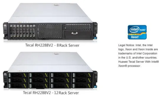
HUAWEI Tecal RH2288 V2 Server
2-Ver 1.0 HUAWEI Technologies Co., Ltd 8
socket rack server. Featuring two Intel® Xeon® E5-2600 series processors, the RH2288 V2 provides a memory capacity of 768 GB and a storage capacity of 38 TB, making it an ideal product for critical services and cloud computing.
Figure 3-2HUAWEI Tecal RH2288 V2 Series Rack Server
The detailed information for HUAWEI RH2288 V2 servers used in the HUAWEI and Microsoft Private Cloud Fast Track solution is shown in Table 3-1.
Table 3-1HUAWEI Tecal RH2288 V2 Server Detailed Information Hardware Description
HUAWEI Tecal RH2288 V2 Rack Server
CPU: 2 * Intel Xeon E5-2600 series with 8 cores and Hyper-Threading technology, 32 physic cores available in total Memory: 8 * 16 GB or 16 * 16 GB DDRIII
Hard Disk: 2 * 300 GB 2.5 inch or 3.5 inch SAS Disk Network Adapter:
4 * built-in Intel 82580 Gigabyte network ports 4 * extended Intel 82576 Gigabyte network ports 8 intel 1Gps network ports in total
For more information about HUAWEI Tecal RH2288 V2 series rack server, please visit:
http://enterprise.huawei.com/en/products/itapp/server/rh-series-rack-servers/hw-124935.htm
Ver 1.0 HUAWEI Technologies Co., Ltd 9
3.2.2
HUAWEI OceanStor S5500T Storage System
HUAWEI OceanStor S5000T series unified storage system is a new-generation storage product for mid-range and high-end storage applications. It boasts integration of block-level and file-level data storage. Support for a variety of storage protocols, and GUI-based central storage management. Delivering leading performance, enhanced efficiency, maximized return on investment, and all-in-one solutions, and the S5000T series is ideally applicable to scenarios such as large-database OLTP/OLAP, high-performance computing, digital media, Internet applications, central storage, backup, disaster recovery, and data migration.
Figure 3-3HUAWEI OceanStor S5500T Unified Storage System
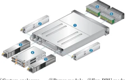
The internal architecture of HUAWEI OceanStor S5500T unified storage system meets the principle of high availability. Full component redundancy prevents single points of failure. Data coffer and file system mirror improve system reliability. The dual Active/Active controller provides interruption-free redundancy to ensure operational reliability and availability.
Figure 3-4HUAWEI OceanStor S5500T Storage System inside architecture
①System enclosure ②Power module ③Fan-BBU module
Ver 1.0 HUAWEI Technologies Co., Ltd 10
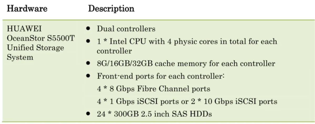
The detailed information for HUAWEI S5500T storage system used in the HUAWEI and Microsoft Private Cloud Fast Track solution is shown in Table 3-2; Table 3-2HUAWEI S5500T Series Unified Storage System Configuration
Hardware Description HUAWEI OceanStor S5500T Unified Storage System Dual controllers
1 * Intel CPU with 4 physic cores in total for each controller
8G/16GB/32GB cache memory for each controller Front-end ports for each controller:
4 * 8 Gbps Fibre Channel ports
4 * 1 Gbps iSCSI ports or 2 * 10 Gbps iSCSI ports 24 * 300GB 2.5 inch SAS HDDs
For more information about HUAWEI S5000T series unified storage system, please visit :
http://enterprise.huawei.com/en/products/itapp/storage/san-product/hw-131886.htm
3.2.3
HUAWEI Quidway S5700 Series Switch
The S5700 series ethernet switches (S5700 for short) are next-generation energy-saving switches developed by HUAWEI to meet the demand for high-bandwidth access and Ethernet multi-service aggregation. Based on cutting-edge hardware and HUAWEI Versatile Routing Platform (VRP) software, the S5700 provides a large switching capacity, high reliability (double power slots and hardware Ethernet OAM), and high-density GE ports to accommodate 10 Gbps upstream transmissions. It also supports Energy Efficient Ethernet (EEE) and iStack. The S5700 can be used in various enterprise network scenarios. For example, it can function as an access or aggregation switch on a campus network, a gigabit access switch in an Internet data center (IDC), or a desktop switch to provide 1000 Mbps access for terminals.
Figure 3-5HUAWEI Quidway S5700 Series Network Switch
Ver 1.0 HUAWEI Technologies Co., Ltd 11
HUAWEI & Microsoft Private Cloud Fast Track solution is shown in Table 3-3; Table 3-3HUAWEI Quidway S5700 Network Switch configuration
Hardware Description
HUAWEI Quidway S5700 Network Switch
48 * 10/100/1000BASE-T Ethernet ecetrical interfaces 4 * 10 Gbps interfaces on the front card
For more information about HUAWEI Quidway S5700 series network switch, please visit:
http://enterprise.huawei.com/en/products/network/switch/data-center-switch/hw-131612.htm
3.3
Networking and VLAN Configuration
3.3.1
Network programming principle
To implement easy management and access security, it is recommended to isolate internal management netwok and external network from each other.
In this solution, four network zones are deployed accoding to different usages, shows as follows.
Management Network
The Management Network is the internal network used to manage servers, network switches and storage systems;
Heartbeat and Live Migration Network
The Heartbeat and Live Migration Network is a dedicated network used between Windows failover cluster nodes as heartbeat and live migration network for virtual machines;
Dedicated Network for Accessing Virual Machine
This network is the dedicated network for end users or customers to access their virtual machines from external network;
Dedicated Network for iSCSI Storage
This network is the dedicated network used as iSCSI connection between server hosts and iSCSI storage systems.
3.3.2
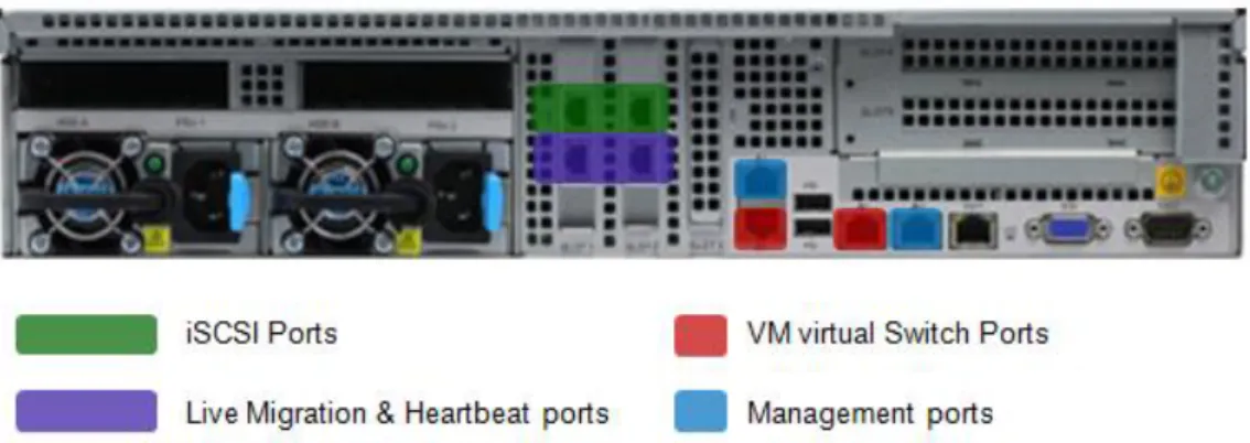
Server Configuration
On each HUAWEI Tecal RH2288V2 server, eight 1Gbps Ethernet network ports are configured including 2 ports using as iSCSI connection to storage system, 2 ports using as a NIC team for management console, 2 ports using as virtual machine virtual switches and last 2 ports using as a NIC team for virtual
Ver 1.0 HUAWEI Technologies Co., Ltd 12
machine live migration and heartbeat.
The detailed configuration information for HUAWEI Tecal RH2288 V2 is shown as follow.
Figure 3-6Networking Configuration for HUAWEI RH2288 V2 Servers
As shown in Figure 3-5, eight network ports are divided into four groups, and each two ports in a group are used as a team located on different network adapter, which can implement high availability for network access. This configuration can effectively avoid single point of failure even one network adapter is down.
3.3.3
Network Switch Configuration
As shown in Feature 3-1, two HUAWEI S5700 48-port 1GbE Ethernet switches are deployed in this Fast Track solution.
On each HUAWEI S5700 switch, 3 VLANs are deployed, including VLAN A-iSCSI, VLAN B-VMvSwitch and VLAN C-LiveMigration&Heartbeat.
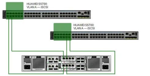
Figure 3-7Network VLAN division on HUAWEI S5700 Switches
Ver 1.0 HUAWEI Technologies Co., Ltd 13
Table 3-4VLAN description
VLAN Name Description
VLAN A - iSCSI VLAN Used for iSCSI storage traffic. VLAN B - VMvSwitch VLAN Used for VM communication. VLAN C -
LiveMigration&Heartbeat VLAN Used for cluster heartbeat and VM Live Migration and failover cluster heartbeat.
iSCSI Storage Network (VLAN A)
There are two controllers on the HUAWEI OeanStor S5500T storage system, and each controller has four 1Gbps Ethernet ports for iSCSI traffic. The iSCSI ports are used for communication between storage system and servers. Each switch will host a VLAN for iSCSI to isolate storage traffic from other data traffic occurring on the switches.
VM switch Network(VLAN B)
This network is used for communication between virtual machines and external network. One NIC team with two 1Gbps network ports is created through Windows Server 2012 NIC teaming feature to provide fault tolerance and load-balancing for communication between virtual machines and external network.
Heartbeat & Live Migration Network(VLAN C)
This network is used for heartbeat and virtual machine live migration between clustered server nodes.
3.3.4
Storage System Configuration
The OceanStor S5500T storage system is designed with redundant controllers to prevent Signal Point of Failture.
Ver 1.0 HUAWEI Technologies Co., Ltd 14
As shown in Figure 3-7,
Each S5500T’s controller is connected to two HUAWEI S5700 switch’s VLAN
A, which is dedicated for iSCSI connection; even one of the netwok switch is down, the other switch can take over all the businesses, without single point of failure.
Each S5700 switch is connected to both two controllers so that even one controller is down, the other controller can take over all the businesses, without single point of failure.
Ver 1.0 HUAWEI Technologies Co., Ltd 15
4
Windows Server 2012 Fast Track
Deployment Guide
4.1
Storage deployment
The following step-by-step processes with screenshots are shared to illustrate how to configure HUAWEI OceanStor S5500T unified storage syetem with ISM.
ISM: The integrated storage management software for HUAWEI storage.
4.1.1
Login to HUAWEI ISM Management Console
End users can login to HUWEI ISM console according to the following step.
Step 1 Open web browser such as Internet Explorer or Mozillar Firefox;
Ver 1.0 HUAWEI Technologies Co., Ltd 16
Step 3 Click Login button, input Username and Password, then click Login button;
Step 4 Then the web browser would turn to the storage system management console.
4.1.2
Storage Pool Configuration
As the beginning of configuring storage system, the pools must be created on the storage device. After storage pools are successfully generated, multiple disks can provide the virtual storage space according to actual RAID levels. In this way, the storage device can dynamically increase the storage space quota within a specified range based on the space utilization on the application server, fulfilling on-demand storage space allocation of optimal utilization.
Ver 1.0 HUAWEI Technologies Co., Ltd 17
Step 1 In the storage system management console, click “Resource Allocation” icon in the right plane, then click “Storage Pools” icon in the left plane of Resource Allocation page;
Step 2 Click “Create” button on the Storage Pools page;
Step 3 On the “Name” page of Create Storage Pool Wizard, input Storage Pool Name and Description, then click Next button;
Step 4 On the “Set Storage Tier Information” page of Create Storage Pool Wizard, select needed storage tier, disk type, RAID Policy, hot spare policy and disks, then click Next button;
Ver 1.0 HUAWEI Technologies Co., Ltd 18
A storage pool is divided into three layers based on their performance level, including Tier 0, Tier 1 and Tier 2. Tier 0 is high performance layer using SSDs; Tier 1 is medium performance layer using SAS disks to balance the performance and capacity, and Tier 2 is low performance layer using NL-SAS or SATA disks. Table 4-1Smart Tier Feature Characteristics
Layer Disk Feature
Tier 0 Solid State Disk High Performance
Tier 1 SAS Balanced Performance and Capacity
Tier 2 SATA or NL-SAS Capacity
For each layer, 5 RAID policies are supported including RAID 0,3,5,6 and 10; And for RAID 3 and RAID 5, three data protection policies are supported including
Ver 1.0 HUAWEI Technologies Co., Ltd 19
2D+1P, 4D+1P and 8D+1P, D stands for data, P stands for date protection; For RAID 6, two data protection policies are supported including 4D+2P and 8D+2P.
Step 5 On the “Summary” page of Create Storage Pool Wizard, click Finish button.
Step 6 On the “Result” page of Create Storage Pool Wizard, click Close button to finish the creation of storage pool.
----End
4.1.3
LUN configuration
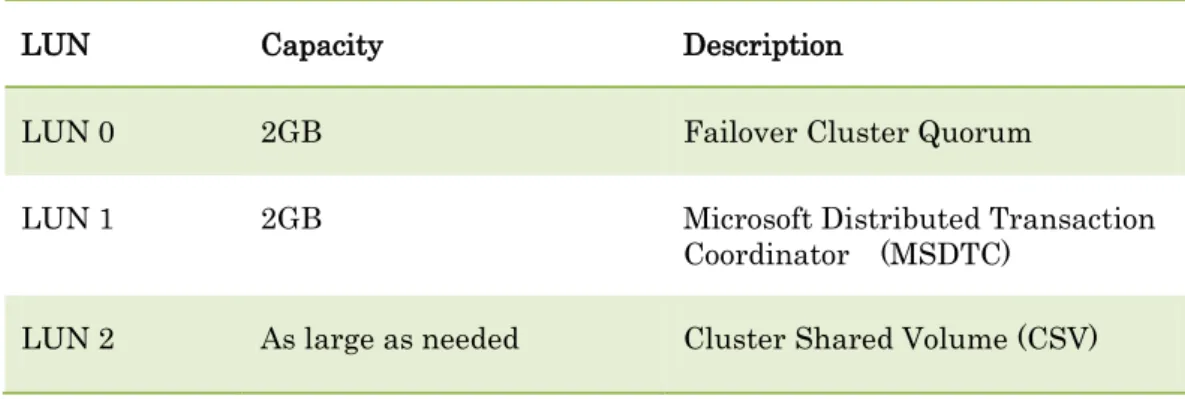
In this Fast Track solution, 3 LUNs should be created in the storage pool, one for Quorum, the other for Microsoft Distributed Transaction Coordinator (MSDTC), and the last one would be used as Cluster Shared Volume (CSV) for Windows Server 2012 failover cluster. 2GB is enough for both Quorum and MSDTC LUNs; the capacity for CSV could be as large as customers’ requirements.
The definition for each LUN is shown as follow.
Table 4-2LUN Definition for Windows Server 2012 Failover Cluster
LUN Capacity Description
LUN 0 2GB Failover Cluster Quorum
LUN 1 2GB Microsoft Distributed Transaction
Coordinator (MSDTC) LUN 2 As large as needed Cluster Shared Volume (CSV)
End users can create LUNs according to the following steps.
Step 1 In the storage system management console, click “Resource Allocation” icon in the right plane, then click “Storage Pools” icon in the left plane of Resource Allocation page;
Step 2 Right-click the storage pool that would used to create LUNs for Fast Track, select “Create LUN” option;
Ver 1.0 HUAWEI Technologies Co., Ltd 20
Step 3 On the “Create LUN” page, enter the LUN name, for instance Quorum, LUN description, Capacity, number of LUNs, storage pool, then click “OK” button. Each LUN just needs 2GB capacity.
Step 4 On the “Results” page, click Close button.
Step 5 Repeat the above steps to create LUN for MSDTC, and then these two LUNs would be in the list.
----End
4.1.4
Hosts configuration
In this Fast Track solution, two servers are used as failover cluster nodes, therefore two hosts should be created for storage host mapping view.
Ver 1.0 HUAWEI Technologies Co., Ltd 21
Step 1 In the system management console, click the “Host” icon in the right plane, and the click “Host” icon in the left plane;
Step 2 On the “Host” page, click “Create” button;
Step 3 On the “Set Host Information”page of Create Host Wizard, input host name, description, IP address and location information, select needed OS, and then click “Next” button;
Ver 1.0 HUAWEI Technologies Co., Ltd 22
Step 4 On the “Configure Initiator” page of Create Host Wizard, select the relevant iSCSI initiators for host server, then click “Next” button. If iSCSI Initiators are not configured, it could be configured later.
Step 5 On the “Summary” page of Create Host Wizard, click “Finish” button;
Step 6 On the “Result” page of Create Host Wizard, click “Close” button to finish creating host;
Step 7 Repeat the above steps to create second host for another host server, then the hosts added would be in the list;
----End
4.1.5
Host Mapping Configuration
Before finishing configuration of storage system, the host mapping view must be created. End users can create the host mapping view according the following steps.
Step 1 Login to HUAWEI ISM storage system management console, click “Host” icon and then click “Mapping View” icon on the left plane;
Ver 1.0 HUAWEI Technologies Co., Ltd 23
Step 2 On the “Mapping View” page, click “Create” button;
Step 3 On the “Set Mapping View” page of Create Mapping View Wizard, input mapping view name and description, click “Next” button;
Step 4 On the “Add Hosts ” page of Create Mapping View Wizard, select hosts to add to this mapping view, click “Next” button;
Ver 1.0 HUAWEI Technologies Co., Ltd 24
Step 5 On the “Add LUNs” page of Create Mapping View Wizard, select the LUNS to add to this host mapping view, then click “Next” button;
Step 6 On the “Add Snapshots” page of Create Mapping View Wizard, click Next button;
Step 7 On the “Summary” page of Create Mapping View Wizard, the host mapping view name, description, mapped host, mapped volume and mapped snapshot would be listed, click “Finish” button;
Ver 1.0 HUAWEI Technologies Co., Ltd 25
Step 8 On the “Result” page of Create Mapping View Wizard, click Close button to finish creating mapping view;
----End
4.2
Server Deployment
The server deployment process includes the following steps. Windows Server 2012 OS installation
Ver 1.0 HUAWEI Technologies Co., Ltd 26
Hyper-V role, MPIO and Failover Clustering Feature installation NIC Teaming Configuration
Hyper-V Virtual Switch Configuration
4.2.1
Windows Server 2012 OS Installation
Before installing OS, confirm extended Intel 82578 Gigabyte NIC is installed in each server, and confirm each NIC ports is connected to their dedicated S5700 switch ports.
Install Windows Server 2012 Datacenter Edition, and run Windows Update to insure any new patches are installed.
Windows Server 2012 Datacenter Edition allows unlimited Windows virtual machine rights on the host servers and is the preferred version for building private cloud configurations.
Windows Server 2012 Standard Edition now supports clustering as well, but only provides licensing rights for up to two Windows virtual machines (additional licenses would be needed for additional VMs). Windows Server 2012 Standard Edition is intended for physical servers that have very few or no virtual machines running on it.
4.2.2
Network Adapter Configuration and NIC Teaming
In this Fast Track solution, to implent network high availability, three NIC teams will be created, the function for each NIC team is shown as follows.
MgmtTeam
This NIC team is used to implement physical host management.
vSwitchTeam
This NIC team is created to support virtual machine communication, and a vSwitch for Hyper-V would be created over this team.
LiveMigrationTeam
This NIC team is created to support virtual machine live migration and cluster heartbeat.
End users can configure NIC Teaming according to the following steps.
Before configuring NIC teaming, it is recommended to change the network port name according to different usage such as VMvSwitch ports, iSCSI Ports, Management Console ports, so that in the NIC teaming process, it is easy to distinguish according to the port name.
Ver 1.0 HUAWEI Technologies Co., Ltd 27
For instance, shown as follow, eight network ports are in the list divided into four groups according to the port name, so that when creating NIC teaming, it is easy to distinguish which ports would be use as iSCSI team, which ports would be used as Live Migration team, etc.
Step 1 Start Server Manger, click “All Servers” item on the left plane, right-click the server needed NIC teaming, and then select “Configure NIC Teaming” option;
Step 2 On the “NIC Teaming” page, all the network adapters would be in the list, shown as follow;
Ver 1.0 HUAWEI Technologies Co., Ltd 28
Step 3 Right-click the network adapter that would be teamed, select “Add to New Team” option;
Step 4 Input the Team Name, and select additional network port to add to this NIC teaming, then click “OK” button;
Ver 1.0 HUAWEI Technologies Co., Ltd 29
Step 5 Repeat the above steps to finish all NIC teaming process, then all the NIC teaming would be in the team list.
Step 6 Repeat the above steps on another host server, then all the teaming configuration would be listed as follow.
Step 7 When finishing NIC teaming, configure IP addressed for each NIC team port. ----End
Ver 1.0 HUAWEI Technologies Co., Ltd 30
4.2.3
Hyper-V, MPIO and Failover Clustering Feature
Installation
In the Fast Track solution, the following role and features must be installed.
Hyper-V
Multipath I/O (MPIO)
Failover Clustering
End users can install these role and features according to the following steps.
Step 1 Start Server Manger, on the Server Manger, click “Add roles and features” item;
Step 2 On the “Select server roles” page of Add Roles and Features Wizard, select “Hyper-V” option;
Ver 1.0 HUAWEI Technologies Co., Ltd 31
Step 3 On the Add Roles and Features Wizard page, click “Add Features” button to return back to Select server role page, then click “Next” button;
Step 4 On the Select features page of Add Roles and Features Wizard, select Failover Clustering option;
Step 5 On the Add Roles and Features Wizard page, click Add Features button and return back to Select features page;
Ver 1.0 HUAWEI Technologies Co., Ltd 32
Step 6 On the “Select features” page of Add Roles and Features Wizard, select “Multipath I/O” option, then click “Next” button;
Step 7 On the “Hyper-V” page of Add Roles and Features Wizard, click Next button;
Step 8 On the “Create Virtual Switches” page of Add Roles and Features Wizard, select the NIC team used for Virtual Machine switch, then click “Next” button;
Ver 1.0 HUAWEI Technologies Co., Ltd 33
Step 9 On the “Virtual Machine Migration” page of Add Roles and Features Wizard, select “Allow this server to send and receive live migrations of virtual machines” and select “Use Kerberos option for Authentication protocol” option, then click “Next” button;
Step 10 On the “Default Stores” page of Add Roles and Features Wizard, select default location for virtual hard disk files, then click “Next” button;
Step 11 On the “Confirm installation selections” page of Add Roles and Features Wizard, check if Hyper-V, Failover Clustering, Multipath I/O features and their appendix components are in the list, then click “Install” button;
Step 12 On the Installation progress page of Add Roles and Features Wizard, click Close button and reboot system to finish the feature installation.
Ver 1.0 HUAWEI Technologies Co., Ltd 34
4.2.4
Multipath I/O Configuration
Multipath I/O is used to provide balanced and fault tolerant data traffic paths from Windows server to storage system. For Microsoft Multipath I/O, the Distributed Scan Management plug-in (DSM) is needed, and Windows Server 2012 supports customized Distributed Scan Management plug-in (DSM) by storage vendors. In this solution, default DSM for Multipath I/O from Microsoft is used.
End users can configure Multipath I/O according the following steps.
Step 1 Start Server Manger, click “Tools” button, then select “MPIO” option;
Step 2 On the “MPIO Properties” dialog, select “Discover Multi-Paths” tab, select “Add support for iSCSI devices” option, then click “Add” button to reboot server to finish MPIO configuration.
----End
4.3
iSCSI configuration
4.3.1
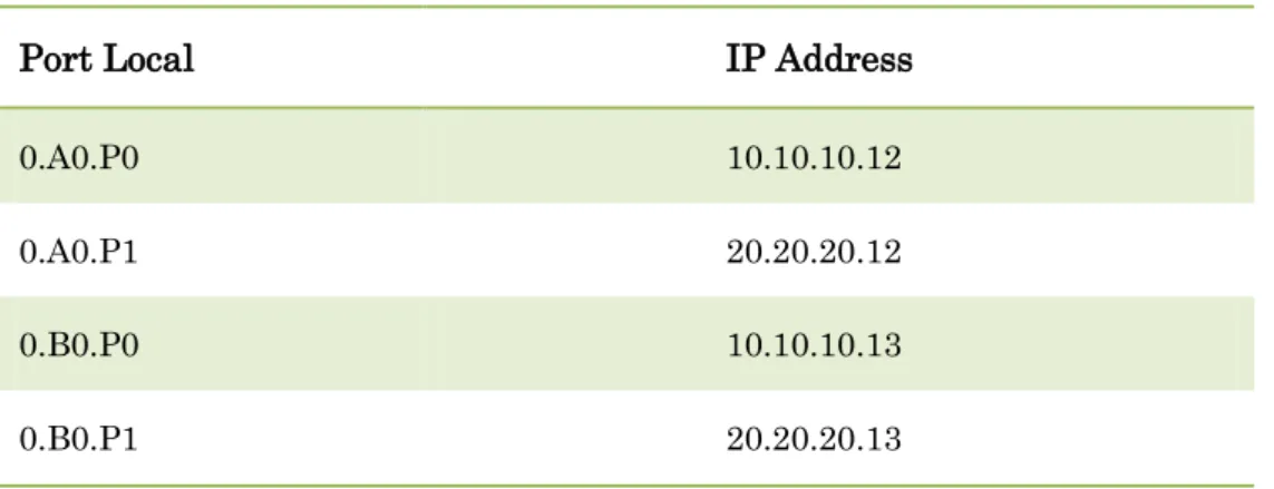
iSCSI Port Configuration for S5500T Storage System
In this Fast Track solution, two network ports are used for iSCSI data traffic on each controller. The following table shows the reference IP address of each port. Table 4-3 iSCSI Port IP Address Configuration
Port Local IP Address
0.A0.P0 10.10.10.12
0.A0.P1 20.20.20.12
0.B0.P0 10.10.10.13
0.B0.P1 20.20.20.13
End users can configure the IP addresses for iSCSI ports according to the following steps.
Step 1 Login to the HUAWEI ISM system management console, click “Device View” icon on the bottom; then on the Dashboard, click the rotate icon to change the appearance to backplane;
Ver 1.0 HUAWEI Technologies Co., Ltd 35
Step 2 Click each iSCSI port used for Fast Track, on the “iSCSI Host Port” page, click “Modify” button;
Step 3 On the “iSCSI Host Port” page, enter the IPv4 address and subnet mask, then click “OK” button.
Step 4 Repeat above steps to finish all iSCSI ports ip address configuration. ----End
4.3.2
iSCSI Port Configuration for Windows Server
Ver 1.0 HUAWEI Technologies Co., Ltd 36
Server and remote iSCSI targets, such as storage system. Before using it, we shoule open it and configure connection settings.
End users can configure the iSCSI initator on Windows Server 2012 according to the following steps.
Step 1 Start Server Manager, click “Tools” button and select “iSCSI Initiator” option;
Step 2 On the “Microsoft iSCSI” dialog, click “Yes” button to start Microsoft iSCSI service;
Step 3 On the “iSCSI Initiator Properties” dialog, select “Targets” tab, input Target IP address, and click “Quick Connect” button;
Step 4 If the iSCSI target is available, there would be the Quick Connect information for login successfully, then click “Done” button;
Ver 1.0 HUAWEI Technologies Co., Ltd 37
Step 5 Repeat above step 3 and step 4 until all the iSCSI target IP addresses on storage system are connected sucessfully;
Ver 1.0 HUAWEI Technologies Co., Ltd 38
----End
4.3.3
Add iSCSI Session to Mapping View
End users can add iSCSI sessions to mapping view according the following steps.
Step 1 Login to HUAWEI ISM storage system management console, click Host icon on the right plane, then click Host icon on the left;
Step 2 On the “Host” page, select the host server that needed to add iSCSI initiator, and click “Configure Initiator” button;
Step 3 On the “Initiator Configuration” dialog, select needed iSCSI initiator in the iSCSI initiator list, then click the Move Down button, and click “OK” button to finish iSCSI initator mapping.
Ver 1.0 HUAWEI Technologies Co., Ltd 39
Step 4 When finishing the above process, the iSCSI initiator would be in the list.
Ver 1.0 HUAWEI Technologies Co., Ltd 40
4.4
Setup Active Directory Server
Active Directory Domain Controller (AD DC) is the necessary component of the Windows failover cluster, because the Windows server must be part of the Active Directory Domain. For Windows Server 2012, the AD DC could be on a virtual machine located on the Windows Server 2012 failover cluster.
If Windows Active Directory already exists, it could be used as well.
If customers have no existing Windows Active Directory, Windows Active Directory could be created on either physic host or virtual machine.
End users can configure the AD DC on Windows Server 2012 virtual machine according to the following steps.
Step 1 Create a virtual machine, install Windows Server 2012 Operating System, then configure the IP address, netmask, gateway and default DNS;
Step 2 Login to the Windows Server 2012 virtual machine, start Server Manager, and click “Add roles and features”;
Step 3 On the Select server roles page of Add Roles and Features Wizard, select “Active Directory Domain Services”, click “Add Features” button, then click “Next” button;
Step 4 On the “Select features” page of Add Roles and Features Wizard, click “Next” button;
Step 5 On the “Active Director Domain Services” page of Add Roles and Features Wizard, click “Next” button;
Ver 1.0 HUAWEI Technologies Co., Ltd 41
Step 6 On the “Confirm installation selections” page of Add Roles and Features Wizard, select “Restart the destination server automatically if required” option, then click “Install” button;
Step 7 On the “Installation Progress” page of Add Roles and Features Wizard, click “Close” button;
Step 8 Login to system after restarting, start Server Manager again, and click “AD DS” item on the left plane, and click “More” on the right plane;
Step 9 On the “All Server Task Details” dialog, click “Promote this server to a domain”;
Step 10 On the “Deployment Configuration” page of Active Directory Domain Services Configuration Wizard, select “Add a new forest” option, input the Root domain name, then click “Next” button;
Ver 1.0 HUAWEI Technologies Co., Ltd 42
Step 11 On the “Domain Controller Options” page of Active Directory Domain Services Configuration Wizard, Select “Windows Server 2012” for Forest functional level and Domain functional level, select “Domain Name System server” and “Global Catalog” (GC), then input password and click “Next” button;
Step 12 On the “DNS Options” page of Active Directory Domain Services Configuration Wizard, click “Next” button;
Step 13 On the “Additional Options” page of Active Directory Domain Services Configuration Wizard, input The BIOS domain name, then click “Next” button;
Step 14 On the “Path” page of Active Directory Domain Services Configuration Wizard, input the Database folder, Log file folder and SYSCOL folder, then click “Next” button;
Step 15 On the “Review” Options page of Active Directory Domain Services Configuration Wizard, check over the detailed selection information, then click “Next” button;
Ver 1.0 HUAWEI Technologies Co., Ltd 43
Step 16 On the “Prerequisites Check” page of Active Directory Domain Services Configuration Wizard, view the results, then click “Install” button;
Step 17 When finishing the above process, the Windows Server 2012 Active Directory Domain Services is installed successfully.
----End
For more information about Windows Server 2012 Active Directoty, please visit Microsoft official website:
http://technet.microsoft.com/zh-cn/library/jj574166.aspx
4.5
Join Domain
According to the requirement of Microsoft Windows Server 2012 failover cluster, each Windows Server host must join the dedicated domain. Thedetailed steps for joining Windows Activer Directory are not listed, please see the Microsoft websites.
4.6
Live migration settings
To implement live migration feature in Windows Server 2012 failover cluster, end users can configure the live migration settings according to the following steps.
Step 1 Select one NIC port or a NIC team used for live migration and configure IP address on each failover cluster node. For instance, in the following configuration, two 1Gbps NIC ports (including LiveMigrationPort1 and LiveMigrationPort2) are used as a NIC team (LiveMigrationTeam), and the team port was configured with IP 30.30.30.x.
Step 2 Open Failover cluster manager, connect to the cluster and right-click the “Networks” option on the left plane, select “Live Migration Settings” option in the right-click menu;
Ver 1.0 HUAWEI Technologies Co., Ltd 44
Step 3 On the “Live Migration Settings” dialog, select the network adapter which is configured for live migration and then click “Apply” and “OK” buttons.
Step 4 Open Hyper-V manager, connect to all Hyper-V hosts of failover cluster, right-click each Hyper-V host, and select “Hyper-V Settings” in the right-right-click menu.
Ver 1.0 HUAWEI Technologies Co., Ltd 45
Step 5 In the Hyper-V Settings dialog, select “Live migrations” in left plane, and enable incoming and outgoing live migration, choose Kerberos as the default authentication protocol, set simultaneous live migration number, and choose imcoming live migration network IP address, then click “Apply” and “OK” button.
Step 6 When finishing above steps, the configuration for live migration is complete successfully, Clustered virtual machines could be live migrated through the above NIC port or team.
----End
4.7
Deploy Failover Cluster
A failover cluster is a set of independent computers that work together to increase the availability of server roles. The clustered servers are connected by physical cables and by software. If one of the nodes fails another node begins to take over this server’s services (a process known as failover).
Before creating Windows Server 2012 failover cluster, the Failover Clustering feature must be installed first. The installing steps please visit: 4.2.3 Hyper-V, MPIO and Failover Clustering Feature Installation.
The deployment for Failove cluster consists of three stages, including validation stage, creation stage and High availability configuration.
Ver 1.0 HUAWEI Technologies Co., Ltd 46
configuration, network configuration and so on; the creation stage is the real section to create Windows Server Failove cluster.
End users can create failover clusters according to the following steps.
4.7.1
Failover Cluster Validation
Step 1 Before validating and creating failover cluster, scan disk LUNs used for Microsoft Quorum and MSDTC on each Windows server node.
Step 2 Start Server Manger, click “Tools” button, then select “Failover Cluster Manager” option;
Ver 1.0 HUAWEI Technologies Co., Ltd 47
Step 4 On the “Before You Begin” page of Validate a Configuration Wizard, click Next button;
Step 5 On the “Select Servers or a Cluster” page of Validate a Configuration Wizard, input server name, then click “Next” button;
Step 6 On the”Testing” Options page of Validate a Configuration Wizard, select “Run all tests (recommended)” option, then click “Next” button;
Step 7 On the”Test Selection” page of Validate a Configuration Wizard, select all components, then click “Next” button;
Step 8 On the “Confirmation” page of Validate a Configuration Wizard, click “Next” button, the validationg process would start;
Ver 1.0 HUAWEI Technologies Co., Ltd 48
Step 9 The validation result would be shown as the following figure;
----End
4.7.2
Failover Cluster Creation
After completing validation of hardware configuration successfully, end users can create Failover Cluster In the same wizard.
Step 1 On the “Summary” page of Validate a Configuration Wizard, if the validation completes successfully, select “Create the cluster now using the validated nodes” option, then click “Finish” button to start the Create Cluster Wizard;
Ver 1.0 HUAWEI Technologies Co., Ltd 49
Step 2 On the “Before you Begin” page of Create Cluster Wizard, click “Next” button;
Step 3 On the “Access Point for Administring the Cluster” page of Create Cluster Wizard, input Cluster name and IP address, and then click “Next” button;
In environments where DHCP reservations are used, this dialog with a cluster IP will be slightly different to support the DHCP configuration.
Ver 1.0 HUAWEI Technologies Co., Ltd 50
Step 4 On the” Confirmation” page of Create Cluster Wizard, select “Add all eligible storage to the cluster”, then click “Next” button to start creating failover cluster;
Step 5 When finishing above process, the failover cluster would be created successfully. On the “Summary” page of Create Cluster Wizard, click “Finish” button;
----End
4.7.3
Distributed Transaction Coordinator Configuration
In Windows Server systems, the Microsoft Distributed Transaction Coordinator (MS DTC) component provides support for active/active clusters in which a clustered MS DTC resource coordinates distributed transactions across a Windows failover cluster group.
In order to implement active-active cluster feature, it is recommended to install the Microsoft Distributed Transaction Coordinator (MSDTC) after creating failover cluster.
The Microsoft Distributed Transation Coordinator is optional for Windows Server failover cluster, but it is recommended to be installed for active-active cluster, detailed information please see:
http://technet.microsoft.com/zh-cn/library/cc730992(v=ws.10).aspx
DTC supports distributed applications that perform transactions. A transaction is a set of related tasks, such as updates to databases, that either success or fail as a unit.
End users can install MSDTC according to the following steps.
Step 1 Start Failover Cluster Manager, connect to failover cluster, then right-click Roles item, select “Configure Role” option in right-click menu;
Ver 1.0 HUAWEI Technologies Co., Ltd 51
Step 2 On the “Select Role” page of High Availability Wizard, select Distributed Transaction Coordinator (DTC), then click “Next” button;
Step 3 On “Client Access Point” page of High Availability Wizard, Input the name and IP address, then click “Next” button;
Step 4 On “Select Storage” page of High Availability Wizard, select the storage volume prepared for Microsoft DTC specially.and then click “Next” button;
Ver 1.0 HUAWEI Technologies Co., Ltd 52
Step 5 When finishing the above process, the configuration for Windows Server 2012 failover cluster high availability is complete successfully.
----End
4.8
Configure Clustered Shared Volume
Cluster Shared Volumes (CSVs) in a Windows Server 2012 failover cluster allow multiple nodes in the cluster to simultaneously have read-write access to the same LUN (disk) that is provisioned as an NTFS volume. With CSVs, clustered roles can fail over quickly from one node to another node without requiring a change in drive ownership, or dismounting and remounting a volume. CSVs also help simplify managing a potentially large number of LUNs in a failover cluster. End users can configure CSVs according to the following steps.
Step 1 Create storage LUN used as Clustered Shared Volume and add this LUN to mapping view;
Step 2 Scan this disk LUN on each Windows Server host;
Step 3 Online and Initiate this disk LUN, and then create NTFS file system for this disk LUN;
Step 4 Start Failover Cluster Manager, click “Storge” item on the left plane, then right-click the Disk item and select “Add Disk” option;
Ver 1.0 HUAWEI Technologies Co., Ltd 53
Step 5 On the “Add Disk” dialog, select the needed disk, then click “OK” button;
Step 6 Back to Failover Cluster Manager, right-click the disk added before, select “Add to Cluster Shared Volumes” option;
Ver 1.0 HUAWEI Technologies Co., Ltd 54
Step 7 A moment later, this clustered shared volume would be in the list;
Step 8 When finishing the above process, the clustered shared volume has been added successfully. Then in C:\ClusterStorage directory, the clustered shared volume would be in the list, shown as follow.
Ver 1.0 HUAWEI Technologies Co., Ltd 55
----End
4.9 Move Windows AD DS virtual Machine to CSV
To implent high availability for Active Directory Domain Services (AD DS) if this AD DS is in the failover cluster, it is recommended to move AD DS virtual machine to clustered shared volume, end users can follow the steps to move AD DS virtual machine to CSV, during the moving process, AD DS virtual machine must be shutdown.
If Windows Active Directory Domain Service already exists on virtual machine out of the failover cluster, the step for moving Active Directory to CSV is optional.
Step 1 Start Hyper-V manager;
Step 2 Right-click “Hyper-V Manager” item in the left plane and click Connect to Server option;
Step 3 On the “Select Computer” dialog, select” Local computer” option or select “Another computer” and input computer name, then click “OK” button;
Step 4 After connecting to Hyper-V server that hosts AD DS virtual machine, the virtual machine would be in the list. Then shutdown AD DS virtual machine.
Ver 1.0 HUAWEI Technologies Co., Ltd 56
Step 5 Right-click AD DS virtual machine, select “Move” option;
Step 6 On the “Before You Begin” page of Move VM Wizard, click “Next” button;
Step 7 On the” Choose Move Type” page of Move VM Wizard, select “Move the virtual machine’s storage” option, then click “Next” button;
Step 8 On the “Choose” Options for Moving Storage page of Move VM Wizard, select “Move all of the virtual machine’s data to a single location” option, then click “Next” button;
Step 9 On the” Choose a new location for virtual machine” page of Move VM Wizard, click “Browse” button to select the location for store virtual machine. Here select the clustered shared volume to store AD DS so that the AD DS virtual machine could live migrate amont the failover cluster nodes, then click “Next” button;
Step 10 On the “Completing Move Wizard” page of Move VM Wizard, check detailed information and then click “Finish” button to performing the move;
Ver 1.0 HUAWEI Technologies Co., Ltd 57
Step 11 When finishing the above process, the location for storing AD DS virtual machine would change to clustered shared volume.
----End
4.10 Configure Windows AD DS as a Clustered Virtual
Machine
After moving location for storing AD DS virtual machine to clustered shared volume, the following step is to configure the AD DS virtual machine as a clustered virtual machine.
If Windows Active already exists on virtual machine out of the failover cluster, the step for moving Active Directory to CSV is optional.
End users can configure it according to the following steps.
Step 1 Start Failover Cluster Manager, and connect to the cluster;
Step 2 Right-click “Roles” item in the left plane, select “Configure Role” in the right-click menu;
Step 3 On the” Select Role” page of High Availability Wizard, select “Virtual Machine” option, then click “Next” button;
Step 4 On the “Select Virtual Machine” page of High Availability Wizard, select AD DS virtual machine, then click “Next” button;
Step 5 On the “Confirmation” page of High Availability Wizard, Click “Next” button;
Step 6 On the” Summary” page of High Availability Wizard, Click “Finish” button if configuring virtual machine successfully.
Step 7 After finishing the above process, the AD DS server has been configured as a clustered virtual machine. Then the AD DS would be in the Roles list.
Ver 1.0 HUAWEI Technologies Co., Ltd 58
5
Terms and Abbreviations
AD DS Active Directory Domain Services
CSV Clustered Shared Volume
HA High Availability
IDC Internet Data Center
iSCSI SCSI over IP
ISM Integrated Management Software of HUAWEId Storage
System
LUN Logical Unit Number
MSDTC Microsoft Distributed Transaction coordinator
MPIO Multipath I/O
NIC Network Interface card
NL SAS Nearline Serial Attached SCSI(Disk)
SAS Serial Attached SCSI(Disk)
SSD Solid State Disk