Freescale Semiconductor
White Paper
Wireless infrastructure equipment manufacturers must balance minimizing deployment costs against fulfilling demands for next generation network services. Significant infrastructure investment in recent years has resulted in amortization playing a key role in future network evolution. Reusing existing infrastructure allows equipment
manufacturers to offer operators a road map for long term evolution (LTE) that will reduce operating and capital expenditures.
Freescale Semiconductor’s solutions enable network planners full flexibility when upgrading the GERAN or UTRAN to offer users additional services. This paper details the existing protocol and interface requirements for transport on 2G- and 3G-wireless base stations. It also presents Freescale’s solution for extending the lifetime of deployed equipment while also solving next generation data rate and feature set requirements, thus creating an extensible, IP-anywhere mobile network capable of offering ubiquitous mobile broadband.
Document Number: WBSEVOLWP Rev. 1, 02/2009
Contents
1. Deployed Network Interface Card Architectures . . . . 2
2. Pseudowire and Aggregation . . . 8
3. Wireless Wireline Colocation . . . 9
4. Long Term Evolution . . . 10
5. Conclusion . . . 13
6. Revision History . . . 14
Wireless Base Station Evolution
2G and 3G Colocation Solution For LTE Access
by Networking and Multimedia Group Freescale Semiconductor, Inc. East Kilbride, Scotland
Deployed Network Interface Card Architectures
1
Deployed Network Interface Card Architectures
This section details the protocol and interface requirements on base station transport cards. It begins with GSM network interface cards and concludes with 3GPP Release 7 BTS network interface cards. It focuses on the physical layer 1 to layer 2 connection requirements and the protocol manipulation on the network interface card, up to and including layer 4.
1.1
2G—GSM Base TransceiverStation (BTS)
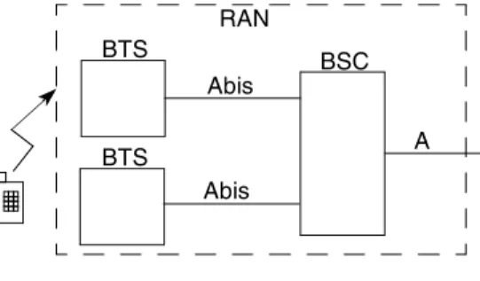
Figure 1 shows the GSM RAN architecture.
Figure 1. GSM RAN Architecture
The GSM base transceiver station (BTS) connects to the base station controller (BSC) by an E1 connection known as the Abis interface. The Abis interface is a channelized time-division multiplexing (TDM) link in which each user connection typically requires 8 Kbps or 16 Kbps depending on the modulation scheme. The layer 2 protocol present on each user connection is either transparent or HDLC.
Additional E1 links from the BSC to the BTS may be present to allow services offered by GPRS and EDGE, such as web browsing and file download. These E1 links cannot be bundled. The additional E1 links for GPRS and/or EDGE do not change the basic architecture of the BTS or the protocol requirements on an E1.
The A interface connects the BSC to the core network by TDM links, which are typically multiple E1 links. When deploying a mobile network in a greenfield site, most operators today choose GSM with GPRS or GSM with GPRS plus EDGE (GERAN) as this technology is mature, proven, and allows the operators to seed and test the new market in a controllable, cost-effective manner. This strategy facilitates a road map to 3G and beyond, as explained in the following sections.
1.2
3G—Release 99 Base Station (Node B)
Because the Abis interface uses a channelized TDM, bandwidth is wasted in periods of low-density traffic as statistical multiplexing cannot be adopted. The unused bandwidth cannot be reused; therefore, operators must absorb this cost. Furthermore, low-density nodes are not capable of easing the pressure on
higher-density nodes. Scalability is also an issue because E1 bundling is not possible.
To solve the inherent limitations posed by TDM transport, various schemes have been created. For example, idle periods of speech can be removed from the RAN physical transport or smart compression algorithms can be used. Smart voice compression and packet data can adopt discontinuous transmission over the air and backhaul to allow bandwidth gains.
BTS BTS BSC Abis Abis A RAN
Deployed Network Interface Card Architectures However, this architecture cannot be optimized indefinitely. It saturates at 384 Kbps for a single user. E1/T1 leased lines are expensive, so unused bandwidth fruitlessly increases operating expenditures. A more efficient transport is essential for handling the increased number of voice users coexisting with enhanced data services.
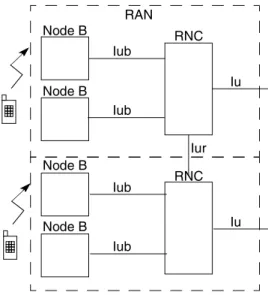
Thus, in order to provide users the same experience on the move that they enjoy at home, a new RAN architecture is required. For this task, the 3GPP defined the UMTS Terrestrial Radio Access Network (UTRAN). Figure 2 details the architecture of the UTRAN.
Figure 2. UTRAN Architecture
Initially, the architecture appears identical to the GERAN. However, the air interface compression offers greater spectral efficiency than found in GSM. Additionally, the bearer on the Iub interface is IP or ATM, not TDM. This has the advantage of allowing statistical multiplexing, which enables efficient bandwidth control of the network by the operator. There is no longer unused bandwidth on the Iub solely due to the transport bearer.
Another notable difference between the UTRAN and the GERAN is the inclusion of a physical interface, Iur, between the RNCs, which control the base stations. This interface can offload the core network bandwidth from handovers and simplifies signaling.
Release 99 is predominantly ATM based; thus network planners typically deploy the following on the Iub: • Single E1 for low-density coverage cells
• Bundled E1 links where a cost-effective method is needed for more bandwidth than GSM Abis • E3 or OC3/STM1 for metro Node B in densely populated areas
Node B Node B RNC Iub Iub Iu Iur RNC Node B Node B Iub Iub Iu RAN
Deployed Network Interface Card Architectures
The Iub transport layer protocol stack (layer 2 only) is shown in Figure 3.
Figure 3. Iub Transport Layer 2 Protocol Stack
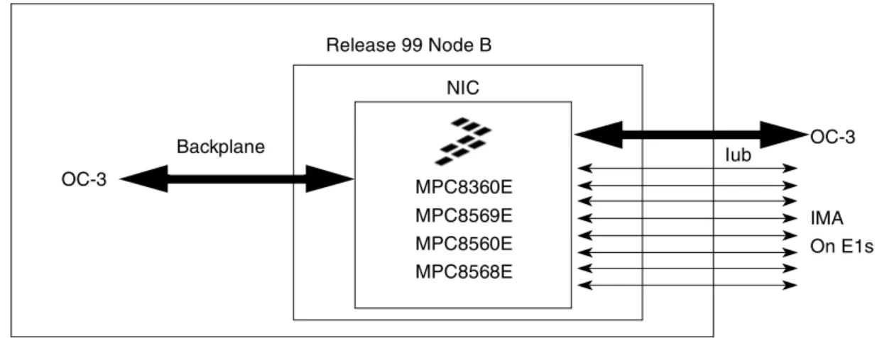
The physical layer connectivity will typically be OC/3 or IMA bonded E1 links (typically 8 or 16). A network interface card (NIC) architecture is shown below in Figure 4.
Figure 4. Network Interface Card Architecture
The network interface card must be capable of terminating AAL2 and AAL5 while also performing AAL2 switching in order to interwork backplane and Iub traffic. The Iub interface controlling processor must be capable of providing IMA and UTOPIA in addition to a UTOPIA bus for the backplane. Freescale PowerQUICC™ processors are capable of these functions.
3GPP mandates that WCDMA be compatible with GSM, thus allowing network planners to utilize already deployed 2G network infrastructure as components in their 3G network. Therefore, colocation of
interconnected 2G and 3G base stations is a common practice, allowing operators to amortize their 2G equipment. ATM AAL5 AAL2 Physical Layer MPC8360E MPC8569E MPC8560E NIC Release 99 Node B Iub OC-3 MPC8568E IMA On E1s Backplane OC-3
Deployed Network Interface Card Architectures
Figure 5 shows the colocated GSM BTS architecture.
Figure 5. Colocated GSM BTS on WCDMA Transport
The GSM BTS can be located on the 3G RAN by using a dedicated TDM to connect the 2G BTS to the 3G Node B. The RNC is capable of handling GSM and WCDMA user traffic formats, allowing the GSM BTS to share the transport on the Iub and therefore to colocate. The Node B network interface card must be capable of the following:
• GSM versus WCDMA classification
• ATM-bearer-to-TDM-bearer interworking (AAL1 CES)
If fractional E1 links are used on the Iub, the majority of timeslots are dedicated for the ATM bearer and are terminated on the Node B. The remaining timeslots on the Iub are allocated to the BTS. The Node B performs TDM-bearer-to-TDM-bearer forwarding. This allows 3G traffic on the ATM bearer to use statistical multiplexing while 2G traffic is allocated the bandwidth required at this site.
1.3
3G—Release 5 Base Station (Node B)
3GPP Release 5 can be characterized by the introduction of IP as the predominant bearer in the RAN. Release 5 does not mandate any architectural changes to the RAN transport interfaces. As shown in
Figure 6, the main difference compared to Release 99 is the transport protocols.
Figure 6. Release 5 Iub Transport Protocol Stack
The physical layer connection for low-density base stations is still bonded E1 links. The bonding protocol is MLPPP because this offers less header overhead than ATM when encapsulating IP, thus allowing efficient usage of the Iub bandwidth. For a metro Node B, IP is transported over Ethernet.
RNC Iu Iur Node B Node B Iub Iub RAN Abis BTS IP MLPPP Ethernet Physical Layer
Deployed Network Interface Card Architectures
The introduction of IP in the RAN was gradual, and various base station architectures were deployed.
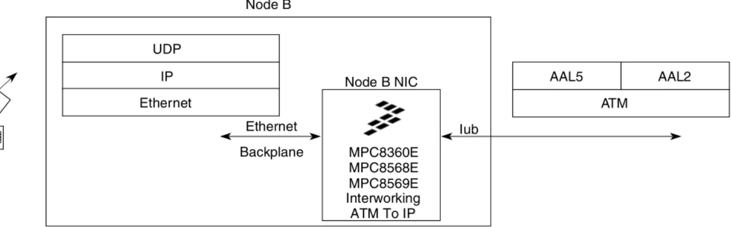
Figure 7 details a Node B architecture where the IP transport network terminates at the network interface card.
Figure 7. IP Network Reach Internal to Node B
The network interface card is responsible for protocol conversion from the ATM bearer to an IP backplane. This allows network providers to introduce IP into the RAN transport while leveraging the existing ATM transport deployed in Release 99. Therefore, the Node B NIC protocol processor must be capable of ATM- bearer-to-IP backplane interworking.
Figure 8 shows the architecture with full IP transport in the RAN.
Figure 8. IP Transport in the 3G RAN
For low-density areas, the Iub is physically composed of multiple E1 links bonded using MLPPP, similar to IMA for Release 99 ATM transport. For a metro Node B, the Iub is typically a fast (100baseT) or Gigabit Ethernet connection.
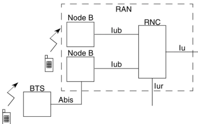
Release 5 was designed to be compatible with Release 99 and GSM, paving the way for various colocation schemes. Figure 9 shows a 3G Release 5 Node B with a colocated Release 99 Node B. The Release 5 Node
Node B Iub Ethernet Node B NIC MPC8360E MPC8568E Interworking ATM To IP IP Ethernet UDP ATM AAL5 AAL2 Backplane MPC8569E Node B Iub Ethernet Node B NIC MPC8360E MPC8568E Interworking IP To IP (NAT) IP Ethernet UDP MLPPP Ethernet Backplane IP UDP MPC8569E
Deployed Network Interface Card Architectures B performs IP-bearer-to-ATM-bearer interworking while also forwarding traffic to its internal backplane (as shown in Figure 8).
Figure 9. Release 5 Node B with Colocated Release 99 Node B
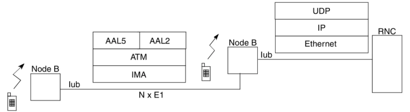
Figure 10 shows a Release 5 Node B capable of colocating multiple 2G BTSs.
Figure 10. Release 5 Node B with Colocated GSM BTSs
The Release 5 Node B performs IP-bearer-to-TDM-bearer interworking using IETF defined pseudowire encapsulation. The 2G BTS TDM frames are aggregated and encapsulated in PWE and then transported over IP/Ethernet on the Iub. Freescale PowerQUICC processors are capable of this function, specifically the MPC8360E, MPC8568E and MPC8569E as these devices support multi-protocol interworking.
1.4
3G—Release 6 and 7 Base Station (Node B)
3GPP Release 6 and Release 7 do not mandate any architectural changes in the UTRAN backhaul; thus
Figure 2 remains valid. These releases mainly deliver increased user-connection rates in the RAN, which allows operators to offer additional services, such as high-speed packet access, to their customers. The colocation schemes detailed in Section 1.2, “3G—Release 99 Base Station (Node B),” and Section 1.3, “3G—Release 5 Base Station (Node B),” also still apply for 3GPP Release 6 and Release 7.
Node B Iub Iub Node B IP Ethernet UDP RNC ATM IMA AAL2 AAL5 N x E1 Node B Iub Abis BTS IP Ethernet UDP RNC E1 Abis BTS E1
Pseudowire and Aggregation
2
Pseudowire and Aggregation
The transmission is a major contributor to the RAN’s capital and operating expenditures. When upgrading or deploying the RAN, operators often face the decision of leasing lines or deploying their own
transmission infrastructure. Any savings that can be realized in this domain are highly attractive to them. Therefore, numerous solutions have been created to minimize transmission related costs. One such scheme is to provide a homogenous backhaul in a heterogeneous network (2G and 3G) by aggregating low-density base stations on a common shared backhaul.
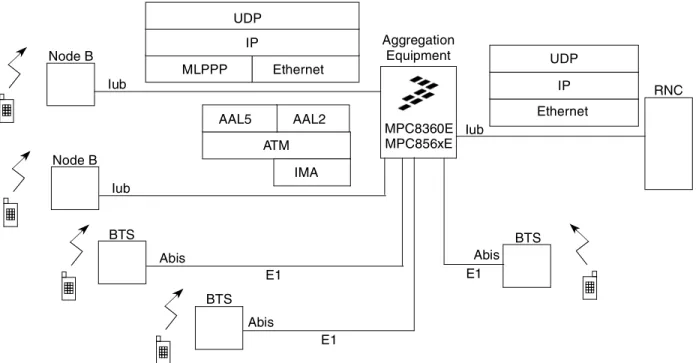
Figure 11 details a colocation scheme utilizing an external aggregation system. The aggregation equipment is housed at or close to the base station site.
Figure 11. 2G and 3G Base Station Colocation Using External Aggregation Unit
Although Figure 11 illustrates the full functionality of the aggregation equipment, it is unlikely every scenario depicted would be required to operate concurrently. Typically, a higher-density Node B is deployed, and a small number of lower-density base stations are colocated by the aggregation equipment at the same site. A saving is achieved because only one backhaul physical link is required, leased or otherwise.
The aggregation equipment must be capable of the following:
• ATM aggregation
• Pseudowire
• Interworking between ATM, TDM and IP bearers
Freescale Semiconductors PowerQUICC processors perform this function. The MPC8569E can be deployed in locations where a higher density of base stations are aggregated or where IPsec is required in the transport layer. The MPC8569E offers generic protocol and interface interworking (beyond layer 4)
Node B Iub Abis BTS IP Ethernet UDP RNC E1 Abis BTS E1 Iub Aggregation Equipment MPC8360E MPC856xE Abis BTS E1 MLPPP Ethernet IP UDP Node B Iub ATM IMA AAL2 AAL5
Wireless Wireline Colocation coupled with a Power Architecture core capable of operating at frequencies greater than 1GHz. Data and control plane traffic can optionally be encrypted (IPsec) using the device’s integrated security engine. The MPC8569E is therefore a very balanced, cost effective and powerful solution to operators’ and equipment manufacturers’ protocol interworking, colocation, bearer interoperability and security needs.
3
Wireless Wireline Colocation
At some access sites, it is cost effective for the operator to share the access transport with DSL technology. Because DSL physical interfaces are mass deployed, they are generally less expensive to lease than E1/T1.
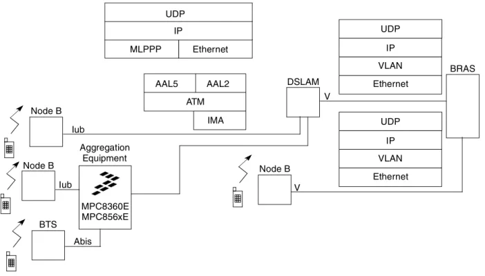
Figure 12 details how 3G transport can realize network connectivity using the DSLAM V-interface.
Figure 12. RAN Utilizing DSL V-Interface
In Figure 12, the Iub is connected to the DSLAM line card, and the line card behaves very much like the aggregation equipment depicted in Section 2, “Pseudowire and Aggregation.” Indeed, the aggregation equipment may also be used to interface directly to the DSLAM. Another alternative is to connect the Node B directly to the BRAS; in this case, the Iub is internal to the base station. In both cases, the Node B NIC protocol processor must be capable of:
• Iub transport to DSL V-interface interworking
• VLAN tag management
Freescale Semiconductor’s PowerQUICC processors are capable of these functions. DSLAM V Iub Node B VLAN Ethernet BRAS MLPPP Ethernet IP UDP ATM IMA AAL2 AAL5 UDP IP Node B V VLAN Ethernet UDP IP Aggregation Equipment MPC8360E MPC856xE Abis BTS Node B Iub
Long Term Evolution
3.1
Metro Ethernet Access
A similar strategy to utilizing DSL access infrastucture can be realized in regions where metro Ethernet is prevalent. The colocated 2G and 3G transport can reach the network by using the metro Ethernet
infrastructure similarly to how it utilizes the DSL V-interface. In this case MPLS must be supported by the aggregation equipment.
Again Freescale Semiconductor’s PowerQUICC processors are capable of these functions.
4
Long Term Evolution
The underlying goal of LTE is ubiquitous mobile broadband, and the RAN topology has evolved to meet this goal. Due to the increased data rates available to subscribers (up to 300 Mbps), it requires substantial processing power to control the RAN centrally. The RNC or BSC would be expensive, both in terms of deploying and running costs.
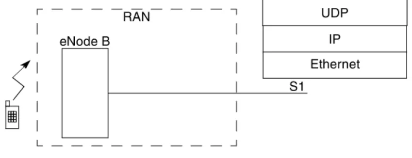
To overcome this, 3GPP defined LTE as incorporating a system architecture evolution (SAE) that simplifies the access network. Distributed control is used in the RAN, removing the necessity for a centralized controlling entity such as an RNC or BSC. Figure 13 shows the LTE RAN.
Figure 13. LTE RAN Architecture
In the LTE RAN architecture, the access interface is called the S1 and the base station is called the eNode B (enhanced Node B). The access bearer is IP, which provides a flat architecture for all service
types—even voice is transported over IP (VoIP). This simplifies the access protocol processing
requirements both at eNode B and the core network. Essentially, the network is packet switched. The lack of a centralized controlling entity reduces round trip times to levels acceptable for new services such as gaming. However, operators desiring to fully amortize their infrastructure investments must still colocate legacy BTS or Node B. Additionally, they must provide a secure access network where users’ data content is protected. Thus the following three requirements pose significant problems to equipment manufacturers:
• Increased control plane processing on the base station
• Amortization of legacy base stations (interworking with legacy 2G and 3G base stations) • Access network security
Foremost in equipment manufacturers’ minds are factors such as cost, power, protocol processing and interworking, network management, reuse of existing equipment, and platforms capable of remote
eNode B S1 RAN IP Ethernet UDP
Long Term Evolution software upgrades. Freescale’s QorIQ™ communication platforms built on Power Architecture™ technology and QUICC Engine™ products solve these issues.
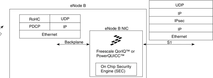
Figure 14 details the LTE transport and protocol requirements and illustrates how Freescale microprocessors can be utilized on the network interface card.
Figure 14. LTE eNode B Transport Solution
The on-chip security engine can encrypt users’ data and fully supports IPsec, which is a requirement mandated by 3GPP on the S1. The security engine can also be used to provide encryption on the backplane. Hence, the LTE network interface card must be capable of the following:
• IPsec
• IP to IP forwarding (backplane to S1 interworking)
• IP to encrypted backplane forwarding (S1 to encrypted backplane interworking)
The security engine can also be used for application data or software. Thus, software images can be protected during both remote download and power-on based system boot.
In terms of control plane processing requirements, QorIQ platforms and PowerQUICC microprocessors are built on Power Architecture technology. Therefore, precompiled control stacks can run on both products. The base station site determines control plane performance requirements, which in general are as follows:
• Low-density areas favor a PowerQUICC processor deployment as they require fewer CPU cycles for control.
• Metro sites favor QorIQ platforms as the control plane processing needs are higher. PDCP RoHC eNode B S1 eNode B NIC Freescale QorIQ™ or PowerQUICC™ IP Ethernet UDP Ethernet Backplane IPsec IP IP UDP On Chip Security Engine (SEC)
Long Term Evolution
For colocation, Figure 15 details the connectivity and interworking requirements at a site already housing a 2G and/or a 3G base station.
Figure 15. LTE eNode B Transport Solution with Colocation
In addition to the functions defined in Figure 14, colocation requires that the LTE network interface card be capable of:
• LTE IP bearer to 2G TDM bearer interworking, using pseudowire encapsulation
• LTE IP bearer to 3G Release 99 bearer interworking, using either pseudowire or IP-to-ATM interworking
• LTE IP bearer to 3G Release 5-7 bearer interworking, using either pseudowire or IP forwarding
• IPsec
Freescale Semiconductor’s QorIQ platforms combined with QUICC Engine technology provides solutions for the vast majority of deployment scenario facing operators. QUICC Engine technology provides protocol-to-protocol conversion as well as generic interface conversion. This allows TDM-based protocol (Abis, IMA/ATM, or MLPPP)-to-IP interworking, which solves the colocation issue. The MPC8569E additionally offers IPsec offload which can be used in 3G and LTE access. Thus colocation of TDM and ATM bearers can be processed concurrently with user and control traffic requiring IPsec.
For long term evolution, traffic can be processed by the Power Architecture core(s) present on the QorIQ platforms and the PowerQUICC devices. Both platforms support on chip security. Thus a single software image can decide whether the site needs colocation, security or bearer interworking. This simplifies network management and allows remote software upgrades to be pushed to deployed equipment.
eNode B S1 Node B Iub Abis BTS E1 Ethernet IPsec IP IP UDP MLPPP Ethernet IP UDP ATM IMA AAL2 AAL5
Conclusion
5
Conclusion
A region’s demographics and politics plays a role in how network planners provision a road map for long term evolution. Operators will not accept an LTE deployment that makes their 2G and 3G equipment redundant. Because transmission is a major contributor to operating and capital expenditures, colocation is often a necessity. It allows the 2G and 3G base station to share the physical access with the LTE base station, thus amortizing legacy equipment.
Freescale Semiconductor’s industry-leading QorIQ communication platforms built on Power Architecture technology and QUICC Engine products solve the interface, performance, security and protocol
requirements posed by LTE access. These products strike the right balance between user-plane protocol processing and control-plane processing. They can be used in a metro eNode B (multi sector) and a low-density eNode B (single sector). The scalability offered by these solutions coupled with the ability to download one software image on both platforms is a highly attractive proposition to equipment
manufacturers and operators alike. These platforms also make it possible to reuse legacy infrastructure seamlessly with long term evolution. This allows operators to fully amortize their initial infrastructure investment. Network planners and equipment manufacturers thus have the freedom to offer solutions to operators that cover all of the deployment scenarios detailed in Table 1.
This document has shown that Freescale solutions allow operators to leverage investments made in 2G and 3G access infrastructure as part of their LTE deployment strategy. Broadband anywhere, anytime is an LTE goal that Freescale Semiconductor is making a commercial reality.
Table 1. Deployment Scenarios Product Matrix
Deployment Scenario Freescale Microprocessor
2G BTS With GPRS and Edge Greenfield PowerQUICC Microprocessors With QUICC Engine Technology
3G Release 99 Node B Greenfield PowerQUICC Microprocessors With QUICC Engine Technology
3G Release 99 Node B With Colocated 2G BTS PowerQUICC Microprocessors With QUICC Engine Technology
3G Release 5, 6 or 7 Node B Greenfield PowerQUICC Microprocessors With QUICC Engine Technology
3G Release 5-7 With Colocated 3G Release 99 or 2G BTS PowerQUICC Microprocessors With QUICC Engine Technology
CAPEX/OPEX Reducing Transmission Equipment (PWE, Base Station Aggregation, Generic Bearer Interworking etc.)
PowerQUICC Microprocessors With QUICC Engine Technology
LTE Greenfield Power Architecture QorIQ Platforms or PowerQUICC
Microprocessors With QUICC Engine Technology
LTE With Colocated 2G BTS or 3G Node B Power Architecture QorIQ Platforms With QUICC Engine
Revision History
6
Revision History
Table 2 provides a revision history for this white paper.
Table 2. Document Revision History
Rev.
Number Date Substantive Change(s)
1 02/2009 Added IPsec and MPC8569E paragraphs to Section 2, “Pseudowire and Aggregation.”
Revision History
Document Number: WBSEVOLWP Rev. 1
Information in this document is provided solely to enable system and software implementers to use Freescale Semiconductor products. There are no express or implied copyright licenses granted hereunder to design or fabricate any integrated circuits or integrated circuits based on the information in this document.
Freescale Semiconductor reserves the right to make changes without further notice to any products herein. Freescale Semiconductor makes no warranty, representation or guarantee regarding the suitability of its products for any particular purpose, nor does Freescale Semiconductor assume any liability arising out of the application or use of any product or circuit, and specifically disclaims any and all liability, including without limitation consequential or incidental damages. “Typical” parameters which may be provided in Freescale Semiconductor data sheets and/or specifications can and do vary in different applications and actual performance may vary over time. All operating parameters, including “Typicals” must be validated for each customer application by customer’s technical experts. Freescale Semiconductor does not convey any license under its patent rights nor the rights of others. Freescale Semiconductor products are not designed, intended, or authorized for use as components in systems intended for surgical implant into the body, or other applications intended to support or sustain life, or for any other application in which the failure of the Freescale Semiconductor product could create a situation where personal injury or death may occur. Should Buyer purchase or use Freescale Semiconductor products for any such unintended or unauthorized application, Buyer shall indemnify and hold Freescale Semiconductor and its officers, employees, subsidiaries, affiliates, and distributors harmless against all claims, costs, damages, and expenses, and reasonable attorney fees arising out of, directly or indirectly, any claim of personal injury or death associated with such unintended or unauthorized use, even if such claim alleges that Freescale Semiconductor was negligent regarding the design or manufacture of the part. How to Reach Us:
Home Page:
www.freescale.com
Web Support:
http://www.freescale.com/support
USA/Europe or Locations Not Listed:
Freescale Semiconductor, Inc. Technical Information Center, EL516 2100 East Elliot Road
Tempe, Arizona 85284 1-800-521-6274 or +1-480-768-2130
www.freescale.com/support
Europe, Middle East, and Africa:
Freescale Halbleiter Deutschland GmbH Technical Information Center
Schatzbogen 7 81829 Muenchen, Germany +44 1296 380 456 (English) +46 8 52200080 (English) +49 89 92103 559 (German) +33 1 69 35 48 48 (French) www.freescale.com/support Japan:
Freescale Semiconductor Japan Ltd. Headquarters ARCO Tower 15F 1-8-1, Shimo-Meguro, Meguro-ku Tokyo 153-0064 Japan 0120 191014 or +81 3 5437 9125 [email protected] Asia/Pacific:
Freescale Semiconductor China Ltd. Exchange Building 23F
No. 118 Jianguo Road Chaoyang District Beijing 100022 China
+86 10 5879 8000
For Literature Requests Only:
Freescale Semiconductor Literature Distribution Center P.O. Box 5405 Denver, Colorado 80217 1-800 441-2447 or +1-303-675-2140 Fax: +1-303-675-2150 LDCForFreescaleSemiconductor @hibbertgroup.com
Freescale and the Freescale logo are trademarks or registered trademarks of Freescale Semiconductor, Inc. in the U.S. and other countries. All other product or service names are the property of their respective owners. The Power Architecture and Power.org word marks and the Power and Power.org logos and related marks are trademarks and service marks licensed by Power.org.
![Pentacarbonyl[N,N dimethyl N′ (5 {2 [5 (4 pyridylethynyl)thiophen 2 yl]vinyl}thiophen 2 ylmethylene)benzene 1,4 diamine]tungsten(0)](data:image/gif;base64,R0lGODlhAQABAIAAAP///wAAACH5BAEAAAAALAAAAAABAAEAAAICRAEAOw==)