AENSI Journals
Australian Journal of Basic and Applied Sciences
ISSN:1991-8178Journal home page: www.ajbasweb.com
Corresponding Author: Chen Kean Tack, Universiti Teknologi Malaysia, Faculty of Electrical Engineering, 81310 Skudai, Johor, Malaysia.
E-mail: [email protected]
A 32-bit FPGA-based Single Precision Floating-point Hybrid CORDIC Processor Based
on RISC Architecture
1
Muhammad Nasir Ibrahim, 1Chen Kean Tack, 1Zuraimi Yahya and 2Mariani Idroas
1Faculty of Electrical Engineering (FKE), Universiti Teknologi Malaysia (UTM), 81310 Skudai, Johor, Malaysia.
2Faculty of Petroleum and Renewable Energy Engineering (FPREE), Universiti Teknologi Malaysia (UTM), 81310 Skudai, Johor,
Malaysia.
A R T I C L E I N F O A B S T R A C T
Article history:
Received 30 September 2014 Received in revised form 17 November 2014 Accepted 25 November 2014 Available online 13 December 2014
Keywords:
single precision, floating-point, hybrid CORDIC processor, RISC architecture, CORDIC arithmetic unit, hybrid rotation method, argument reduction algorithm.
This paper presents the design process of a 32-bit single precision floating-point Hybrid Coordinate Rotation Digital Computer (CORDIC) processor on Field Programmable Gate Array (FPGA) which used to perform the mathematical computation operations for various elementary functions such as trigonometry and hyperbolic functions, exponential, natural logarithm, square root as well as multiplication and division. Thus, the proposed processor is implemented on FPGA due to its advantages of low cost and on-site programmable for hardware implementation. Meanwhile, the proposed processor is designed based on Reduced Instruction Set Computer (RISC) architecture with fixed 16-bit length of instruction set and 32-bit length of data bus. The instruction set includes some basic useful instructions for the proposed processor such as load (LD), store (ST), jump (JMP), branch if zero (BRZ), not operation (NOP), halt (HALT) and CORDIC computation (COR). In general, the Register-transfer Level (RTL) approach was adapted in the proposed processor which develops the design in two separate units which are datapath unit (DU) and control unit (CU). Meanwhile, the CORDIC arithmetic core unit inside the proposed processor was developed in three parts which are preprocessing part, CORDIC iteration processing part and post processing part. In addition, it also combines the hybrid rotation angle method and a unified division-free argument reduction algorithm in the design to reduce the hardware cost as well as to expand convergence limit for the inputs. All the floating-point input and output data for the processor are represented in single precision (32-bit) floating-point format that consists of sign, exponent and mantissa bits which compliant with IEEE-754 standard. The design was modelled using System Verilog HDL coding style and the verification was done using the simulation results generated by testbench using ModelSim. By comparing the processor results with scientific calculator results, the proposed processor successfully achieves acceptable accuracy for each computable elementary function. Furthermore, all the instruction operations of the proposed processor were also verified. The approximation error of rotation angle and the rounding error during scaling or argument reduction process can affect the accuracy of the result.
© 2014 AENSI Publisher All rights reserved. To Cite This Article: Ibrahim, M.N., Chen, K.T., Yahya, Z. and Idroas, M.. A 32-bit FPGA-based Single Precision Floating-point Hybrid CORDIC Processor based on RISC Architecture. Aust. J. Basic & Appl. Sci., 8(24): 97-107, 2014
INTRODUCTION
With the state-of-the-art of the modern computer technology, the general purpose processors (GPU) have been continuously developed and evolved over the last two decade in order to achieve higher system performance from time to time. Thus, there are two main aspects of GPU design which are the types of design and memory architecture. The types of design for the modern GPU include Complex Instruction Set Computers (CISC), Reduced Instruction Set Computers (RISC), Super-RISC systems and Post-RISC Computers (Khalil, 2013). Thus, for CISC, it uses a large number of complicated and powerful instructions to execute more tasks for each one which cause multiple clock cycle to execute most of the instructions. Meanwhile, for RISC, it uses a small and highly-optimized set of instructions to execute fewer tasks for each one which cause only one clock cycle to execute most of the instructions. However, the modern memory architectures include the use of high speed caches and large internal register files (Khalil, 2013) to speed up the computer speed.
elementary functions. Therefore, one approach to compute elementary function is CORDIC algorithm, which is becoming increasingly popular due to its potential for efficient and low cost implementation of a wide range of applications. According to the history of CORDIC algorithm, it was first proposed by Volder (1959) for the computation of trigonometry functions, multiplication and division. Meanwhile, it was then modified Walther (1971) to be a unified and generalized algorithm to solve wide range of elementary functions such as logarithm, exponential, square root, multiplication, division, trigonometry and hyperbolic functions. Basically, CORDIC algorithm is a recursive algorithm which involves rotation of a two dimensional vector on XY-plane in circular, linear and hyperbolic coordinate systems according to the function to be evaluated. It is relatively simple in design if compare to other algorithms since it requires only shifters and adders to realize the solution for the complex elementary functions.
However, there is an important issue in elementary functions evaluation using CORDIC algorithm which is the limited convergence domain. Thus, there are two alternatives can be employed to overcome this constraint which are the argument reduction method and expansion of the convergence domain (Hahn et al., 1994). Anyway, the main focus of this paper is for the argument reduction method only. It was proposed by Walther (1971) and requires a lot of resources to implement since it involve division operation however it was then further developed by Hahn et al. (1994) to be a unified division-free argument reduction algorithm which moderately reduce the hardware complexity and shorten the computation time. Besides that, the hybrid rotation angle method introduced by Shaoyun et al. (1997) can be employed to the CORDIC algorithm to reduce the hardware resources used and also cost.
Meanwhile, there are two types of quantization error encountered by the CORDIC algorithm which are approximation error and rounding error (Hu, 1992). Thus, the approximation error is due to the quantized representation of rotation angles meanwhile the rounding error is due to the scaling or argument reduction operations.
Background:
The generalized equations of the CORDIC algorithm defined by Walther (1971) are shown below:
(1)
(2) (3)
where i = the iteration index = the rotation direction
m = decision factor of the coordinate system
=
= the elementary rotation angle
= (4)
= the integer shift sequence
=
In hyperbolic mode (m = -1), some iterations where must be repeated twice to fulfil the convergence criteria (Walther, 1971).
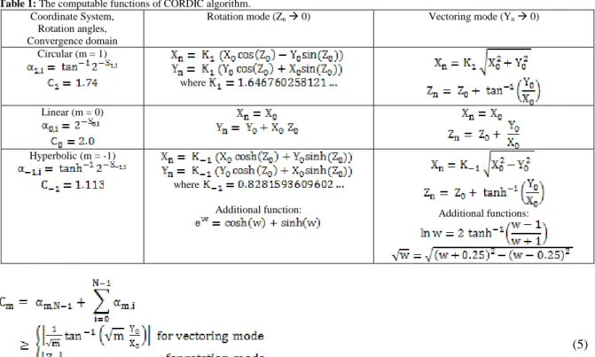
This algorithm can be implemented in two different modes which are the rotation and vectoring mode. Thus, during iteration process, it drives the Z value towards zero in rotation mode while it drives the Y value towards zero in vectoring mode. Therefore, the computable functions of this algorithm according to its coordinate system and modes are summarized in Table 1.
Table 1: The computable functions of CORDIC algorithm. Coordinate System,
Rotation angles, Convergence domain
Rotation mode (Zn 0) Vectoring mode (Yn 0)
Circular (m = 1)
where Linear (m = 0)
Hyperbolic (m = -1)
where
Additional function: Additional functions:
(5)
Previously, there are several researches (Metafas and Goutis, 1991;Vladimirova et al., 2003; Zhou et al., 2008; Madian and Aljarhi, 2013) were being carried out for the implementation of floating-point CORDIC processor. However, most of the researchers implement the CORDIC processor using FPGA but did not introduce the RISC based architecture on their processor. Therefore, this paper proposed a new architecture of floating-point CORDIC processor using RISC to perform the computation operations by instruction.
Methodology:
The processor design was started by designing the floating-point CORDIC arithmetic unit as shown in Fig. 1 that employed with hybrid rotation angle method and unified division-free argument reduction algorithm. After that, the arithmetic unit was integrated into the RISC architecture. Then, the instruction set format was properly designed in 16-bits which include the opcode and operand to perform several processing operations such as load, store, branching, jump and CORDIC computation operations. Thus, the datapath of the RISC architecture consists of instruction memory (IM), program counter (PC), instruction register (IR), register file (RF), data memory (DM) and CORDIC arithmetic unit as shown in Fig. 9. Meanwhile, a controller was then designed to control the initialization process and also the instructions fetch, decode and execute operations. Thus, all the designs were coded in System Verilog HDL. Therefore, the detail descriptions for the design process are discussed in the following subsections.
A. Hybrid-mode Floating-point CORDIC Arithmetic Unit:
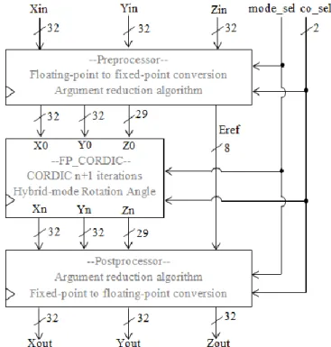
Generally, this unit is the most important arithmetic core inside the processor to execute the single precision floating-point arithmetic computations using CORDIC algorithm. Thus, this unit was developed in three modules as described below and its functional block diagram as shown in Fig. 1.
(a) Preprocessor which transforms the input data of X, Y and Z from 32-bit single precision floating-point IEEE754 format into a suitable width of internal fixed-point format which fulfil the accuracy requirement. The compensation for the scaling factor, Km on the input X and Y are performed in this block. Apart from that, it also employs the unified division-free argument reduction algorithm for the argument data to expand its convergence range.
(b) CORDIC iteration core which uses all the internal fixed-point data retrieved from the output of the preprocessing part to execute the CORDIC iterations in order to evaluate certain computable elementary functions from Table 1. Apart from that, it also employs the hybrid-mode rotation angle method to reduce the hardware resources needed at the same time to minimise the hardware cost.
Fig. 1: The overall functional block diagram of the hybrid-mode floating-point CORDIC arithmetic unit.
1) Internal Fixed-point Data Format:
The 32-bit single precision floating-point input data of X0, Y0 and Z0 are converted into respective internal fixed-point format by the preprocessor with suitable numbers of overflow and guard bits as introduced by Rix et al. (1992) prior to the CORDIC calculation phase as shown in Fig. 2 and Fig. 3.
31 30 28 27 5 4 0
s overflow bits Mantissa guard bits
Fig. 2: 32-bits internal fixed-point format for X and Y.
28 27 26 25 3 2 0
s overflow bits Mantissa guard bits
Fig. 3: 29-bits internal fixed-point format for Z.
2) Argument Reduction Algorithm:
A unified division-free argument reduction algorithm developed by Hahn et al. (1994) was employed in the CORDIC arithmetic unit to expand the convergence of the input argument. Basically, this algorithm depends on the coordinate system of the CORDIC algorithm since the maximum convergence domains for each coordinate system are different. Also, it also depends on the mode of CORDIC algorithm since the functions to be evaluated for each mode in each coordinate system are different.
Assume that the floating-point input data are represented by the following equations:
(6)
(7)
(8)
where S = sign, E=exponent, and M=mantissa
Then, the reference exponent is denoted by Eref and its corresponding values for each coordinate system and mode are evaluated as shown in Table 2.
Table 2: Evaluation of Reference Exponent.
Coordinate System Rotation mode Vectoring mode
Apart from that, the floating-point inputs of X0, Y0 and Z0 are converted into respective internal fixed-point format. Thus, the fixed-point formats of X0, Y0 and Z0 are expressed by , and as shown below:
(9)
(10)
(11)
Thus, the algorithms for each coordinate system and mode are described below: (i) Linear coordinate (m=0)
In this coordinate, no real argument reduction is needed but some adjustments can be made as shown in Table 3 to perform multiplication and division operations.
Table 3: Multiplication and division operations in linear mode. Rotation mode
(multiplication operation)
Vectoring mode (division operation)
Set Y0 = 0 Set Z0 = 0
Eref = Ex0 + Ez0 Eref = Ey0 – Ex0
Myn = Mx0” Mz0” Mzn = My0/Mx0
Yn = Sx0 Sz0 norm(Myn 2Eref) Zn = Sx0 Sy0 norm(Mzn 2Eref) (ii) Circular coordinate (m=1)
(a) For rotation mode
The input argument, Z0 was mapped into the domain of [0, ] by using the property of periodicity as shown below:
(12)
where
D = the mapped argument in domain of [0, ]
Q = the integer value denoting the quadrant of the argument Z (represented by the integer part of fixed-point format)
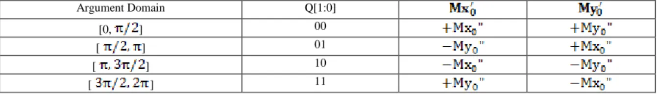
Table 4: The modifications on Mx0” and My0” for different quadrants.
Argument Domain Q[1:0]
[0, ] 00
[ ] 01
[ ] 10
[ ] 11
Meanwhile, the input values of and need to be modified to and as tabulated in Table 4 according to their corresponding two least significant bits of Q. After that, , and are treated as the inputs for the CORDIC iteration core unit to perform iterative computation. Finally, the outputs are and while approach to zero. Thus, these two outputs, and are sent to the postprocessor in order to obtain two normalized floating-point outputs as shown below:
(13)
(14)
(b) For vectoring mode
Unlike rotation mode, the input values of , and do not need any modification, so can directly treated as the inputs for the CORDIC iteration arithmetic unit and the output are and while approach to zero. Then, and are sent to the postprocessor in order to obtain two normalized floating-point outputs as shown below:
(15)
(16)
where
(a) For rotation mode
The input argument, Z0 was mapped into the domain of [0, ln(2)] by using the property of periodicity as shown below:
(17)
where
D = the mapped argument in domain of [0, ln(2)]
Q = the integer value denoting the quadrant of the argument Z (represented by the integer part of fixed-point format)
Meanwhile, the input values of and need to be modified to be and as shown below:
(18)
(19)
After that, , and are treated as the inputs for the CORDIC iteration arithmetic unit to perform iterative computation. Finally, the outputs are and while approach to zero. Thus, these two outputs, and are sent to the postprocessor in order to obtain two normalized floating-point outputs as shown below:
(20)
(21)
where
and (b) For vectoring mode
In this mode, the input data of and are being processed differently in two intervals of input argument by the preprocessor as shown below:
(i) Interval I:
In this interval, the input values of , and do not need any modification, so can directly treated as the inputs for the CORDIC iteration arithmetic unit and the output are and while approach to zero. Then, and are sent to the postprocessor in order to obtain two normalized floating-point outputs as shown below:
(22)
(23)
(ii) Interval II:
In this interval, the input values of and need to be modified to and as shown in the following equations:
(24)
(25)
where Enew is the new exponent value obtained from the functions of in normalized
form where .
After that, , and are treated as the inputs for the CORDIC iteration core unit and the outputs are and while approach to zero. Then, and are sent to the postprocessor in order to obtain two normalized floating-point outputs as shown below:
(26)
(27)
where
3) Hybrid Rotation Angle Method:
The hybrid rotation angle method introduced by Shaoyun et al. (1997) was employed in the CORDIC arithmetic unit to reduce the hardware cost and resources used. In this method, the angles are represented by different equation in two intervals. Thus, for the CORDIC arithmetic unit that rotates n times, the rotation angles for the first n/3 rotation sequences must satisfy the equation (4) and the angles are retrieved from the look-up table memory. Meanwhile, for the remaining 2n/3 rotation sequence, the rotation angle can be approximated from the equation of so the angles can be retrieved directly from the shifted value of the rotation angle of the first iteration in linear mode. Therefore, it can reduce the hardware resources for the lookup table memory since only the rotation angles for the first n/3 rotation sequence are stored.
B. Instruction Set Architecture (ISA):
The ISA is also a programmer’s model which specifies the choice of programming model, number of destination of registers and addressing modes (Khalil, 2013). Thus, it should include the instruction set and format, the machine’s memory, the programmer-accessible registers, and various processor registers such as the followings (Khalil, 2013):
(a) Program counter (PC), contains the address of next instruction.
(b) Instruction register (IR), holds temporarily the current instruction that being fetched.
(c) Memory address register (MAR), holds the address of the memory location for the data in MDR.
(d) Memory data register (MDR), holds and buffers the data that want to be stored inside memory. (e) Accumulator (AC), holds data temporarily for processing.
Furthermore, the instruction set must include all the important instructions to perform its required tasks and it also should be orthogonal in which the same instructions are not repeated or overlapped in order to achieve optimum hardware cost. Meanwhile, to design a RISC processor, it should include fixed instruction length, simplified decoding logic, few addressing modes, simple instructions, only load and store instructions have access to memory and large register file.
Thus, the ISA specification for the proposed processor is described below:
(a) The design’s datapath consists of a 12-bits program counter (PC), 16-bits instruction register (IR), (4096 x 16) instruction memory block (IM), (8 x 32) register file array block (RF), and (512 x 32) data memory block (DM).
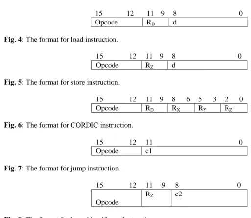
(b) The instruction set and formats are shown below:
15 12 11 9 8 0
Opcode RD d
Fig. 4: The format for load instruction.
15 12 11 9 8 0
Opcode RZ d
Fig. 5: The format for store instruction.
15 12 11 9 8 6 5 3 2 0
Opcode RD RX RY RZ
Fig. 6: The format for CORDIC instruction.
15 12 11 0
Opcode c1
Fig. 7: The format for jump instruction.
15 12 11 9 8 0
Opcode
RZ c2
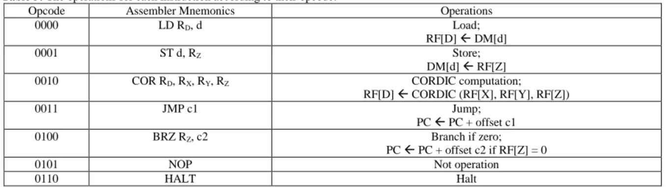
Table 5: The operations for each instruction according to their opcode.
Opcode Assembler Mnemonics Operations
0000 LD RD, d Load;
RF[D] DM[d]
0001 ST d, RZ Store;
DM[d] RF[Z]
0010 COR RD, RX, RY, RZ CORDIC computation;
RF[D] CORDIC (RF[X], RF[Y], RF[Z])
0011 JMP c1 Jump;
PC PC + offset c1
0100 BRZ RZ, c2 Branch if zero;
PC PC + offset c2 if RF[Z] = 0
0101 NOP Not operation
0110 HALT Halt
C. RTL Design of the Processor:
By RTL design approach, the processor design is partitioned into two separate units which are datapath unit (DU) and control unit (CU). Thus, the DU consists of three main parts which are the storage or registers part, the bussing and steering logic part and the processing and computation part. Meanwhile, the CU determine the sequence of data-processing operations performed by DU via a finite state machine (FSM).
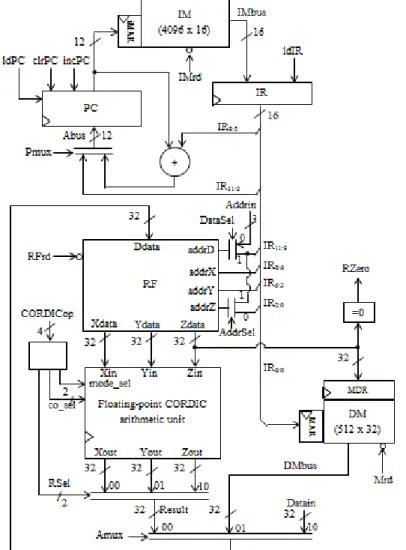
1) The datapath unit (DU):
Based on the ISA specification as described earlier, the DU that consists of PC, IR, IM, RF, DM, and CORDIC arithmetic unit was constructed as shown in Fig. 9. Thus, the CORDICop signal is an external signal that needs to be introduced or set to select the mode, coordinate system and the final output result from Xout, Yout and Zout for different CORDIC functions as tabulated in Table 6.
Table 6: Different CORDIC functions represented by CORDICop signal. CORDICop signal
value
Computed CORDIC functions
mode_sel 0: rotation 1: vectoring
co_sel 00: Linear 01: Circular 10: Hyperbolic
RSel 00: Xout 01: Yout 10: Zout
0000 cos(z) 0 01 00
0001 sin(z) 0 01 01
0010 cosh(z) 0 10 00
0011 sinh(z) 0 10 01
0100 sqrt(x2+y2) 1 01 00
0101 atan(y/x) 1 01 10
0110 sqrt(x2-y2) 1 10 00
0111 atanh(y/x) 1 10 10
1000 0.5*ln(w) 1 10 10
1001 ez 0 10 00
1010 x*z 0 00 01
1011 y/x 1 00 10
2) The control unit (CU):
Firstly, RTL code was derived based on the processor execution flow. In the initialization state (INIT), the processor is executed in writing data mode in which the input data was written into register file in specific address before the start signal is asserted to ensure that the processor has valid data to be processed in the CORDIC arithmetic unit after start signal is asserted. Thus, after the start signal is asserted, the processor performs the fetch-decode-execute loop continuously. Thus, a RTL-CS table was built based on the RTL code to obtain the control vectors for each state which include all the control signals to control the micro-operations of the DU as shown in Table 7. Finally, the CU was designed using Mealy FSM to control the processor’s operations for each state sequentially.
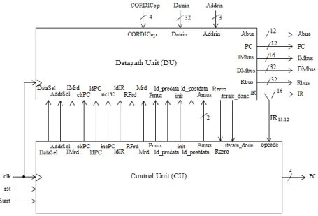
3) Integration of DU and CU:
After completed the design of DU and CU, these two units are integrated to obtain the top-level functional block diagram of the processor as shown in Fig. 10.
Result and Analysis:
1) Verification of CORDIC instruction (COR):
To perform the CORDIC computation, the valid input data of X, Y and Z must be available inside the processor either in the data memory or in the register files before the start signal is asserted. Then, the CORDIC computation instruction (COR) is fetched and decoded once the start signal is asserted to perform CORDIC calculation and generate the output results that stored inside the register file. Thus, the simulation results are then compared with the results calculated by scientific calculator as shown in Table 8 in order to verify the results and also analyze its accuracy by referring to their absolute differences.
Fig. 9: The functional block diagram of DU for the proposed processor based on RISC architecture.
Table 7: The control vectors for each state in the processor.
Control vector, CV={DataSel, AddrSel, IMrd, clrPC, ldPC, incPC, ldIR, RFrd, Mrd, Pmux, ld_predata, init, ld_postdata, Amux[1], Amux[0]}
State State name CV (in binary) CV (in hex)
0000 INIT 001000000001010 100A
0001 FCH 101100010001000 5888
0010 DEC 101101110001000 5B88
0011 LD1 101100001001000 5848
0100 LD2 101100001001001 5849
0101 ST 111100010001000 7888
0110 COR1 101100010001000 5888
0111 COR2 101100010011000 5898
1000 COR3 101100010001000 5888
1001 COR4 101100010000000 5880
1010 COR5 101100000000100 5804
1011 JMP 101110010101000 5CA8
1100 BRZ1 111100010001000 7888
1101 BRZ2 111110010001000 7C88
1110 NOP 101100010001000 5888
Fig. 10: The completed functional block diagram of the proposed processor.
Table 8: The simulation results of the proposed processor and scientific calculator results for each computable function. CORDICop and its
operation and initialization
Inputs Proposed
Processor Results, RP Scientific Calculator Results, RC Absolute difference,
X Y Z
0000; Compute cos(Z)
Set X=1, Y=0
1 0 0.7853982 0.7071034 0.7071067812 0.000003381
1 0 1.745329252 -0.17364731 -0.1736481777 0.000000867
1 0 3.8397243 -0.7660408 -0.7660444431 0.000003643
1 0 5.7595863 0.8660211 0.8660254038 0.000004303
0001; Compute sin(Z)
Set X=1, Y=0
1 0 0.7853982 0.70710325 0.7071067812 0.000003531
1 0 1.745329252 0.9848029 0.984807753 0.000004853
1 0 3.8397243 -0.64278436 -0.6427876097 0.000003249
1 0 5.7595863 -0.49999768 -0.5 0.000002320
0010; Compute cosh(Z)
Set X=1, Y=0
1 0 0.5 1.1276767 1.127625965 0.000050735
1 0 0.96 1.4972413 1.49729468 0.000053380
1 0 1.5 2.352509 2.352409615 0.000099385
1 0 2.3 5.036936 5.03720649 0.000270490
0011; Compute sinh(Z)
Set X=1, Y=0
1 0 0.5 0.52120507 0.5210953055 0.000109764
1 0 0.96 1.1143299 1.114401794 0.000071894
1 0 1.5 2.1293893 2.129279455 0.000109845
1 0 2.3 4.936671 4.936961806 0.000290806
0100; Compute sqrt(x2+y2)
Set Z=0
1.2 2.4 0 2.6832814 2.683281573 0.000000173
2.4 4.8 0 5.366563 5.3665663146 0.000003314
4.8 9.6 0 10.733126 10.73312629 0.000000290
9.6 19.2 0 21.466251 21.466252258 0.000001742
0101; Compute atan(Y/X)
Set Z=0
1 0.5 0 0.4636477 0.463647609 0.000000091
1 8.5 0 1.4536877 1.453687582 0.000000118
1 19.5 0 1.519559 1.519559159 0.000000159
1 178.5 0 1.565194 1.565194145 0.000000145
0110; Compute sqrt(W)
Set X=W+0.25, Y=W-0.25, Z=0
0.75 0.25 0 0.7071067 0.7071067812 0.000000081
1.5 1 0 1.1180338 1.118033989 0.000000189
3.25 2.75 0 1.7320508 1.732050808 0.000000008
4.25 3.75 0 2.0000002 2 0.000000200
0111; Compute atanh(Y/X)
Set Z=0
1 0.2 0 0.20276292 0.2027325541 0.000030365
1 0.5 0 0.54927254 0.5493061443 0.000033604
1 0.78 0 1.0453386 1.045370548 0.000031948
1 0.95 0 1.8317597 1.831780823 0.000021123
1000; Compute 0.5*ln(W) Set X=W+1, Y=W-1,
Z=0
1.5 -0.5 0 -0.3465484 -0.3465735903 0.000025190
3.8 1.8 0 0.51480347 0.5148097086 0.000006238
2.6 0.6 0 0.23495902 0.2350018146 0.000042794
1.2 -0.8 0 -0.8046593 -0.8047189562 0.000029656
1001; Compute exp(Z)
Set X=1, Y=1
1 1 0 1.0000292 1 0.000029200
1 1 0.98 2.664276 2.664456242 0.000180242
1 1 1.82 6.1725283 6.17185845 0.000669850
1 1 2 7.3898187 7.389056099 0.000762601
1010; Compute X*Z
Set Y=0
0.5 0 1.5 0.75 0.75 0.000000000
2.1 0 1.88 3.947997 3.948 0.000003000
2.3 0 -0.78 -1.7939998 -1.794 0.000000200 1011;
Compute Y/X Set Z=0
1 2.4 0 2.4 2.4 0.000000000
4.38 0.96 0 0.21917807 0.2191780822 0.000000012
3.67 -7.3 0 -1.9891007 -1.989100817 0.000000117
271.56 -672.88 0 -2.4778316 -2.477831787 0.000000187
As shown in Table 8, in overall, the simulation results are almost the same as the scientific calculator results. Therefore, by referring to absolute difference values, the proposed processor generally achieves more than four decimal places of accuracy except for some hyperbolic functions. This is due to the larger rounding error during argument reduction process or scaling operation and also the larger approximation error in rotation angle for hyperbolic mode.
2) Verification of other instructions in the processor:
To verify the operations of other instructions such as load (LD), store (ST), jump (JMP), branch if zero (BRZ), not operation (NOP) and halt (HALT), specific instructions based on the instruction set format defined earlier are used to perform these operations. Thus, the following shows the simulation waveforms for these instructions.
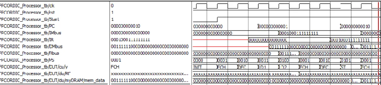
(a) Case 1: Load and store instructions (LD and ST)
Description: The data inside the data memory in address 0, i.e. 00111111000000000000000000000000 is loaded into register file (RF) in address 0. After that, the loaded data in RF in address 0 is stored back to data memory in address 512.
Fig. 11: The simulation waveform of load and store operations.
Fig. 12: The contents inside register file after load operation.
Fig. 13: The contents inside data RAM after store operation.
(b) Case 2: Jump instruction (JMP)
Description: The address of next instruction is jumped to 8 Tested instruction assembler code:
LD 0,0 ST 512,0
Fig. 14: The simulation waveform of jump operation.
(c) Case 3: Branch if zero instruction (BRZ)
Description: Increment the address of next instruction by 8 if the dataZ in address 0 is 0 where the Rzero is high.
Fig. 15: The simulation waveform of branch if zero operation.
(d) Case 3: Not operation and halt instructions (NOP and HALT)
Description: Not operation executed for one cycle and then the execution is halted or stopped.
Fig. 16: The simulation waveform of not operation and halt instructions.
Therefore, based on the simulation waveform obtained above, the executions of all the instructions for the proposed processor are correct and verified.
Conclusion:
In a nutshell, we successfully design a 32-bit hybrid-mode single precision floating-point CORDIC processor based on RISC architecture on FPGA and its functionality of each instruction is verified by the simulation waveforms and results. The design generally achieves acceptable accuracy. The approximation error of rotation angle and the rounding error during scaling or argument reduction process can affect the accuracy of the result. In our design, some of the basic useful instructions are defined in the instruction set such as load (LD), store (ST), CORDIC computation (COR), jump (JMP), branch if zero (BRZ), not operation (NOP) and halt (HALT). Thus, the CORDIC computation instruction (COR) can be used to solve various elementary functions such as trigonometry and hyperbolic functions, exponential, natural logarithm, square root as well as multiplication and division by setting different CORDICop signal value. For further works, double precision floating point format (64-bit) can be used to enhance the accuracy of the result in the CORDIC processor however it consume more hardware resources. Apart from that, the instruction set and architecture can be
Tested instruction assembler code: BRZ 0, 8
Tested instruction assembler code: NOP
modified so that the processor can be used for other advance applications that related to CORDIC algorithm such as matrix inversion, eigenvalue computation and so forth.
ACKNOWLEDGEMENT
The authors would like to acknowledge the Malaysian Ministry of Education and Universiti Teknologi Malaysia for the research grant (PRGS Vot number 4L611) and supports given.
REFERENCES
Hahn, H., D. Timmermann, B.J. Hosticka and B. Rix, 1994. A unified and division-free CORDIC argument reduction method with unlimited convergence domain including inverse hyperbolic functions. IEEE Transactions on Computers, 43(11): 1339-1344.
Hu, Y.H., 1992. The quantization effects of the CORDIC algorithm. IEEE Transactions on Signal Processing, 40(4): 834-844.
Khalil, M., 2013. RTL Design for FPGA with SystemVerilog. Universiti Teknologi Malaysia: Desktop Publisher.
Madian, A. and M. Aljarhi, 2013. A Multi Cordic Architecture on FPGA Platform. International Journal of Electrical, Electronic Science and Engineering, 7(12): 1264-1272.
Metafas, D.E., C.E. Goutis, 1991. A floating point pipeline CORDIC processor with extended operation set. IEEE International Sympoisumon Circuits and Systems, 5: 3066-3069.
Rix, B., D. Timmermann, H. Hahn and B.J. Hosticka, 1992. A Cordic-based Floating-point Arithmetic Unit. Custom Integrated Circuits Conference, Proceedings of the IEEE 1992, 30.3.1-30.3.4.
Shaoyun, W., V. Piuri, E.E. Wartzlander, Jr., 1997. Hybrid CORDIC algorithms. IEEE Transactions on Computers, 46(11): 1202-1207.
Vladimirova, T., D. Earney, S. Keller and Prof. M. Sir Sweeting, 2003. Floating-Point Mathematical Co-Processor for a Single-Chip On-Board Computer. Proceedings of the 6th Military and Aerospace Programmable Logic Devices International Conference 2003 (MAPLD'03), Paper D5.
Volder, J.E., 1959. The CORDIC trigonometric computing technique. IRE Transactions Electronic Computers, EC-8(3): 330-334.
Walther, J.S., 1971. A unified algorithm for elementary functions. AFIPS Spring Joint Computer Conference, 38: 379-385.