Abstract - This document presents the construction of a light dimmer circuit that utilizes the current-regulating properties of a triac. Prior to being triggered, the triac provides a barrier in the circuit, preventing current flow from a 70V AC source through the light bulb. During this time voltage across a capacitor within in the circuit builds up until it exceeds the breakover voltage of a diac. Once the breakover voltage is exceeded, the diac “fires” the triac into a conducting state and current flows through the light bulb. The amount of voltage seen over the light bulb is determined by the firing angle of the triac which is set by the RC time constant of the circuit. This process then repeats every half cycle. Finally, it can be seen that this switching introduces high order harmonics into the system.
I. INTRODUCTION
his document presents the construction, operation, and testing of a light dimmer circuit. Using simple devices such as a diac and a triac, power flow is regulated to a light bulb by intermittently applying a 70V AC source across the load during each half cycle. The intensity of the light is determined by the proportion of the sine wave that is applied across the load. This document contains the circuit operation, testing results, and the observations that were made during the experiment.
II. LIGHT DIMMER CIRCUIT OPERATIONS
Figure 1 shows the construction of the light dimmer circuit with the triac. The circuit is designed such that only a portion of the 60Hz sine wave from the Variac passes through the light bulb. To accomplish this, a bilateral diac is used to control the current flow to the triac. Initially the capacitor is discharged, and during each half cycle of the input from the Variac, Van, the capacitor is charged to its breakover voltage. When this occurs the diac begins to conduct and discharges the capacitor through the triac gate. This point in time is known as firing and it allows the voltage on Van to be applied to the light bulb. For most of this experiment the Variac was set to 70V AC.
Figure 1: Light dimmer circuit with triac
The intensity of the light is controlled by varying the firing angle for the circuit. This is accomplished by controlling the rate at which the capacitor charges, and is determined by the RC time constant of the series potentiometer and capacitor. In Figure 1, the time constant can be seen as the 3.3k ohm resistor plus the value of the potentiometer times the 0.1uF capacitance. Thus, to control the intensity of the light, one simply controls the value of the resistance on the potentiometer, which determines the rate at which the capacitor reaches the breakover voltage. The smaller the RC time constant, the quicker the capacitor reaches the breakover voltage, and thus the more of the 60Hz sine wave that is applied over the light bulb. The greatest intensity of the light can be seen when the resistance of the potentiometer is set to zero, and the greatest potion of the sine wave is applied over the bulb.
Initially, before the diac conducts, the triac is in a non-conducting state. In this configuration, the circuit appears as in Figure 2 below. As one can see, there is no conduction through the light bulb, and thus the light remains off. (Notice that the small amount of current through the 3.3k ohm resistor is minimal and thus ignored here.)
Figure 2: Before firing - Triac non-conducting
Once firing occurs, the triac is in its conducting state, and
EE362L, Power Electronics
Triac Light Dimmer
Rochelle Stortz and Brian Taraba, Team 277 2/2/05
appears as a closed switch. As shown in Figure 3, this then causes the voltage, Van, to appear across the light bulb.
Figure 3: After firing - Triac conducting
It should be noted that, the quick change between conducting and non-conducting states of the triac, goes unnoticed by the human eye. Because the voltage on the source is 60Hz, the eye cannot detect the change of states, and thus one cannot see the light flickering on and off.
III. RESULTS
To ensure the safety of ourselves and those around us, all experiments were performed using an isolation transformer between the wall outlet and the Variac.
For the first part of the experiment, the potentiometer was set for full brightness, or minimum resistance. As discussed earlier, this corresponds to a minimum RC time constant, and thus allows the greatest portion of the input wave to be seen across the bulb. At this point the minimum firing angle, α, could be determined. A plot of Vab vs time can be seen in Figure 4 below.
Figure 4: Minimum Firing Angle
To determine the firing angle in degrees, it was first measured in milliseconds using the oscilloscope along with the period of the wave. Then, using equation 1, the firing angle in degrees was found. In this equation toff is the firing angle in milliseconds and α is the firing angle in degrees.
) 1 ( 360o × = period off
T
t
αUsing the above equation, the firing angle was found to be 28.1 degrees with toff = 1.3ms and Tperiod = 16.65ms. The voltage across the light bulb, Vab,rms, was measured with an
oscilloscope to be 68.9Vrms and with a multimeter to be 65.7Vrms.
Next, the potentiometer was set so that the firing angle was approximately equal to 90˚. This trace is shown in Figure 5. In this position, again using the oscilloscope and equation 1, the voltage across the light as well as the firing angle were determined. The measured values were found to be toff = 4.16ms, Tperiod = 16.65ms, Vab,rms (multimeter) = 41.6V, and Vab,rms (oscilloscope) = 50.07Vrms. Since the circuit is energized with Van = 70Vrms, the theoretical voltage for
α=90° is
2
70V = 49Vrms. This is very close to our measured
value with the oscilloscope. However, the multimeter reading was significantly less than this voltage. This discrepancy will be discussed in the observation section of this report.
Figure 5: Firing angle of 90°
Next, the potentiometer was set such that the circuit barely had conduction. At this point the largest firing angle was obtained (Figure 6). Measurements taken with the
oscilloscope gave toff = 6.7ms, Tperiod = 16.65ms, Vab,rms (multimeter) = 6.7Vrms, and Vab,rms (oscilloscope) = 14.9Vrms. Again, using equation 1, the firing angle, α, was determined to be 144.9°. It should be noted that beyond this firing angle, the capacitor will never reach its breakover voltage before discharging during the negative half cycle of the input, and thus the circuit will never conduct. Again, the discrepancy between the oscilloscope and the multimeter measurements will be discussed in the following section.
Figure 6: Firing angle = 145°
For the fourth part of the experiment, both the capacitor voltage, Vcn, and the source voltage, Van, were observed on the oscilloscope (Figure 7). Notice that one can see the capacitor charging up to the point where the breakover voltage is reached, and then a quick discharge is observed through the gate of the triac. In this plot the peak to peak voltage of Vcn was found to equal 66V which indicates the breakover voltage of our diac to be equal to 33V. Also toff was measured to equal 4.1ms and Tperiod was equal to 16.65ms, thus α = 88.6˚.
Figure 7: Van and Vcn for α = 90°
Beyond the maximum firing angle of 145°, we once again observed the capacitor voltage Vcn, and the sourceVan. In this
configuration, the capacitor never reaches the breakover voltage, and thus the capacitor voltage has a steady-state phasor solution (2) related to the source Van. As the resistance
of the potentiometer increases the capacitor voltage decreases in value.
)
2
(
1
1
1
1
+
=
+
=
RC
j
V
C
j
R
C
j
V
V
cn an anω
ω
ω
The final step of the lab was to examine the harmonic components that are introduced into the light bulb voltage as a result of the switching that occurs in the circuit. With Van again set to 70Vrms and the firing angle set to 90°, we positioned the probe to measure Vab. Using the oscilloscope, the Fast Fourier Transform (FFT) of the voltage signal was found. This FFT is shown below in Figure 8.
Figure 8: FFT of Vab at α = 90˚
The dB level of the fundamental frequency, 60Hz, was measured have a peak of 33.75dB, while the third harmonic, 180Hz, peak was measured to be 26.56 dB. Recall that the half wave symmetry of this waveform lends itself to only odd order harmonics. The source for this circuit was a 70Vrms sine wave. Through the FFT definition for a sine wave, the fundamental frequency should peak at 41.5Vrms or 32.3dB. This is very close to the the value that we measured in our experiment.
IV. OBSERVATIONS
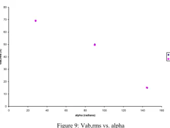
During this experiment several observations were made. First, Excel was used to plot three oscilloscope-measured Va,rms data points from the experiments above vs. α, along with the value of Vab,rms determined from equation 3 below (α in radians). This plot can be seen in Figure 9.
∏
+
∏
−
=
2
2
sin
1
,
,
2 2ab
rms
V
an
rms
α
α
V
(3)
Vab,rms vs. alpha 0 10 20 30 40 50 60 70 80 0 20 40 60 80 100 120 140 160 alpha (radians) Vab ,r m s ( V ) Observed Calculated
Figure 9: Vab,rms vs. alpha
Notice that our observed values closely match those predicted by the theoretical formula.
Secondly, it was noticed that the RMS voltage levels measured with the multimeter were not in agreement with those observed using the oscilloscope. It was determined that this discrepancy is caused by the multimeters’ tendency to average the rectified wave and make a sinewave assumption. It is for this reason that as the firing angle was increased, and the voltage across the light deviated further and further from a true sine wave, that the multimeter reading became less and less accurate.
Also, during the fourth part of our experiment, we found that the variation of the capacitor voltage, Vcn, with respect to the input voltage, Van, closely followed the predicted behavior by the Excel program given with this experiment, EE362L_Triac_Light_Dimmer.xls. We found that the only difference between our observations and the Excel predictions were during the discharging of the capacitor through the triac gate. The oscilloscope printout shows the capacitor discharging more clearly than the Excel program does. However beyond the maximum firing angle, we found that the oscilloscope plots closely matched those predicted by the phasor solution and the Excel program.
During the last portion of the lab, an oscilloscope was used to measure the amplitude of the higher order harmonics. As shown in Figure 8 and through calculations shown below (4), it was determined that the higher order harmonics have greater amplitudes than are typically desired in power systems. These high amplitudes create noise within the circuit, and in worst cases even audible noise can be present when the harmonic components fall within the RF band. For our circuit, we found the amplitude of the third harmonic to be 0.437 times the amplitude of the fundamental. This ratio compares quite favorably to the predicted value that was calculated in the Microsoft Excel file, EE362L_Triac_Light_Dimmer_ Fourier_Waveform.xls. The anticipated ratio was found to be 0.537, so we can concur that the physical working model that we built performs at a higher level than the Fourier Analysis
approximated.
.
56
.
26
75
.
33
,
8
V
60dB
and
V
180dB
Figure
From
Hz=
Hz=
Converting from dB to Vrms (4) rms rms Hz rms Hz V V V thus V V dB , 1 10 48.7 1 log 20 75 . 33 20 75 . 33 60 60 10 = • = = rms rms Hz rms Hz thusV V V V V dB , 1 10 21.3 1 log 20 56 . 26 20 56 . 26 180 180 10 = • = = dB V V180Hz − 60Hz =−7.19 437 . 0 10 1 , 1 log 20 19 . 7 20 19 . 7 60 180 60 180 10 = • = ÷ − = − − rms Hz Hz rms Hz Hz V V V thus V V V dB 437 . 0 7 . 48 3 . 21 , Vrms ÷ Vrms = verify To V. CONCLUSIONWe have successfully demonstrated the operation of the triac light dimmer circuit. With this circuit we have shown that one can regulate the intensity of a light using an AC wall outlet as a source, and varying the RC time constant used to determine the point in time that the triac conducts the AC wave through the light during each half cycle. In addition we have demonstrated the concept of a firing angle, α, and its relation to the RMS voltage applied to the light bulb. The one main drawback of this circuit is the vast amount of harmonics that are present in the system, however for its simplicity, the design is quite impressive.
VI. WORK DISTRIBUTION
Stortz Taraba
Circuit Construction 50% 50%
Circuit Test 50% 50%
Report 50% 50%
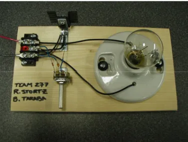
Figure 10: Our Light Dimmer Circuit