DIY Incubator
A Senior Project presented to
the Faculty of the Biomedical Engineering Department California Polytechnic State University – San Luis Obispo
In Partial Fulfillment
of the Requirements for the Degree Bachelors of Science
By
Aryan Zia, Grace Spurlock, and Garrett Janney
Table of Contents
Executive Summary 2
Statement of Work 2
Indications for Use 8
Customer Requirements 8
Specification Development 8
Budget 9
Total Available Market (TAM) 11
Competitive Advantage 12
Intellectual Property Assessment 13
Conjoint Analysis 13
Morphology 15
Concept Evaluation 20
Conceptual Model 21
Detailed Design 23
Final Design Dimensioning 26
Material Selection 26
Cost Estimation 27
Prototype Manufacturing Plans 28
Manufacturing Process Instructions (MPI) for Structural Components 28 Manufacturing Process Instructions (MPI) for Electrical Components 36
Bill of Materials 49
Test Plans 50
Testing Data and Analysis 59
Discussion 69
Conclusions 70
References 74
Executive Summary
This project report provides detailed information on designing and building a DIY Incubator. The device is indicated for growing and maintaining BSL-1 mammalian or bacterial cell culture with a temperature control in the range of 25-45°C ± 1°C. The device is made fully
programmable via an Arduino, and is structurally designed to fit two T75 cell culture flasks at a time. The device is able to return to a specified temperature set point within 10 minutes and maintains 5% CO2 partial pressure conditions. The incubator has a small physical footprint, with an overall dimension of 22in x 16in x 15.5in (LxWxH). The system is intended to be used in a university laboratory by students and researchers. After manufacturing and testing the system, all specifications were met except for the specification of 5% ± 0.25% CO2 control. Our CO2 system set up has promising useability, but requires revisions and additional testing to meet its desired specification. This report will go into detail on the results of the tests that passed and why its specification was not met during testing, as well as future recommendations for this system. We are confident this device will have useful implications for cell cultivation research labs on campus.
Statement of Work
Executive AbstractThis Statement of Work covers the design and manufacturing of the DIY Incubator. This project aims to provide a low-cost incubator with a small physical footprint capable of sustaining bacterial and mammalian cell cultures. The total estimated cost of this project is $700 with an estimated time of completion of 6 months.
Introduction
The DIY Incubator project is sponsored by Dr. Ben Hawkins, professor of Electrical Engineering (EE) and Biomedical Engineering (BMED) at Cal Poly, San Luis Obispo. Undergraduate BMED students: Aryan Zia, Grace Spurlock, and Garrett Janney will create the design and physical prototype based on the requirements described by the sponsor. The background will provide more detail about the project and why there is a need for a low-cost incubator.
Background
Mammalian cells are very sensitive to the culture environment, and it is important to maintain stable culture conditions. Water-jacketed incubators equipped with CO2 pressure control are widely used for maintaining an optimal culture environment in terms of gas phase, temperature, and humidity [3]. Typical incubators are large and heavy because they accommodate various tissue culture methods. There is truly a need for new incubator designs, capable of growing cell cultures in a small physical footprint. An important factor for our DIY Incubator is to fully identify the needs for the type of cell culture that our sponsor wants to use the incubator for. In addition, we must also consider the vessel type (plates, flasks, bottles, and dishes are all available for cell culture applications, [5]). This may seem counterintuitive, however it’s vital we provide optimal conditions for the specific cell type, in order to meet appropriate specifications. After our first meeting, it was agreed with the sponsor that we would be using T75 flasks and BSL-1 mammalian cell cultures. The technical challenges lie in formulating a good design that meets all the requirements, since the incubator should be capable of holding 2 of these flask types at a time, and keeping a small physical footprint with the dimension specs that were agreed on.
Current incubators on the market also provide a range of additional features, such as a
shaker/rocker element which allows for mixing, blending, or agitating of substances in a tube or flask. With the standard of technical features and quality control systems in current products, incubators that have a small footprint and a low-cost are rare to find. In fact, purchasing a high end incubator from a biotech manufacturer could cost upwards of $7,000 [1]. The DIY Incubator project aims to solve these problems and to develop an open-source platform for public use. Our goal is to create a low-cost, temperature-controlled DIY Incubator that is an optimal size for various Cal Poly BMED lab spaces.
We searched for existing patents on current incubators to see what competitors on the market are up to. This helped formulate concept ideas for our own designs, while avoiding ways to avoid infringement. Refer to Appendix AII, for the USPTO patents we considered to have similarities to our incubator design. We also conducted research on the FDA website in order to determine classification of devices and applicable industry standards and regulations. It should be noted that the project team intends to follow strict guidelines and regulations for FDA approval. The FDA has previously classified incubators for microbiology use as a Class I device [4]. We agree with this classification considering the invasiveness and duration of our device and intend to follow through with protocols dictating Class I design. ISO standards 9001 and 13485 for quality management and medical device efficacy will be implemented.
Objectives
temperature accuracy measure, and a small footprint. These three constraints are explicitly included in the DIY Incubator project. Additional design elements such as a CO2 partial pressure control and an orbital shaking feature are not included in the scope of the project but may be implemented in the event of excess time and resources. Refer to Appendix AI for a detailed and quantified list of customer wants and needs.
Quality Function Deployment (QFD) is a process used to convert customer needs into
engineering specifications. We compiled our sponsor input and via the QFD method were able to identify the following critical specifications for the DIY Incubator: temperature control,
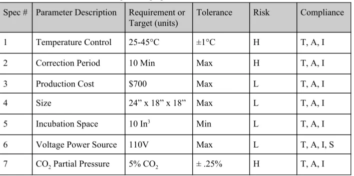
production cost, size, and voltage power source. The product specification matrix is presented in Table 1. The matrix lists specifications as well as quantifiable parameters, tolerances, initial associated risk assessments, and future compliance measures. For clarification, the risk column conveys how likely we are to fail at achieving the specification goal, rated on a scale of low (L), medium (M), or high (H). The compliance column conveys how we will determine whether or not the specification goal is met via methods such as testing (T), analysis (A), inspection (I), and/or similarity (S) to another product.
Table 1: Engineering Specifications for DIY Incubator Spec # Parameter Description Requirement or
Target (units)
Tolerance Risk Compliance
1 Temperature Control 25-45°C ±1°C H T, A, I
2 Correction Period 10 Min Max H T, A, I
3 Production Cost $700 Max L T, A, I
4 Size 24” x 18” x 18” Max L T, A, I
5 Incubation Space 10 In3 Min L T, A, I
6 Voltage Power Source 110V Max L T, A, I, S
7 CO2 Partial Pressure 5% CO2 ± .25% H T, A, I
For each specification we intend to carry out the following to ensure the specification is successful:
critical aspect of the product and has a high risk factor, we intend to implement three measures of compliance via testing, analysis, and inspection.
● Any fluctuation in temperature beyond ± 1°C from the set temperature is corrected within 10 minutes. This is a high risk specification because if temperatures deviate from the set temperature for too long of a period rates of cellular proliferation can decrease
drastically. Because of the negative effect fluctuations in temperature can have on the efficiency of cell cultivation, we consider this a high risk and intend to implement three measures of compliance via testing, analysis, and inspection.
● Production Cost: After planning our budget and using the most cost effective materials and electrical components, our estimated maximum total cost was $698.84. We consider cost to be a low risk because our total budget with the Hannah Forbes grant will give us adequate resources for testing or replacement of parts damaged during development of our functional prototype.
● Size: The size of the incubator is an important parameter as it should be versatile in being used at different BMED labs, and not utilizing a lot of space. We consider this a low risk factor, as we are going to design and build our incubator with these dimensions in mind.
● Incubation Space: The incubator must have enough incubation space to hold two T75 flasks which each have a volume of 75 cm3. This translated to approximately 4.60 In3 per flask resulting in at least 9.2 In3 of incubation space.
● Voltage Power Source: The sponsor has confirmed outlet voltage supply in the laboratory is 110V. Therefore, to create an effective table-top incubator for research the device elements must all be equipped for 110V. Incorporated into our budget is a 110V AC power source, which we will connect to the Arduino and then analyze the efficiency of the power source via testing, analysis, inspection, and comparison to other similar products.
● CO2Partial Pressure Control: Mammalian cell cultivation requires specific pH values for effective cellular proliferation to occur. The pH within the incubator will be controlled via CO2 partial pressure. Mammalian cell culture is most efficient when CO2 partial pressure equals 5% of the total pressure of the surrounding air. The specifications for CO2 partial pressure within the incubator will be 5% ± .25%. Because partial pressure is an important aspect of effective mammalian cell cultivation, we consider it to be a high risk and will implement three measures of compliance via testing, analysis, and inspection.
Project Management
production and assembly will take place in Cal Poly machine shops, which students will have access to once obtaining Yellow Tags. The prototype will be tested for several weeks ideally in the intended laboratory setting with low stakes cell cultures. The project will conclude
approximately 6 months after the start date when the DIY Incubator is complete and delivered to the sponsor’s lab for future use. Note: the team will meet with the sponsor bi-weekly to confirm the scope and progress of the project align with the intended product outcome. Refer to Table 2 below for a list of key deliverables and associated completion date.
Table 2: Key deliverables and project timeline
Deliverable Completed By
Conceptual Design November 4th, 2019
Critical Design Report December 2nd, 2019
Functional Prototype January 27th, 2020
Incubator Testing February 19th, 2020
Final Product March 16th, 2020
Figure 1: Network diagram for DIY incubator with critical path highlighted in red.
Table 3: Network Diagram Task Legend
Task Number Task Description Task Number Task Description
1 Conjoint Analysis 17 Peer Evaluations
2 House of Quality 18 Team Health
3 1st meeting with sponsor 19 Lab Notebook Quality Check
4 Network Diagram 20 Yellow Tag Complete
5 Statement of Work/IFU 21 Sponsor Feedback
6 Budget 22 Status Update Memo
7 Pugh Matrix 23 Product development and
prototyping
8 Identify design inputs 24 Functional Prototype Video
9 Identify design outputs 25 Test plan
10 Classify device based on FDA 26 Testing phase
11 Determine pathway for FDA submission
27 Final sponsor feedback
12 Conceptual designs 28 Demo Day
13 3D models 29 Design review presentation
14 Electrical model design 30 BMED EXPO presentation
15 Critical design report/presentation
31 Design notebook
16 Transition checkpoint 32 Senior project design report
It should be noted that product support is important to the team. During testing and upon completion of the final product we plan to introduce the sponsor to the incubator to facilitate an easy transition from the engineering process to laboratory use.
Conclusion
culture research. We trust that this will lead to a long and successful relationship, and we are excited to get to work.
Respectfully,
Garrett Janney, Aryan Zia, and Grace Spurlock
Indications for Use
The DIY Incubator is indicated for growing and maintaining BSL-1 mammalian or bacterial cell culture with a temperature control in the range of 25-45°C ± 1°C. Returns to specified
temperature range within 10 minutes. The product is capable of holding two T75 cell culture flasks at a time. Cells at any stage of the cell cycle are viable in the incubator given regular cell maintenance and media exchange techniques. Maintains 5% CO2 partial pressure conditions inside the incubator. It is intended to be used by scientists, research institutions, and personnel who work in laboratory environments.
Customer Requirements
Explicit customer requirements for the DIY incubator include the following: temperature control feature, temperature accuracy measure, a small physical footprint, ample incubation space, and constant air circulation. Additional design elements such as a CO2 partial pressure control and an orbital shaking feature are not included in the scope of the project but may be implemented in the event of excess time and resources. The most critical design element is the temperature control feature. A full list of the customers requirements can be found in Appendix AI.
Specification Development
The specifications for the incubator were developed based on the customer requirements discussed above. To determine how specifications relate to customer requirements, a quality function development and complete house of quality were created. The customer requirements with their corresponding specifications are the following. The specifications applying to footprint are total volume of incubator (in3) and ratio of incubation space to total volume (%). For
Table 4: Customer Requirements and Applicable Specifications
Customer Requirement Specification
Small footprint
Total Volume (In3)
Incubation space to volume (%)
Temperature Control
Range of adjustable temperature control (℃) Time to return to set temperature (min)
Air Circulation
Volumetric flow of air influx (In3/s) Speed of fan (<1.0W)
Low Cost
Total Volume of Incubator (In3) Efficiency of Insulation to Cost ($/In2)
Adequate Incubation Space
Total Volume of Incubator (In3) Incubation Space to Total Volume (%)
CO2 Partial Pressure Control
CO2 Volumetric Flow Rate (In3/s) Time to Correct Fluctuations (Min)
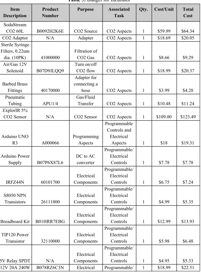
Budget
Table 5: Budget for Incubator Item
Description
Product Number
Purpose Associated Task
Qty. Cost/Unit Total Cost
SodaStream
CO2 60L B0092H2K6E CO2 Source CO2 Aspects 1 $59.99 $64.34
CO2 Adaptor N/A Adapter CO2 Aspects 1 $18.69 $20.05
Sterile Syringe Filters, 0.22um
dia. (10PK) 41000000
Filtration of
CO2 Gas CO2 Aspects 1 $8.66 $9.29 Air/Gas 12V
Solenoid B07D9JLQQ9
Turn on/off
CO2 flow CO2 Aspects 1 $18.99 $20.37
Barbed Brass
Fittings 40170000
Adapter for connecting a
hose CO2 Aspects 1 $3.99 $4.28
Pneumatic
Tubing APU1/4
Gas/Fluid
Transfer CO2 Aspects 1 $10.48 $11.24 ExplorIR 5%
CO2 Sensor N/A CO2 Sensor CO2 Aspects 1 $109.00 $123.49
Arduino UNO
R3 A000066
Programming Aspects
Programmable Controls and
Electrical
Aspects 1 $18 $19.31
Arduino Power
Supply B07P6X87L6
DC to AC converter
Programmable/ Electrical
Controls 1 $7.78 $7.78
IRFZ44N 60101700
Electrical Components
Programmable/ Electrical
Controls 1 $6.75 $7.24
S8050 NPN
Transistors 26111800
Electrical Components
Programmable/ Electrical
Controls 1 $4.99 $5.35
Breadboard Kit B01HRR7EBG
Electrical Components
Programmable/ Electrical
Controls 1 $12.99 $13.93
TIP120 Power
Transistor 32110000
Electrical Components
Programmable/ Electrical
Controls 1 $5.98 $6.48
5V Relay SPDT N/A
Electrical Components
Programmable/ Electrical
Power Supply Components Electrical Controls
Hinges x 2 240974 Hinged-Door Structural 2 $2.18 $2.34 2020 T-slot Aluminum Extrusion EXT-2020-REG-COMBO Physical build
for enclosure Structural 1 $79.95 $79.95 HDPE Plastic N/A Structural Structural 1 $53.97 $135.62
K-Type Thermocouple
+ MAX6675
Sensor N/A
Probe Temp Sensor
Temperature
Measuring 1 $5.90 $6.36 Air Heater
100W 12V B07JKNKK7J
Heating Element
Temperature
Measuring 2 $16.39 $35.38 12V DC Fan
(PWM, 4 Pins) B07CG2PGY6
Cooling inside Incubator
Temperature
Monitoring 1 $13.90 $14.91
i2c LCD 16x2 B019K5X53O LCD Screen
Temperature
Monitoring 1 $8.99 $9.64 Bubble wrap
Reflective Thermal
Insulation B000BPF22U
Temperature Control
Temperature
Monitoring 1 $9.98 $10.70 Digital
Thermometer and Humidity
Monitor B06XTPTG1J
Testing Temp.
Accuracy Testing Material 1 $11.86 $12.72
Foil Tape 119877
Temperature Control
Sealing the
Incubator 1 $4.42 $4.75 LocTite
Polyurethane
Sealant 1002938768
Temperature Control
Sealing the
Incubator 1 $11.99 $12.89 Total: $698.84
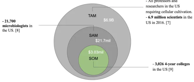
Total Available Market (TAM)
Total Available Market was done through a bottom-up analysis after investigating the market demand for our product. To build one incubator will cost us $698.84. Assuming we want to make a 30% profit on each unit we build, we aim to sell the DIY Incubator for $1000. We found that there are 6.9 million scientists in the United States, in the year of 2016 [7]. This is an
When we consider the Serviceable Available Market (SAM), we limit our market to those scientists that deal with bacterial cell culture directly. Finding that there are 21,700
microbiologists [8], our estimated annual revenue is $21.7 million at this level. Lastly, when we consider the Serviceable Obtainable Market (SOM) we search for a reasonable fraction of the SAM market that we can capture. This market would be educational school systems teaching STEM programs at 4-year universities. Finding that there are 3,026 4-year colleges in the US [9], we can project that our sales in SOM would be roughly $3.03 million. SOM is our short term potential but is an important target because if we cannot succeed in a first level market then we cannot begin to consider the larger markets in SAM or TAM.
Figure 2: TAM Breakdown
Competitive Advantage
Table 6. Competitive Advantage Matrix VWR Incubator,
Model 3500I [1]
Heracell VIOS 250i CO2 Incubator [6]
DIY Incubator
Unit Price $7,071.54 $15,000 $ 700
Dimensions 14W x 16H x 25.5L in.
30.5W x 38.1H x 36.8L in.
18W x 18H x 24L in.
FDA Cleared Yes Yes No
Voltage Output 120V AC 120V AC 110V AC
CO2 Sensor No Yes Yes
Orbital Shaker Yes No No
Humidity Water Bath
No Yes Yes
Intellectual Property Assessment
As with any product development, infringement on existing technologies must be examined. We conducted research on the United States Patent and Trademark Office website (uspto.gov) to better understand what technologies for incubators already exist and/or are protected by patent law. Of course, an incubator is not a novel technology. Because of this, we need to take precautions not to infringe on any current incubator patents. However, with this literature
available to us we will be able to pull from multiple sources to build the most effective incubator. Refer to Appendix AII for a list of patent numbers and their implications for our DIY incubator.
Conjoint Analysis
In the beginning stages of product development the team employed conjoint analysis techniques to determine which factors matter. It should be noted that conjoint surveys were taken by fellow undergraduate BMED students in the Senior Design course. For a more insightful analysis, the survey should be taken directly by the customer who has a deeper sense of the project and the specifications.
different combinations. Those who take the survey rank the cards from 1 to 8, one being the most desirable combination of factors and 8 being the least desirable combination of factors. Table 8 displays the combination of factors in each card.
Table 7: Conjoint Analysis Factors and Levels
Factors Level 1 Level 2
Cost $200 $500
Size 2’x2’x1’ 2’x1.5’x1.5’
Insulating material Fiberglass Polystyrene
Color Gray Black
Base 3D printed Machine shop assembly
Power Supply 110 V 220 V
Shaking Mechanism Orbital shaker Rocking shaker
Table 8: Conjoint Cards Per Taguchi Array
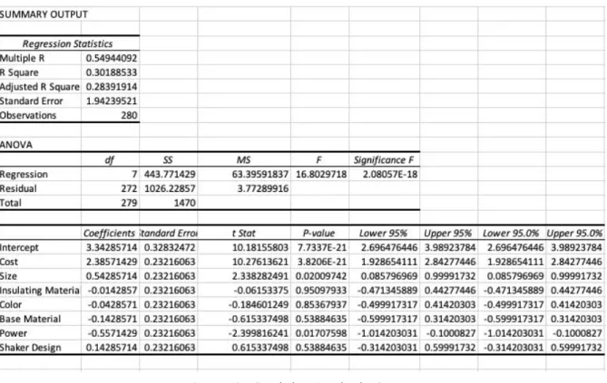
Figure 3: Conjoint Analysis Output
In this case, we disagree with the power supply mattering. We met with the customer after running this conjoint analysis and they confirmed that the outlet in the laboratory is 110V. With that customer need in mind, that conjoint analysis results will be overruled. In this case a bigger number is not necessarily better (220V is not better than 110V), demonstrating that the survey should ultimately be taken by the customer for the most helpful analysis. We accept that size and cost factors do matter. These factors help us understand what to focus on in product development as well as how to continue with future conceptual designs.
Morphology
Table 9: Morphology for DIY Incubator
Function Concept 1 Concept 2 Concept 3 Concept 4
Control temperature (heating element)
Cartridge heater Cartridge heater Space heater Immersion heater
Circulate air 12V DC Fan (1) 12V DC Fans (2)
12V DC Fan (1) 12V DC Fans (2) Monitor temperature/prov ide feedback Arduino with thermocouple for measuring temp ELEGOO with PID integrated system Arduino with PID integrated system ELEGOO with thermocouple for measuring temp Insulate
incubating space Polystyrene Water jacket Fiberglass Polystyrene pH control* No CO2 control No CO2 control Partial pressure
CO2 control
Acids/bases maintenance
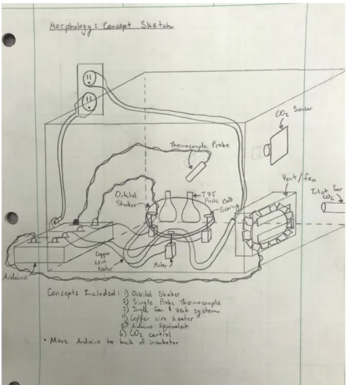
This Morphology assessment helped team members group together functions into full concepts. Each group member prepared a preliminary sketch of a different concept. The three sketches are presented below with a caption describing their combined elements.
Figure 4: Concept 1- A 2D sketch of concept #1 from the Morphology assignment. It
incorporates Heat Sinks as the heating element, one 12V DC Fan for the air circulation function, polystyrene as the insulation choice, and Arduino with thermocouple for measuring and
Figure 6: Concept 3- A 3-D sketch of concept #3 from the Morphology assignment . This
Concept Evaluation
The Morphology analysis yielded three concept sketches. To compare these ideas and identify a front-runner concept we constructed a Pugh Matrix. The Pugh technique allows for the
comparison of different concepts using one as a datum and ranking the others based on that datum. Each group member performed three Pugh matrix analyses, with each concept as the datum. The legend for Pugh matrix scoring is below in Table 10.
Table 10: Legend for Pugh Matrix Scoring
Relationship Value
Better than baseline 1
About the same 0
Worse than baseline -1
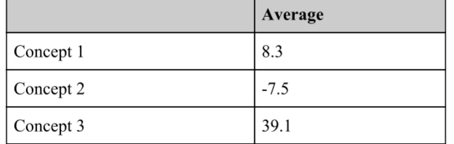
In total, nine Pugh matrices were generated for analysis. Table 11 below displays one of the nine matrices for reference. Total weighted scores for each concept were averaged and the concept with the highest average was identified as the front-runner concept, so long as all group members agreed with this conclusion. Average values are presented in Table 12 below.
Table 11: Example of our Pugh matrix
Issue: Identify front runner concept for DIY Incubator
Concept 1 Concept 2 Concept 3
Heating Element 30
Datum
-1 0
Air Circulation 10 0 1
Insulating Material 25 -1 -1
Temperature Monitoring 35 -1 0
Total -3 0
Table 12: Overall Average Scores for Each Concept Using Pugh Analysis Average
Concept 1 8.3
Concept 2 -7.5
Concept 3 39.1
Team members agreed with Pugh matrix average results, identifying Concept 3 as the
front-runner. Thus, the following elements were focused on for future development and further conceptual modeling: fiberglass insulation, an Arduino or equivalent integrated with a PID system, a 12V fan for air circulation, and a heater created by running an electrical current through a nichrome wire. In addition to the Morphology assessment and Pugh Matrix analysis, we also completed the Technology Readiness Assessment (TRA), which was an optional assignment for the scope of the BMED 455 class. The TRA was useful in helping us further evaluate our front runner concept, and balance technology maturity. We are pleased to know that our technology is mostly ready, and will lead to high quality functionality that our customers will value. The Technology Readiness Assessment for our project can be found in Appendix AV.
Conceptual Model
Figure 7: DIY Incubator conceptual assembly showing how mechanical components will fit together. The assembly is composed of six components:
Temperature sensor, fan, door, heating element, stand to hold T75 flasks, and base.
● The model development and analysis provided us a better understanding of the spatial limitations of the small footprint requirement. Creating a 3-Dimensional model of the incubator with all major components revealed that the footprint could be decreased while still meeting all customer requirements. The development of our model also helped us finalize which materials will be used for the structural base which allowed us to update and finalize our budget.
● The CAD designs will help us tremendously when building our prototype design. We now have a great plan for what we want the model to look like. These drawings also provide us with confidence that our design is possible, based on the geometry and constraints. Furthermore, the CAD designs will also allow us to communicate with other engineers, machine shop techs, and manufacturing vendors if we need help with the physical building of our prototype.
Detailed Design
At this stage of product development we are confident in our geometry, materials, and
manufacturing procedures for the DIY Incubator. After several iterations and integrating sponsor input, our final concept is as follows in Figure 9.
The final design of the structural exterior of the incubator consists of 2020 aluminum with ¼ inch HDPE walls inserted into the slots of the aluminum. The components housed within or inserted into the incubator are the following: thermocouple, flask holder, water bath, filter, heating element, and plug. The heating element is a heater and fan integrated into one system which is represented by the 4” x 4” x 8” block located near the door of the incubator. There are two circular inlets cut into the walls of the incubator: one for the influx of CO2 located near the top of one of the side walls and one for the thermocouple located halfway up the back wall of the incubator. The inlet for the CO2 is located near the top of the incubator to account for the fact that CO2 is more dense than air. The detailed drawings of all major components of the structural portion of the incubator are shown in the figures below. All dimensions are given in millimeters.
Figure 11: Fusion 360 drawing of T-75 Flask Holder
Figure 13: Fusion 360 drawing of Plug located on the top of the Incubator
Final Design Dimensioning
An original requirement from our sponsor for the DIY Incubator was a small physical footprint. The overall footprint of the incubator is 22” x 16” x 15.5”. We have dimensioned the enclosure to fulfill this requirement and have confirmed through 3D modeling that all internal components will comfortably fit inside.
Material Selection
Table 13: Material Selection for Frame
Material Wood 2020 Aluminum Slots
Price + =
Size Versatility + +
Steps to Manufacture and Assemble
- +
Interaction by Cleaning Solutions
- +
Table 14: Material Selection for Walls
Material Acrylic High-Density Polyethylene
(HDPE)
Price - +
Size Versatility + +
Steps to Manufacture and Assemble
= =
Interaction with Cleaning Solutions
+ +
2020 aluminum slots were chosen for the frame of the incubator because they are easier to manufacture and assemble compared to wood. Although they are more expensive, being able to buy them already manufactured results in fewer steps required to prepare them for assembly. HDPE was chosen over acrylic due to its cheaper price per square inch.
Cost Estimation
Prototype Manufacturing Plans
This section provides an in depth explanation of manufacturing procedures for the DIY Incubator including enclosure assembly and electrical circuitry layout. Refer to the Bill of Materials for specific parts, numbers, and vendors for the prototype.
Manufacturing Process Instructions (MPI) for Structural Components Step 1
Required Materials: 2020 Aluminum Extrusions (Part # EXT-2020-REG-COMBO) Required Tools: Aluminum Miter Saw, Writing Utensil
Using an aluminum miter saw, cut the 2020 Aluminum Extrusions into four 20.5” pieces, four 15.625” pieces, and four 14.0” pieces. Using the writing utensil, label the 20.5” pieces “Long”, the 15.625” pieces “Horizontal”, and the 14.0” pieces “Vertical” in order to keep track of the different size cuts.
Step 2
Required Materials: Cut 2020 Extrusions, Aluminum Connectors (Part # EXT-2020-REG-COMBO)
Required Tools: Allen Wrench
Figure 14: Completed Three-way Junction
Step 3
Required Materials: 48” x 48” x 3/16” HDPE Sheet (Part # 8619K457) Required Tools: Table Saw, Writing Utensil
Using a standard table saw, cut out two 20.75” x 14.5” pieces from the HDPE sheet. Label the sheets “Top” and “Bottom”. Next, cut out two 20.25” x 14.0” pieces and label them “Front” and “Back”. Finally, cut two 14.5” x 14.0” pieces. Label the pieces “Side with no Cuts” and “Side with air Filter”.
Step 4
Required Materials: Aluminum Insulation (Part # B000BPF22U) Required Tools: Scissors
Using scissors, cut out two rectangular pieces of insulation 20.25” long x 14.0” wide and label them “Top” and “Bottom”. Then, cut out two 19.75” x 13.5” rectangular pieces of aluminum insulation. Label these two pieces “Front” and “Back”. Next, cut out two 14.0” x 13.5” pieces. Label these pieces “Side with no Cuts” and “Side with Air Inlet”. Finally, cut out a piece of 7.0” x 12.75” and label it “Door”.
Step 5
Required Materials: Cute HDPE Pieces Required Tools: Laser Cutter
Figure 15: Fusion 360 drawing of “Top” HDPE Piece
Next, using the laser cutter, cut three 2.5” x 0.05” rectangular slots into the HDPE piece labeled “Side with Air Inlet”. The location and dimensions for the cuts are shown below in Figure 16.
Figure 16: Fusion 360 Drawing of “Side with Air Inlet”
Figure 17: Fusion 360 Drawing of “Front” HDPE Piece
Step 6:
Required Material: HDPE Cut Labeled “Back” Required Tools: ¼” Drill Bit, Drill Press
Using a drill press and a ¼” drill bit, cut a ¼” hole into the center of the HDPE piece labeled “Back”. This hole will be used to insert the thermocouple.
Step 7:
Required Materials: Cut HDPE Pieces, Cut Aluminum Insulation Pieces Spray Adhesive (Part # 1002832578)
Required Tools: None
First, match the corresponding cut pieces of aluminum insulation with their corresponding pieces of HDPE pieces based on how each was labeled. Cover the entirety of one side of the aluminum insulation with spray adhesive. Adhere the aluminum insulation its corresponding piece of HDPE leaving 0.25” of visible HDPE on all sides. Once the aluminum is adhered, cover the aluminum with a dense mass to ensure it adheres strongly to the HDPE. Do this for all seven corresponding matches of aluminum insulation and HDPE.
Step 8:
Required Material: HDPE Cuts with Aluminum Insulation Adhered Required Tools: ExactoKnife
Step 9:
Required Materials: HDPE Walls with Aluminum Insulation, Spray Adhesive Required Tools: Clamps
Beginning with the bottom wall, spray adhesive onto the exposed bottom aluminum connections. Place the bottom wall onto the supports with the aluminum insulation facing upwards. Secure clamps over the connections and HDPE piece to ensure the two adhere together tightly. Repeat this step with the “Front” wall, “Back” wall, “Side with no Cuts”, and “Side with Air Filter” with the aluminum insulation facing inward towards the center of the incubator. Ensure the clamps are tight and not bending the HDPE. An example image of clamping down the HDPE is shown below in Figure 18.
Figure 18: Securing the HDPE Walls to Aluminum Connectors
Step 10:
Required Material: Remaining Cut 2020 Aluminum Extrusions, Aluminum Connectors Required Tools: Allen Wrench
Using the remaining cut aluminum extrusions and aluminum connectors, create three-way junctions composed of one of each length of the aluminum extrusions. The aluminum connectors slide into the slots of the 2020 aluminum extrusions and tighten down using an allen wrench.
Step 11:
Required Tools: None
Apply spray adhesive to the top connectors of the incubator. Slide the “Top” wall of the
incubator onto the four vertical walls and under the top connectors. If the wall cannot slide easily into the open space for it, unscrew two of the top connectors, insert the top wall, and then replace the removed brackets.
Step 12:
Required Materials: Foil Tape (Model # 119877) Required Tools: Scissors
Apply foil tape to the inside of the incubator enclosure at the edges where two pieces of HDPE interphase. Ensure the foil tape tightly adheres to the aluminum insulation to seal the enclosure.
Step 13:
Required Materials: LocTite Polyurethane Sealant (Item #1050673) Required Tools: Caulking Gun
Using a caulking gun, apply LocTite polyurethane sealant along the external edges where the HDPE walls meet the aluminum extrusions to completely seal the box.
Manufacturing Process Instructions (MPI) for Incubation Stand Step 1:
Required Materials: 2020 Aluminum Extrusions Required Tools: Aluminum Chopsaw
Using the aluminum chop saw, cut four 5” pieces of 2020 aluminum extrusion, two 9” pieces, and two 11.25” pieces.
Step 2:
Required Materials: HDPE Sheet
Required Tools: Jigsaw or Plastic End Mill
Figure 19: HDPE for Incubation Stand
Step 3:
Required Material: Four 2020 Aluminum Connectors, 9” and 11.25” Aluminum Cuts from Step 1, HDPE piece from Step 2
Required Tools: Screwdriver
Figure 20: Image of the Completed Incubation Stand Top
Step 4:
Required Material: Eight 2020 Aluminum Connectors and the Four 5” Aluminum Pieces Required Tools: Screwdriver
Attach the 5” pieces of 2020 aluminum to the top of the incubation stand at all four corners as seen in Figure 21.
Manufacturing Process Instructions (MPI) for Electrical Components
After meeting with our sponsor and discussing the electrical/programmable aspects of the incubator, we were able to create a simple block diagram (Figure 22). This diagram serves as a guide to visualize the flow of where connections and parts need to go. Note that it is not intended to serve as a detailed schematic drawing, but it will be very useful for integrating all the
components as one system at the final stage. A detailed view of schematic drawings and associated Arduino codes will be discussed more thoroughly in the later section of this MPI.
Figure 22: Simple Block Diagram of Electrical Components
Thermocouple Integration:
seeing if the thermocouple responds. In our case, we applied pressure using our fingers to the thermocouple probe which created a small amount of change in heat to the temperature reading, verifying that the thermocouple and sensor system worked as intended. More testing of the thermocouple can be found in our Test Plans section.
Figure 23: Schematic for Thermocouple integration with Arduino
#include"max6675.h"
int soPin = 4;// SO=Serial Out
int csPin = 5;// CS = chip select CS pin int sckPin = 6;// SCK = Serial Clock pin
MAX6675 thermocouple(sckPin, csPin, soPin);
voidsetup() {
Serial.begin(9600);
// give the MAX a little time to settle
delay(500);
voidloop() {
// basic readout test
Serial.print("Deg C = ");
Serial.print(ktc.readCelsius());
Serial.print("\t Deg F = ");
Serial.println(ktc.readFahrenheit());
delay(500); }
Figure 24: Arduino Code for Thermocouple Integration
LCD Screen + Thermocouple Integration:
An additional add-on to the incubator was to display the real-time temperature from the thermocouple on a LCD screen (part no. B019K5X53O). The picture below shows how this system is set up, essentially the process is identical to the previous section Thermocouple
Integration, which utilizes a Max6675 sensor, but this time the LCD screen is also added into the Arduino, followed by the proper Arduino code which includes a new library “LiquidCrystal.h.” Pins GND, Vin, A4, and A5 were connected from the ports of the LCD display to the Arduino.
#include"max6675.h"
#include<Wire.h>
#include<LiquidCrystal_I2C.h>
// Set the LCD address to 0x3F for a 16 chars and 2 line display
LiquidCrystal_I2C lcd(0x27, 16, 2); // end of settings for LCD1602 with I2C
int soPin = 4;// SO=Serial Out
int csPin = 5;// CS = chip select CS pin int sckPin = 6;// SCK = Serial Clock pin
MAX6675 thermocouple(sckPin, csPin, soPin);
voidsetup() {
lcd.begin();// initialize the LCD1602
lcd.backlight();// turn the backlight ON for the LCD lcd.print("Hello");
lcd.setCursor(0,1);
// lcd.print("Thermocouple");
Serial.begin(9600);// initialize serial monitor with 9600 baud
delay(3000);// give time to user to read the display at the beginning
}
voidloop() {
// basic readout test, just print the current temp
Serial.print("C = ");
Serial.println(thermocouple.readCelsius()); Serial.print("F = ");
// Serial.println(thermocouple.readFahrenheit());
lcd.clear();// clear previous values from screen
lcd.setCursor(0,0);// set cursor at character 0, line 0 lcd.print("Temp");
lcd.setCursor(0,1);// set cursor at character 0, line 1 lcd.print(thermocouple.readCelsius());
lcd.setCursor(6,1);// set cursor at character 9, line 1 lcd.print("C");
delay(1000);}
Figure 26: Arduino Code for LCD Screen With Thermocouple
CO2 Integration:
Figure 27: CO2 Sensor Integration with Arduino [10]
/*
Arduino________COZIR Sensor GND --- 1 (gnd) 3.3v--- 3 (Vcc) 13 --- 5 (Rx) 12 --- 7 (Tx) */
#include"cozir.h"
#include"SoftwareSerial.h"
SoftwareSerial nss(12, 13); // Tx, Rx from the sensor to Pins 2, 3 on Arduino COZIR czr(nss);
float c, reading = 0;
float multiplier = 10; // 0.001 = 10/10000 (Hardware multiplier/ppm conversion) // For more details see sensor specificaiton sheet
voidsetup()
{
czr.SetOperatingMode(CZR_POLLING);
delay(100);
}
voidloop() {
c = czr.CO2(); // read the sensor, values output as ppm reading = c*multiplier; // convert ppm reading to percentage Serial.print("CO2 Content: ");
Serial.print(reading); Serial.println(" PPM"); // Serial.println();
delay(50);
}
Figure 28: Arduino Code for CO2 sensor
Figure 28, above shows the CO2 sensor integration with the Arduino UNO R3. The electrical wiring was found from a resource online [10]. We connected our CO2 sensor the same way and developed our own Arduino code for functionality of the sensor to output PPM values in real time. More specific testing can be found in the Test Plans.
12V DC Fan Integration:
The figure above shows the integration of our 12V DC Fan for the DIY Incubator. The electrical wiring is quite simple and straightforward, we just hooked up the negative and positive sides of the fan using two Male-to-Female wires which then connect to the respective negative and positive sides of the AC to DC power transformer (part no. B078RZ6C3N). There is no code necessary to run the fan at full speed and continuously. An AC to DC power supply transformer is used in our project to ensure that the proper voltage and current is supplied to the higher electrical components, such as our 100W Heating Element, 12V DC fan, and Solid State Relay. The way the transformer turns on and converts AC to DC power is through using 3 prong wires of an AC cable and connecting them to their respective connection ports (live, neutral and earth). The color of these wires follow this format: live = black; neutral = white; earth = green. The 3 prong wires were made possible by using a wire stripper and crimping tool to produce the desired electrical connections pictured in Figure 30.
Heating Element Integration:
Figure 31: 100W DC Air Heater Integration
Figure 31 shows the heating element integration of our DIY Incubator. We used a DC 12V, 8.3A Air Heater which connects to the power transformer and Solid State Relay (SSR) directly. It is important to point out that the relay is the interface that connects to the Arduino, and acts as an electrical switch for when heat is supplied or shut off. The following Arduino code is how we got the SSR to be recognized and work with the Arduino.
// SSR Relay
int relayPin = 8;// set pin 8 for relay output
// setup code for Solid State Relay
voidsetup() {
// initialize serial communication at 9600 bits per second:
Serial.begin(9600);
pinMode(relayPin,OUTPUT);
}
// Turn the relay switch ON
digitalWrite(relayPin,HIGH);// set relay pin to HIGH
Serial.println("Relay ON ");
delay(2000);
// Turn the relay switch OFF
digitalWrite(relayPin,LOW);// set relay pin to LOW
Serial.println("Relay OFF ");
delay(2000); }
Figure 32: Arduino Code for the Solid State Relay
Installation of the Electric In-line Switch (Part #B00826P0AO) Step 1:
Required Materials: Cable for Power Supply Required Tools: Wire Strippers
Select a point about one and a half feet from input plugs of the power cable. Using the wire strippers, strip the outer rubber coating off the cable until the three interior wires are exposed. Repeat this approximately four inches farther down the cable toward the end of the cord which inserts into the wall. Ensure you do not strip the interior wires.
Step 2:
Required Materials: Cable for Power Supply Required Tools: X-Acto Knife
Using the X-Acto knife, cut through the outer rubber along the length of cable in between the two areas of exposed wire. Once the outer rubber has been cut, remove the rubber coating from the cable. Be careful not to cut any of the three interior wires.
Step 3:
Required Materials: Cable for Power Supply Required Tools: Wire Strippers
Find the hot wire and use the wire strippers to cut through the wire one inch from each end where the outer cover was stripped. Then strip about half an inch of each cut end of the hot wire using the wire strippers.
Step 4:
Required Materials: Cable for Power Supply Required Tools: Wire Crimper, Two Spade Plugs
Step 5:
Required Materials: Cable for Power Supply, In-line Switch Required Tools: Screwdriver
Unscrew the two screws on the exterior of the in-line switch shown in Figure 33 below.
Figure 33: Exterior Screws on the In-Line Switch
Step 6:
Required Materials: Cable for Power Supply Required Tools: Screwdriver
Figure 34: Opened In-Line Switch
Step 7:
Required Materials: Electrical Tape Required Tools: None
Apply electrical tape around the areas of the wire directly preceding both ends of the inline switch to ensure there are no exposed wires.
Final System Setup:
The final system setup involves putting all the components that we got to work individually, all in one system with one finalized working Arduino code. A picture of how this setup looks is shown in Figure 35 below. The final code can be found in Appendix AVII.The final code essentially combines the works of all previously mentioned components in the MPI, and adds a condition for temperature setpoint, where the user can enter the desired temperature, in degrees celsius and the Arduino will either instruct the SSR to turn on or off based on the temperature recording of the thermocouple.
Figure 35: Final System Setup for Electrical Components of DIY Incubator
Step 1: Connect Arduino UNO to Solid State Relay (SSR); pin 8 = positive input of SSR, GND = negative input of SSR
Step 2: Ensure the proper connections are set for the Max6675 sensor, which connects to the K-Type Thermocouple (refer to Figure 23 for wiring)
Step 3: Connect Arduino to LCD (refer to Figure 25 for wiring)
Step 4: Connect power to the AC to DC transformer, by connecting the 3 wires from the AC cable to Live, Neutral, and Earth (color schemes found in Figure 29).
Step 6: Connect the air heater by placing the 2 negative (black) wires to the COM of the power supply transformer and placing the 2 positive (red) wires to the positiv e end of the SSR output terminal.
Step 7: Plug power into the Arduino and transformer by directly plugging them into a 110V wall outlet.
Below in Figure 36 is the system setup for the CO2 components of the incubator. The CO2 inlet system consists of a solenoid, solid-state relay (SSR), CO2 source, regulator, Arduino, power supply, and pneumatic tubing. The Arduino and solenoid are connected to the SSR in order for the Arduino to control when the solenoid should open in order to let CO2 flow into the incubator. The regulator controls the pressure of the CO2 flowing through the pneumatic tubing and should be set between 10 and 12 PSI when the incubator is operating.
Bill of Materials
Table 15 details a comprehensive list of parts required to build the DIY Incubator.
Table 15: DIY Incubator Bill of Materials
Part Description Associated Task Part Number Vendor Quantity
SodaStream CO2 60L CO2 Aspects B0092H2K6E Amazon 1
CO2 Tank Adaptor CO2 Aspects N/A Amazon 1
Sterile Syringe Filters, 0.22um dia.
(10PK) CO2 Aspects 41000000 Amazon 1
Air/Gas 12V Solenoid CO2 Aspects B07D9JLQQ9 Amazon 1
Barbed Brass Fittings CO2 Aspects 40170000 Amazon 1
Pneumatic Tubing CO2 Aspects APU1/4 Amazon 1
ExplorIR 5% CO2 Sensor CO2 Aspects N/A CO2Meter 1
Arduino UNO R3 Programmable/Electrical Controls A000066 Amazon 1
Arduino Power Supply Programmable/Electrical Controls B07P6X87L6 Amazon 1
IRFZ44N Power Transistor MOSFET Programmable/Electrical Controls 60101700 Amazon 1
S8050 NPN Transistors Programmable/Electrical Controls 26111800 Amazon 1
Breadboard Kit Programmable/Electrical Controls B01HRR7EBG Amazon 1
TIP120 Power Transistor Programmable/Electrical Controls 32110000 Amazon 1
5V Relay SPDT Programmable/Electrical Controls N/A Ebay 1
12V 20A 240W Power Supply
Transformer Switch Programmable/Electrical Controls B078RZ6C3N Amazon 1
Hinges Structural 31162403 Grainger 2
2020 T-slot Aluminum Extrusion Combo Structural
EXT-2020-REG-CO
MBO Zyltech 1
.125” x 24” x 48” HPDE Plastic Structural N/A ePlastics 3
K-Type Thermocouple + MAX6675 Temperature Measuring B00PVTH4MW Ebay 1
Air Heater 100W 12V Temperature Measuring B07JKNKK7J Amazon 2
12V DC Fan (PWM, 4 Pins) Temperature Monitoring B07CG2PGY6 Amazon 1
i2c LCD 16x2 Temperature Monitoring B019K5X53O Amazon 1
Bubble wrap Reflective Thermal
Insulation Temperature Monitoring B000BPF22U Amazon 1
Foil Tape Sealing the Incubator 119877 Home Depot 1
LocTite Polyurethane Sealant Sealing the Incubator 1002938768 Home Depot 1
Required Facilities, Equipment, and Training
In order to assemble the DIY Incubator the team will need access to several facilities and resources. Dimensioning the aluminum extrusions and cutting the HDPE enclosure walls will require access to the Cal Poly Machine Shops. All team members have secured their yellow tag and will have full access to all necessary equipment in the shops, such as the aluminum chop saw, tablesaw, mill, screwdrivers, drill press, and metal sander. The team will also have access to the Electrical Engineering Lab in Building 20, Room 111 at the Cal Poly campus. This is a great resource for electrical circuitry testing, as we will need access to oscilloscopes, voltmeters, resistors, cables, wires, and other electrical components.
Safety is a high priority as we build the DIY Incubator. The team is aware of risks of physical assembly as well as potential electrical injuries from circuitry work. We have developed strategic plans for safety in all aspects of our project. Refer to Appendix AVI for the Hazards and Risks Assessment for the DIY Incubator. A rule for the structural building of the Incubator is to have at least 2 group members present for help at all times, that way no one is left working alone and someone is always present in the case of an emergency. For the electrical components, we will test individual parts — fan, heating element, thermocouple, and CO2 control — separately and confirm these parts are working properly before combining all of the necessary components as one unit, helping to prevent potential hazards along the way.
Test Plans
PurposeTesting the DIY Incubator is a critical step in our product development. We want to validate all of our customer requirements to ensure we are delivering on every specification. Certain metrics can be easily assessed such as production cost, size, incubation space, and voltage power source compatibility. Production cost will be assessed through budgeting; assuming we do not exceed our $700 dollar budget, then this spec has been met. Incubation space and size are both
dimensional measurements and we will measure upfront to ensure the geometry of the DIY Incubator is satisfactory. Voltage power source compatibility is achieved through the integration of our 240W power supply transformer.
Specifications that require additional testing are temperature control, correcting period, and CO2 partial pressure control. Before the ultimate design can be assessed, we need to evaluate
Figure 37: Testing Network Diagram with critical path highlighted in red Table 16: Testing Network Diagram Legend
Task Description Dates Location Resources
Needed
1 Fan Testing 1/23 - 1/24 Garrett’s House Paper, Multimeter
2 Thermocouple Testing 1/24 - 1/28 Aryan’s House Thermometer
3 Heating Element Testing 1/29 - 1/31 Aryan’s House Thermometer
4 CO2 Individual Testing 1/23 - 2/5 Garrett’s House CO2 Source
5 Temperature Control Testing 2/3 - 2/12 Hawkin’s Lab Infrared
Thermometer Gun
6 Correcting Period Testing 2/13 - 2/27 Hawkin’s Lab Timer
7 CO2 Partial Pressure Testing 2/6 - 2/27 Garrett’s House CO2 Source, Timer
8 Senior Project Design Report 2/27 - 3/10 Cal Poly Campus N/A
Pre-System Setup
Initial testing will be to ensure all our parts work properly with the expected specs and output. The following circuits will be tested to ensure individual viability: fan, heating element, thermocouple, and CO2 injection.
Figure 38: Fan half speed test setup
To test the fan at full speed, refer to the setup in Figure 39, where the fan is connected to the power supply through two wires. Under both testing conditions, the fan fulfills the testing criteria if it powers on and runs at its predicted wattage value. We will use a multimeter to verify the power consumption to test the effective speeds. Table 17 summarizes the testing criteria for the fan element.
Table 17: Fan Testing Criteria
Test Description Pass Criteria Fail Criteria
Fan half speed test Fan is able to run for 5 minutes at 0.5W
Fan does not run
Fan full speed test Fan is able to run for 5 minutes at 1.0W
Fan does not run
2. Test 2- Thermocouple Temperature Test: We will ensure the thermocouple reports accurate temperature readings by testing it in various standard temperature conditions. The thermocouple will be subjected to the following environments: room temperature, boiling water, and ice water. We expect the thermocouple to read 22°C, 100°C, and 0°C respectively. To test the following conditions, refer to Figure 40 where the thermocouple is connected to the Arduino and LCD screen. Note the LCD screen displays the
temperature detected by the thermocouple. Table 18 below summarizes the testing criteria for the thermocouple.
Table 18: Thermocouple Testing Criteria Test Description Pass Criteria Fail Criteria
Room temperature test Thermocouple reads 22 ± 2°C Thermocouple does not read 22 ± 2°C Boiling water test Thermocouple reads 100 ± 1°C Thermocouple does not read 100 ± 1°C Ice water test Thermocouple reads 0 ± 1°C Thermocouple does not read 0 ± 1°C
3. Test 3- Heating Element Maximum Temperature Test: We will ensure the heating element works by running the air heater continuously until the thermocouple reads an interior temperature of 45° (the maximum of the temperature range defined by our sponsor). The time required to heat the incubator to 45° will be recorded. The test will be repeated two times to ensure the data is repeatable. This results in a sample size of three. To test the heating element, refer to the setup in Figure 41, where the power supply is connected to the heating element, solid state relay, and Arudino. Table 19 below summarizes the testing criteria for the heating element.
Table 19: Heating Element Testing Criteria
Test Description Pass Criteria Fail Criteria
Heating element maximum temperature test
Heating element warms incubator to 45°C in 60 minutes or less
Heating element does not warm incubator to 45°C after 60 minutes
4. Test 4- CO2 Sensor Validation Test: We will ensure the CO2 sensor is working properly by testing the part against known PPM conditions . We will also test the CO2 sensor to confirm the part registers changes in CO2. To test the CO2 sensor, refer to Figure 42, where the CO2 sensor is connected to the Arduino. Figure 28includes the full Arduino code for the CO2 sensor. Table 20 below summarizes the testing conditions for the CO2 elements.
Figure 42: CO2 Sensor Testing Setup
Table 20: CO2 Validation Testing Criteria
Test Description Pass Criteria Fail Criteria
CO2 sensor test Sensor detects increase in PPM when introducing CO2 to it and matches Fyrite reading (±0.5%)
Sensor fails to display PPM values or does not match the Fyrite values (±0.5%)
Table 21: CO2 Validation Contingency Testing Criteria
Test Description Pass Criteria Fail Criteria
CO2 sensor test (contingency plan)
Outdoor air partial pressure reads between 250-400 PPM
Outdoor air partial pressure reads below 250 PPM or above 400 PPM
System Setup
Once the DIY Incubator is fully assembled and individual components have been verified, holistic testing will ensure the entire system fulfills customer requirements. Metrics that need to be verified in this phase of testing are temperature control, correcting period, and CO2 partial pressure control.
5. Test 5- Thermocouple Validation Test: In addition to validating the thermocouple vs known temperatures, we will also validate the thermocouple against an infrared
thermometer gun once the system is fully set up. We will have the door of the incubator open and measure the temperature of the air inside. This procedure will take place at a setpoint temperature of 37°C. The Arduino monitor on the computer screen will report degrees Celcius from the K-type thermocouple and one member of the team will record the temperature reading from the infrared thermometer gun. Measurements will be taken every 3 seconds for a total of 4 minutes. This results in a sample size of 81. Temperature data from the K-type thermocouple will be compared to the temperature output of the thermometer gun.
Table 21: Thermocouple validation testing
Test Description Pass Criteria Fail Criteria
Temperature validation: K-type thermocouple vs infrared thermometer gun
K-type thermocouple reads within 1°C of the
thermometer gun for 4 mins
K-type thermocouple and thermometer gun vary in temperature by more than 1°C during the 4 mins
6. Test 6- Temperature Control Test: To verify temperature control of the DIY Incubator we will input a setpoint temperature using code saved onto the Arduino. Once a setpoint has been reached we will use the Arduino serial monitor to record temperature
measurements inside the incubator for 10 minutes. As long as the temperature setpoint does not change and is within the target range of 25-45°C, the incubator should maintain that temperature within ± 1°C. This test will consist of nine runs with three runs at each of the following initial setpoint temperatures: 25°C, 37°C, and 45°C. The resulting sample size is three. Table 22 details the testing criteria for temperature control of the incubator.
Table 22: Temperature Control Testing Criteria
Test Description Pass Criteria Fail Criteria
Temperature setpoint control test
Heating element maintains setpoint in the range 25-45°C within ± 1°C
Heating element fails to maintain setpoint in the range 25-45°C with ± 1°C
7. Test 7- Correcting Period Test: To verify a correcting period of 10 minutes, we will run a series of tests to determine if the incubator can return to a setpoint once it deviates from that input. Following each run of test 6 (Temperature Control Test), we will open the door of the incubator to allow room temperature air inside, thus lowering the internal temperature by 3 to 4°C. This will simulate conditions the incubator will be subjected to during everyday use (e.g. cleaning and cell maintenance). We will then begin recording temperature readings inside the enclosure for 10 minutes. To do so we will utilize the Arduino serial monitor tool. This test will consist of nine runs with three runs at each of the following initial setpoint temperatures: 25°C, 37°C, and 45°C. We expect the
incubator to return to the setpoint within that 10 minute period. The resulting sample size is three. Table 23 summarizes the test criteria for the correcting period test.
![Table 6. Competitive Advantage Matrix VWR Incubator, Model 3500I [1] Heracell VIOS 250i CO 2 Incubator [6] DIY Incubator Unit Price $7,071.54 $15,000 $ 700 Dimensions 14W x 16H x 25.5L in](https://thumb-us.123doks.com/thumbv2/123dok_us/8222555.2179967/14.918.164.778.135.577/competitive-advantage-matrix-incubator-heracell-incubator-incubator-dimensions.webp)