Abstract—Falling film column is a versatile piece of process equipment, which can be used as absorption, desorption, evaporation and distillation. In present work a utility two pass falling film column was used as gas-liquid desorber, operating in continuous mode of operation. Free HCl gas dissolved in 2-EHCF product was stripped/desorbed by using hot water utility. A diffusion based mathematical model was proposed to estimate effect of film thickness and column height on concentration of dissolved gas theoretically. Simulation with MATLAB shows a reasonably good agreement with experimental data. A systematic procedure is also presented for design of various critical process parameters. Work was further extended to study the absorption with chemical reaction for two different products.
Index Terms—Absorption, desorption, falling film, mass transfer.
I. INTRODUCTION
In present work, desorption process for liquid products for the removal of gaseous materials is carried out at high temperature and under negative draft in Continuous Falling Film Column.
When preheated liquid flows down gradually over the heated surface in the form of thin film, free gases are stripped off and then absorbed in an alkaline solution i.e. NaOH solution. The key advantage is that the process does not require any carrier gas i.e. Nitrogen or Air or agitation to remove free gases.
Process can be carried out in a Falling Film Column in which liquid flows down in the form of a thin film in the narrow vertical passage (2.00x10⁻³ m) of the column. Heating is provided by using hot water (333 to 363 °K) which is circulated in the utility line of the column. At the top of the column, suction line (15-50x10-3 m WC) is provided to vent the stripped gases from the column. At this temperature and negative draft, liquid falls down over the hot surface and gases get desorbed and are sent to the scrubbing system. During its passage, it gets heated for continuous degasification. Product is collected in receiver.
In this degasification process carried out in Falling Film Column, product quality (GC purity) of the material being degassed does not change. Product doesn’t get decomposed due to high temperature. As hot water is circulated under controlled temperature, product is not overheated or no hot spots are observed.
Manuscript received October 5, 2011; revised January 30, 2012. The authors are working as Deputy Manager - Process Engineering Research Group, at Alembic Pharmaceuticals Limited, Vadodara, Gujarat, India,( [email protected])
Srivastava V. K. et al. [1] developed a mathematical model for the thin film reactor, where in the mass transfer takes place with chemical reaction. They solved the coupled partial difference equation which describes the mass and heat transfer in the liquid by finite difference method using implicit scheme. They observed the difference between the concentration gradient and temperature gradient due to the sensitivity of the model parameters. The temperature increases with axial distance due to the exothermicity of the reaction. Although concentration of gas has a significant effect in radial direction but negligible change has been observed for the variation of temperature which is because of small thickness of the liquid film resulting in not much exothermic effects occurring in radial direction. The maxima of interfacial temperature and the mixed mean liquid temperature increases within a short distance from the inlet due to the high exothermicity of the reaction for instantaneous reaction.
Nielsen P. H. et al. [2] explained the existence of an extraordinary large number of steady state solutions by the coupling between absorption and reaction in a falling film column. A low temperature gives no reaction, a high temperature prevents absorption of the gas and hence leads to mass transfer control of the reaction, while an intermediate temperature may permit operation at a third (stable) steady state. They extended the analysis of the CSTR to the distributed system of a falling film reactor and they treated both the transient situation in the entrance part of the column and the steady state which is reached further down. The two-dimensional falling film reactor with temperature gradient across a gas film and through the liquid film presents considerable numerical difficulties which have not been circumvented in earlier simulations without sacrificing important features of the model by simplifications. They investigated a reasonably complete analysis of an exothermal reaction on a two-dimensional laminar film. Gas film resistance to heat transfer plays a major role in the behavior of the film reactor and it must undoubtedly be taken into account. It is shown that at most 5 steady states can exist, both in the case of an isothermal liquid film and when the temperature is allowed to vary across the liquid film.
Talens F. I. et al. [3] analyzed the general and specific limitations of available models for falling film chemical reactors. They proposed an improved model which has been found to perform well in industrially relevant conditions. For its specific application to sulphonation/sulphation reactions yielding anionic surfactants, their improved model provides enhanced predictions about reactor performance, including relative color intensity at different operational conditions. Correlations for frictional drag between gas and liquid should
Process Modeling, Simulation and Design of Multi Pass
Falling Film Desorber
be obtained for specific reactor like falling film reactor. A reasonably approach could be the one where interfacial effects are associated with a roughness factor. They observed that spatially averaged film thickness is an assumption which seems to work better at high gas-liquid shear stresses.
Xu Z. F. et al., Khoo B. C. et al. [4] developed a numerical simulation for a vertical and inclined type falling film arrangement under the influence of gravity. The hydrodynamic characteristics like film thickness, velocity distribution and wall shear stress variations affect the interfacial and wall-to-liquid heat and mass transport processes. They concluded that the numerical simulation provides a way to view the local and mean transfer parameters especially the relation of the mass transfer velocity and the gradient of vertical fluctuating velocity at the interface. The presented simulation suggested that the gradient of vertical fluctuating velocity at the interface can be the all-important near-surface hydrodynamic parameter governing the scalar transport across the interface due to limited range of thin film flow conditions.
Banerjee S. et al. [5] introduced a theory which allows liquid phase mass transfer co-efficient to be predicted from knowledge of the wavelengths, wave frequencies and liquid flow rates. This theory makes it unnecessary to know the velocity profile within the film. This theory is applicable for a range of flow which is largely laminar; i.e. a range in which the dominating mechanism of mass transfer is not transport by turbulence eddies but is unsteady molecular diffusion into a largely laminar fluid which is intermittently mixed by eddies which are associated with the fluid wave structure. It can be concluded that in very short columns, the mass transfer in the column length preceding the line of wave inception would have to be considered.
Fujita I. et al. [6] proposed the method to calculate heat and mass transfer coefficients of falling film absorption process over vertical tube or plate type surface employed in absorption refrigeration system. This method was demonstrated by numerical simulations and comparison analysis. They analyzed the different methods of calculating the coefficients and reveal the defects of conventional methods using log mean temperature/concentration differences. They presented good results by numerical simulation under the assumption of linear distribution of the coolant temperature, solution concentration and interfacial equilibrium temperature.
II. DESCRIPTION OF FALLING FILM COLUMN
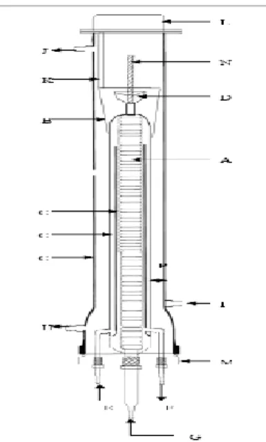
A Schematic Sketch shown in Fig.1 is a - “FALLING FILM COLUMN”. Industrially it is also known as Falling Film Calandria or Wetted Wall Column, used for unit operations. Conventional use of falling film phenomena is for various unit operations like absorption, degassing, evaporation etc. In present invention, same phenomena is used for unit process i.e. to carry out degasification in thin film by increasing surface to volume ratio and optimizing residence time i.e. film thickness.
Falling Film Column was fabricated from glass and the main component of it consisting of a spiral coil, jacketed assembly for utility supply and bottom teflon flange to hold
the column structure. Falling Film Column
contains a spiral glass tube coil (A), it is about 1m long and having a 0.008 m tube diameter with 40 Nos. of coils arrange at 0.025 m. pitch.
An adjustable Teflon notch (Liquid distributor – B) as shown in (Fig.1) at top which distributes the liquid to be degasify on the outer surface of column C2.
Falling Film Column is having three tubes C1, C2, and C3 in increase order of diameter within one another. C3 is the outer tube & known as shell. Annulus between C3 and C2 is defined as passage (P) for gas in counter current direction. However outer surface (i.e. exposing towards gas) of C2 is wetted with thin film of liquid distributed from the top adjustable liquid distributor (B). C1 is the vertical utility pass partition & inner most tube which is open from top.
Hot utility ( temperature 333 to 363 ° K) enters from nozzle (E) & moves upward in spiral coil is the most inner element having diameter less then C1. Annulus between C1 & spiral coil is provided which act as 1st pass of utility. Utility overflows from open end of tube C1 & move downward through annulus between C1 & C2, which acts as 2nd pass of utility. Utility returns back from nozzle (F) at bottom. Liquid passes upward through spiral coil (i.e. 1st pass across utility) & distributed from the top on outer surface of C2.
Gassed liquid material is charged from nozzle (G) by using a peristaltic pump (P3), which was pre-calibrated for (Flow vs. RPM). It flows upward in spiral coil and getting pre-heated by outgoing utility. Liquid flow ends in cup (D) and overflows in a Teflon notch (B) (Liquid distributor) which is fitted in tapered position on the tube (C2). Position of a Teflon notch (B) can be change up and down on a central shaft (N) and fit tightly or loss depending upon its position on column (C2). This position can be changed by rotating notch in circular motion using handle (K). Desired film thickness can be maintained depending up on the nature of reaction and physical properties of the liquid material being handled.
Degasified liquid overflows from Nozzle (H) and can be drained from bottom most nozzle (N) and also can be used for further process. The assembly is covered from bottom by using a teflon flange which can facilitate the entry & exit of utility and entry of reactant liquid, and it covered from top by using a cap (L) and flange arrangement.
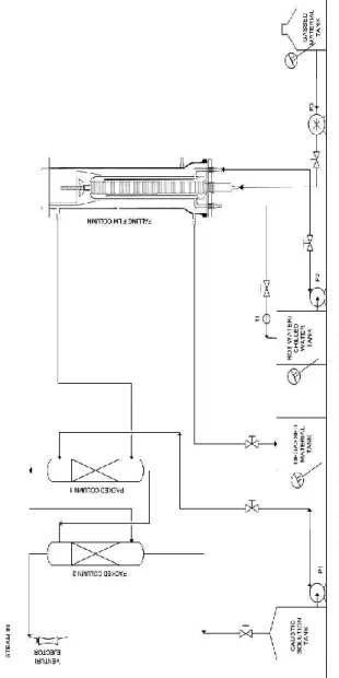
Fig. 2. Schematic diagram of experimental setup for desorption in falling film column.
III. PROCEDURE
A. Normal Start-Up
1) Start vent scrubber attached with the falling film column. Ensure low pressure (15 x10-3-50x10-3 m H2O) in scrubber lines and enough caustic solution present in scrubber tank having pH value above 10.0.
2) Start hot water circulation (pump P2) into utility connection (333-363 °K depending upon the boiling point of the liquid). In case of temperature sensitive liquids, normal water circulation is required.
3) Start circulating liquid to be degassed into the reactor through coils at a rate of 0.25x10⁻⁶ -0.33x10⁻⁶m3/s by using peristaltic pump (P3).
4) Ensure that liquid is distributed uniformly over the hot surface.
5) No dry pockets should form over the hot surface so that liquid is heated completely for the degasification to take place.
6) Collect the liquid and send sample for analysis. 7) Re-circulate the liquid till the desired level of degassing
is achieved.
B. Normal Shut-Down
1) Stop liquid circulation to the column.
2) Allow liquid to drain-out from the column completely. 3) Allow water to circulate for some time to remove free
gases from column completely.
4) Take sample to check the desire level of gas present in it.
C. Method of Analysis to determine Free HCl
1) Take 0.025 L of toluene.
2) Add 3-4 drops of Bromocresol solution.
3) Neutralize it with 0.1N NaOH solution. Stir it completely till colour changes to blue.
4) Add 1 ml of degassed liquid in it. Solution becomes colorless.
5) Titrate it with 0.1N NaOH solution till solution turns to blue. % wt. /vol. of HCl = B.R.Normality of NaOH solution3.65
D. Experimental Results
TABLE.I:EXPERIMENTAL RESULTS OF DESORPTION OF SOLUTE GAS FROM LIQUID FALLING FILM
IV. FALLING FILM AS ABSORBER
The present work was further extended for the preparation of chloroformates by treating gaseous phosgene with liquid 2-Ethyl Hexanol or Benzyl alcohol in Falling Film column.
A. Chemical Reaction
1) 2- Ethyl Hexyl Chloro Formate (2- EHCF) Chemical formula: C8H18O + COCl2 = 2-EHCF + HCl Mole Wt. (kg/kmole): 130.23 98.9 192.69 36.5 Δ Hr = -29.13 kJ/kg of 2-Ethyl Hexyl Chloro Formate
2) Benzyl Chloro Formate (BCF)
Chemical formula: C7H8O +COCl2 = BCF + HCl Mole Wt. (kg/kmole): 108.14 98.9 170.59 36.5 Δ Hr = -54.46 kJ/kg of Benzyl Chloro Formate
B. Experimental Results
TABLE-II:EXPERIMENTAL RESULTS OF ABSORPTION OF PHOSGENE GAS IN 2-ETHYL HEXANE IN FALLING FILM Flow rate
kg/s Reaction
Temp °K
% Purity by GC
Molar Yield Phosgene
(gas)
2-Ethyl Hexanol (liquid)
TABLE-III:EXPERIMENTAL RESULTS OF ABSORPTION OF PHOSGENE GAS IN BENZYL ALCOHOL IN FALLING FILM
Flow rate
kg/s ion React
Tem p °K % Pu rity by G C Molar Yield Phosgene (gas) Benzyl Alcohol
(Liquid)
2.17x10⁻⁴ 1.38x10⁻⁴ 269 94
.43 96.35
2.20x10⁻⁴ 1.40x10⁻⁴ 268 95
.3 97.21
2.17x10⁻⁴ 1.33x10⁻⁴ 270 95
.61 97.51
2.20x10⁻⁴ 1.40x10⁻⁴ 269 96
.57 98.2
2.20x10⁻⁴ 1.38x10⁻⁴ 269 95
.78 98.39
Chilled thin film of alcohols like Ethyl Hexanol or Benzyl Alcohol was falling down. Pure phosgene gas was passed through narrow passage of column, and allows reacting with alcohols to produce 2-Ethyl Hexyl Chloro Formate (2-EHCF) and Benzyl Chloro Formate (BCF) respectively. The reaction heat was removed by passing chilled brine solution in inner core of falling film column, were two pass of utility system Fig. (1) is very much useful for better heat removal.
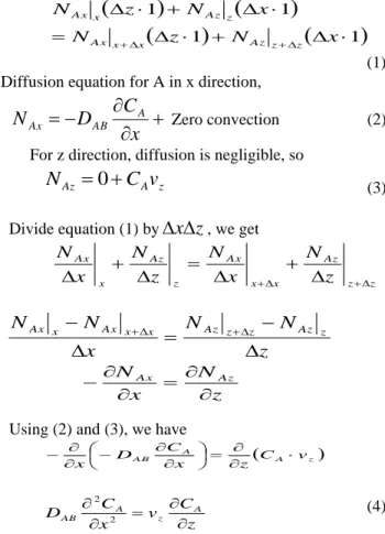
V. MATHEMATICAL MODELING
Here, we will consider mass transfer of solute A into a laminar falling film, which is important in wetted-wall columns, in developing theories to explain mass transfer in stagnant pockets of fluids and in turbulent mass transfer. The solute A in the gas is absorbed at the interface and then diffuses a distance into the liquid so that it has not penetrated the whole distance x= at the wall. At steady state the inlet concentration CA = 0. At a point z distance from the inlet, the concentration profile of CA is shown in figure.
Fig. 3.Velocity profile and concentration profile for diffusion of solute gas in liquid falling film.
Fig.4. Small element for mass balance for diffusion of solute gas in liquid falling film.
1
1
1 1
z N x
N x N z N z z Az x x Ax z Az x Ax (1) Diffusion equation for A in x direction,
x
C
D
N
Ax AB A Zero convection (2)For z direction, diffusion is negligible, so
N
Az
0
C
Av
z (3)Divide equation (1) by
x
z
, we getz z Az x x Ax z Az x Ax z N x N z N x N z N N x N N z Az z z Az x x Ax x Ax z N x
NAx Az
Using (2) and (3), we have
A z
A
A B C v
z x
C D
x
z C v x C D A z A AB 2 2 (4)
If the solute has penetrated only a short distance into the fluid i.e. short contact time.
z
v
z
t
Equation (4) becomes
z A A AB v z C x C D 2 2
t
C
x
C
D
A AAB
2 2 (5)Integrating equation (5) with boundary conditions,
CA = 0 at z = 0 CA = CA0 at x = 0 CA = 0 at x =
The solution should be in the form of f
C C
A A
0
where,
is dimensionless variablet D x AB 4 So, new variables are
2 "
2 2 0 2 f x x C C A A Equation (5) becomes, f"
2f'
0 With boundary condition, = 0 f 1
= f
0So, f '
C1e2 (First integration) 2 0 1 2 C d e C
f
(Second integration)
Applying boundary condition,
0 0 2 2 1 ) (
d e d e f=
0 2 21 e d
Put values,
t D x AA A B
O d e C C 4 0 2 2
1
t D x erf AB 4 1 z AB v z D x erf 4 1 z A B A A v z D x erf C C 4 0 (6)
We can apply equation (6) in desorption of phosgene/HCl gas from 2-EHCF in Falling Film Column.
So taking, z AB v z D x y 4 We have,
y erfc CCA A0 (7)
VI. FALLING FILM CALCULATION
We took example of desorption of free gases (i.e. phosgene or HCl) from 2-Ethyl Hexyl Chloro Formate (2-EHCF) product for falling film height sample calculation.
A. Estimation of Thin Film Thickness
Film Thickness (δ) Calculation:
3 3 gW Q (8) where:
μ = Viscosity of (2-EHCF) = 0.0174 kg/m s
Q = Volumetric Flow rate of 2-EHCF = 0.283x10⁻⁶ m3/s
ρ = Density of 2-EHCF = 981 kg/m3 g = gravitational acceleration = 9.81m/s2 d = diameter of column surface = 0.06 m W = Width of Film = πd = 3.14 x 6 = 0.1884 m
3 84 . 18 981 981 . 0 283 . 0 174 . 0 3 x x x x
= 2.00x10⁻⁴m
B. Estimation of Gas-Liquid Diffusivity Parameters
1/3 1/3
2 5 . 0 1.75 3 -* * T x 10
B A B A B A AB V V P D (9) where,T = Column temperature = 353 K MA = Mole. Weight of phosgene = 98.9 kg/kmole MB = Molecular weight of 2-EHCF = 192.5kg/kmole P = System (column) pressure = 0.996 atm ΣVA= Molar Volume of phosgene =57.9x10⁻⁶ m3/kmole ΣVB= Molar volume of 2-EHCF =196.22x10⁻⁴ m3/kmole
So,
1/3 1/3
2 5 . 01 .7 5 3 -) 22 . 196 ( ) 9 . 57 ( * 996 . 0 5 . 192 * 9 . 98 5 . 192 9 . 98 T x 10 AB D
= 0.0381x10⁻⁴m2/s
C. Estimation of Reynolds Number of Thin Falling Film
Liquid Side: d Q NRe (10) 174 . 0 6 1415 . 3 981 . 0 283 . 0 x x x
= 0.085 (Since this is less than 250, the flow of Film is in laminar regime)
As the flow is in laminar region, we take Sherwood Number from 0.2 to 0.3 for this kind of application.
D. Estimation of Gas Phase Mass Transfer Co-efficient
i AB Sh g D D N
K ( )*( ) (11)
6 38) (0.22)(0.0 = 0.14x10 -4 m/s
E. Estimation of the Reactor Length Needed to Reduce the Concentration of Phosgene
1) Based on Gas phase mass-transfer co-efficien
g o g i o L A Ao C D K D D u C C L * * * 4 ) ( * * )
( 2 2
(12)
CAo = Initial concentration of phosgene
4 % w/v = 4/98.9 = 40 kgmole/m3
CA = Final concentration of phosgene
0.1 % w/v = 0.1/98.9 = 1kgmole/m3
Di = Diameter of surface above which film forms
=0.06 6 m
t = Film Thickness (as calculated above) = 2.00x10⁻⁴ m
Do = Outer diameter of film = 2 (0.02) +6 = 0.0604 m
AC = Cross sectional area of film
2 2
4 Do Di
= 0.381x10⁻⁴ m2 ρ = Density of 2-EHCF = 981 kg/m3
m
= Mass Flow rate of 2-EHCF = 2.78x10⁻⁴ kg/sQ = Volumetric flow rate of 2-EHCF = 0.283x10⁻⁶ m3/s
381 . 0
283 . 0
C A Q
u = 0.00743 m/s
kg = Gas phase mass transfer co-efficient = 0.1410-4 m /s
Cg = Final concentration of phosgene gas
= 1 kgmole/m3
Putting values in equation (12)
001 . 0 04 . 6 0014 . 0 4
6 04 . 6 743 . 0 001 . 0 04 .
0 2 2
x x x
x x
L
= 4.16 m (Required) Actual Length = 1.00 m
So, we take 10 % excess of the required height which is (4.161.1) = 4.50 m.
We need approximately 4-5 circulations in actual column (Height = 1.00 m) to achieve desire concentration of gas
2) Based on basic Mathematical Process Modeling Input of liquid at the top – Output of liquid at the bottom = Accumulation
z
C
A
a
k
C
A
u
C
A
u
L
Az
L
Azz
L
A
L
(13) Divide the equation (13) by “Az”
We get,
L A L z z A L z A
L k a C
z C u z C
u
L A L A
L k a C
dz dC
u
00
A
A
C
C A
A z
L L
L
C dC a
k u dz
L L
A A L
a k
C C u Z
0
ln
(14) We have,
Z = Height of column
uL= Velocity of liquid film = 74.3x10⁻⁴ m/s
a = Interfacial area of film = 4950 m2/m3
CA0 = Initial concentration of gas at top
= 40 kgmole/m3
CA = Final concentration of gas at bottom
= 1 kgmole/m3
kL = Liquid phase m/t coefficient = 1.3x10⁻⁵ m/s
L = Liquid/gas hold-up = 0.1
1 . 0 * 5 . 49 * 3 3 . 1
001 . 0
04 . 0 ln * 743 . 0
E Z
Z = 4.3586 m
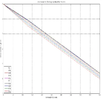
VII. SIMULATION RESULTS
Phosgene present in 2-EHCF was stripped off using Falling Film Column. Concentration of phosgene at different heights is obtained by using equation (7) with different film thickness.
Following are the parameter values required:
CA0 = Concentration of phosgene in 2-EHCF
= 50 kgmole/m3
DAB = Diffusivity of phosgene in 2-EHCF
= 0.03x10⁻⁴ m2/s
V = Velocity of film = 0.50 m/s
Z = Height of Falling Film Column = 5.00 m
2 2
dt C d dt
dC
V A A
AB
D
AB
D
V = Constant value for MATLAB program
= 215000 m-1
A simulation program written in MATLAB is shown below:
function pdex1 m = 0;
x = linspace(0,0.2,10); z = linspace(0,500,5);
sol= pdepe(m,@pdex1pde,@pdex1ic,@pdex1bc,x,z); % Extract the first solution component as u.
u = sol(:,:,1); surf(x,z,u) title('.')
xlabel('film thickness x in cms') ylabel('Film height = z in cms') zlabel('concentration in gm/cc') figure
plot(z,u(:,:))
title('Concentration Vs. Film height at different film thickness')
legend('0.2','0.18','0.16','0.14','0.12','0.1','0.08','0.06','0.04', '0.02',3)
legend();
xlabel('Film height = z in cms') ylabel('Concentration in gm/cc') grid on;
c = 2100; f = DuDx; s = 0;
% --- function u0 = pdex1ic(x)
u0 = 5;
% --- function [pl,ql,pr,qr]
= pdex1bc (xl,ul,xr,ur,z) pl = 0.02;
ql = 5; pr = 0.2; qr = 0.05; clc
From simulated data reveals fig. 5 and 6 it appears that there is a significant change in concentration of dissolved gas with respect to column height at different film thickness.
Fig. 5. Effect of concentration vs. film height at different film thickness.
Fig .6. Effect of concentration vs. film height at different film thickness in 3 dimensional view/ Surface Model.
VIII. CONCLUSION
Falling Film Column which is used as a reactor for gas-liquid reaction or as an absorber to dissolve gas in liquid is designed here to remove dissolved gases from liquid falling film. Model proposed in this paper is found useful in
calculating length of the falling film desorber require to strip off dissolved gases from liquid falling film. Model is proposed to determine the variation of concentration of solute gas in liquid film with height of column. Length, diameter, liquid film thickness and other parameters calculated theoretically is nearly same as obtained from experiments. Length calculated based on Gas-phase mass transfer coefficient and Mathematical Process Model is practically same. The same model is useful to calculate the rate of change of concentration of solute gas with height at different liquid film thicknesses.
IX. NOMENCLATURE
a = Interfacial area of film
A, AC = Cross-section area of film
CA0 = Concentration of A at the gas-liquid interface CA = Concentration of A within film
Cg = Final concentration of phosgene gas Di = Diameter of surface above which film forms
Do = Outer diameter of film
g = Gravitational acceleration
kg = Gas phase mass transfer co-efficient
kL = Liquid phase mass-transfer coefficient L = Length of the column
*
m = Mass Flow rate of liquid film
MA = Molecular weight of phosgene MB = Molecular weight of liquid film
NAx = Molar flux of component A in x direction P = System (column) pressure
Q = Volumetric Flow rate of liquid film t = Time
T = Column temperature
u = Velocity of liquid film
uL = Velocity of liquid film
vz = Velocity of liquid in z direction
ΣVA = Molar Volume of phosgene
ΣVB = Molar volume of liquid film
W = Width of Film
z =Differential height
Z = Height of column
d
Q
Number, Reynolds
NRe
AB i g
D D k
Number, Sherwood
NSh
Greek Symbols:
L = Liquid/Gas hold-up
δ = Film thickness
t D
x
AB
4 variable, ess
Dimensionl ç
μ = Viscosity of liquid film ρ = Density of liquid film
X. ACKNOWLEDGEMENT
guidance and support in compiling simulation program in MATLAB.
REFERENCES
[1] K. K. A, Pant and V. K Srivastava, Department of Chemical Engineering, Indian Institute of Technology, New Delhi.
[2] P. H Nielsen and J.V illadsen, Chemical Engineering Science 38 91439-1454. 1983.
[3] F. I. Talensand Alesson, Chemical Engineering Science 54 1871-1881.1999.
[4] Z. F. Xu, B. C Khoo, and N. E. Wijeysundera, Chemical Engineering Science 63 .2559-2575. 2008
[5] S. Banerjee, E. Rhodes, and D. S. Scott, Chemical Engineering Science
22, 43-48.1967.
[6] I. Fujita and E. Hihara, International Journal of Heat and Mass Transfer, 48, 2779-2786.2005.