SYNTHESIS & CHARACTERIZATION OF DEFECTS IN COATINGS AND THE DEGRADATION OF POLYMERIC MATERIALS
Ahmed-Rufai A. Ibrahim
A dissertation submitted to the faculty at the University of North Carolina at Chapel Hill in partial fulfillment of the requirements for the degree of Doctor of Philosophy in the Department
of Chemistry in the College of Arts and Sciences.
Chapel Hill 2017
Approved by:
Valerie Sheares Ashby Frank A. Leibfarth Wei You
© 2017
ABSTRACT
Ahmed-Rufai Ibrahim: Synthesis & Characterization of Film Defects in Coatings and Degradation of Polymeric Materials
(Under the direction of Valerie Sheares Ashby and Frank A. Leibfarth)
The field of macromolecular science has explored the ability of invoking high degrees of functionality to increase the applications in which materials may be utilized. In doing so, new characterization methodologies are necessary to better qualify and quantify their abilities and understand the dynamics behind their novel performance. This dissertation describes both of these areas, including the development of characterization methods for understudied biopolymers and emulsiproduced latexes, as well as the synthesis of novel polymers for achieving on-demand, segmented material depolymerization.
In Chapter 2, a method was developed for investigating the role of different constituents of an acrylic coating in creating film defects. The defect of film sag was studied utilizing an electron paramagnetic resonance (EPR) spin probe. The probe allowed the curing process of a coating to be surveyed and how the binder of the coating responds to coalescence. By doing this for both horizontal and vertical orientations, the sag film defect was observed by a variation in polarity of the spin probe. This polarity was evident in the spectra of the probe and its shift in polarity was quantified over time.
triggers investigated were pH and heat, due to their relevance and abundance of use in biological applications. The synthesized polymers were able to be depolymerized to their monomeric parent molecules discriminately based on the stimulus which the copolymer was exposed to. Various characterization methods were utilized to ensure the kinetics of depolymerization, as well which material was depolymerized, could be controlled. To investigate the viability of this system in drug delivery, biologically relevant copolymers were synthesized to be incorporated in multi-dye possessing polymersomes capable of on-demand release of said dyes in response to orthogonal stimuli.
Chapter 4 elucidates a method developed for the improvement of mucin characterization. Mucins are the macromolecules which make up mucus. The abundance of various mucins
ACKNOWLEDGEMENTS
I would like to start by thanking my mentor and advisor, Dr. Valerie Sheares Ashby. Your belief in me and eagerness for furthering scientific understanding in the field of polymers served as continued motivation for me. Seeing all that you have accomplished has steadily inspired me throughout graduate school. I also would like to thank my committee members, especially Dr. Frank Leibfarth and Dr. Wei You, for their support during courses, and whenever I needed assistance with my research. With regard to my time in the Forbes group, I would like to thank Dr. Malcolm D. E. Forbes for helping me think outside of the box to solve scientific problems. I also want to thank Dave Zigler, Soo Sim, Lauren Jaroch, Alex Brugh, Ian Mackenzie, and Anginelle Alabanza for the friendship and guidance through Electron
Paramagnetic Resonance spectroscopic methods. I would like to thank the last members of the Ashby lab (Katelyn Houston, Sarah Turner, and Annie Jackson) for the helpful conversations with research and assistance along the way. I must also thank Reggie Singleton with Fisher Scientific for aiding me with chemical and instrumentation purchases, and obtaining research needs during grant restructuring.
TABLE OF CONTENTS
LIST OF TABLES ………...xiv
LIST OF SCHEMES ……….xv
LIST OF FIGURES ………..xvi
LIST OF ABBREVIATIONS AND SYMBOLS ………...xix
CHAPTER 1: INTRODUCTION TO SYNTHESIS & CHARACTERIZATION OF DEFECTS IN COATINGS AND DEPOLYMERIZATION IN POLYMERIC MATERIALS………...………1
1.1 Overview………1
1.2 Introduction to Defects in Coatings………...1
1.2.1 Surface Defects in Coatings………1
1.2.1.a Craters ………2
1.2.1.b Air Entrapment………3
1.2.1.c Sag …..………4
1.2.2 Theory of Sag ……….5
1.2.3 Methods of Studying Sag in Coatings ………...7
1.2.4 Research Objectives ……….10
1.3 Degradable Polymers ………..12
1.3.1 Degradation in Materials ………..12
1.3.1.a Stimuli-Responsive Polymers ………..13
1.3.2 Self-Immolative Polymers ………...17
1.3.2.a Enzyme-triggered depolymerization ……….19
1.3.2.b Acid/Base-triggered depolymerization………..20
1.3.2.c Photo-triggered depolymerization………..21
1.3.3 Research Objectives………..22
1.4 Mucin Characterization ………...25
1.4.1 Overview of Mucins ………25
1.4.1.a Mechanisms of Mucociliary Clearance ………25
1.4.1.b Chemical Structure of Mucus ………...25
1.4.2 Mucin Overexpression in Diseases ………..26
1.4.2.a Asthma ………..27
1.4.2.b Chronic Obstructive Pulmonary Disease (COPD)……….28
1.4.2.c Cystic Fibrosis (CF) ………..29
1.4.3 Common Approaches Toward Mucolysis ………...32
1.4.3.a Non-destructive Mucolysis ………...32
1.4.3.b Destructive Mucolysis ………..32
1.4.4 Characterization of Mucins ………..33
1.4.4.a RT-PCR ……….33
1.4.4.b Rheology ………...33
1.4.4.c Mass Spectrometry ………34
1.4.4.d Western Blot ……….34
1.4.5 Research Objectives………..34
CHAPTER 2: EPR SPIN PROBE INVESTIGATION OF THE SAG SURFACE DEFECT IN ACRYLIC COATINGS DURING
COALESCENCE ...………...………...48
2.1 Introduction………..48
2.2 Experimental ………...51
2.2.1 Materials ………...51
2.2.2 EPR Spectroscopy ………51
2.2.3 Sample Preparation ………...51
2.3 Results and Discussion ………52
2.3.1 Drying on Vertical Substrates ………...52
2.3.2. Vertical vs. Horizontal Drying ………54
2.3.3 Photo-induced Curing ………...55
2.4 Conclusions ……….57
REFERENCES ………..59
CHAPTER 3: TRIGGERED DEPOLYMERIZATION OF POLYURETHANE-BASED MATERIALS IN RESPONSE TO ORTHOGONAL STIMULI ………...……...60
3.1 Introduction ……….60
3.2 Experimental ………...64
3.2.1 Materials and Methods ……….64
3.2.2 Synthetic Procedures ………65
3.2.2.a Synthesis of (Hydroxypentyl)phenylcarbamate (1) ………...65
3.2.2.b Synthesis of Benzyl-4-(hydroxymethyl)phenyl carbamate (2) ……….65
3.2.2.d Synthesis of Poly[benzyl-4-(hydroxymethyl)
phenylcarbamate] (4)……….66
3.2.2.e Synthesis of Poly[(hydroxypentyl)phenyl carbamate] (5) ………..….67
3.2.2.f Synthesis of Poly[4,4’-methylenebis(phenyl isocyanate)-alt-1,4 -butanediol](PMDIBD)………...………67
3.2.2.g Synthesis of Poly(phthalaldehyde)-b-poly[benzyl-4- (hydroxymethyl)phenylcarbamate] (6) ………...……..68
3.2.2.h Synthesis of 3-Azidopropanol (7) ………...……..69
3.2.2.i Synthesis of 2-(Dodecylthiocarbonothioyl thio) propionic acid chloride (8)………...…….69
3.2.2.j Synthesis of 2-(Dodecylthiocarbonothioyl thio)propionic acid 3-Azidopropyl ester (9)………...……...70
3.2.2.k Synthesis of Azide-bearing Poly[poly(ethylene glycol)methacrylate] (10)………...70
3.2.2.l Synthesis of Benzyl-4-propargylether(phenyl carbamate) (11)………..…71
3.2.2.m Synthesis of Alkyne-bearing Poly[benzyl-4-hydroxy methyl(phenylcarbamate)] (12) ………71
3.2.2.h Film preparation of 4 ………..……..72
3.3 Results and Discussion ………...………72
3.3.1 Polyurethane synthesis and characterization ………...72
3.3.1.a Synthesis of 4, 5, and PMDIBD polyurethanes ………....72
3.3.1.b pH-induced depolymerization of 4 and PMDIBD ………....75
3.3.2 Polyacetal synthesis and characterization ………....78
3.3.2. a Synthesis of polyacetal 3 ………..78
3.3.3 Multi-responsive block copolymer synthesis and
characterization ………...80
3.3.3.a Synthesis of 6 ………...……….80
3.3.3.b Depolymerization studies of 6 ………...……...81
3.4 Development of Multi-drug Releasing Polymersomes ………..…….87
3.4.1 Synthesis of Amphiphilic Diblock Copolymer for Multi-drug Release from Polymerosomes ………..…..89
3.4.1.a Synthesis of Hyprohilic block 10 ………..89
3.4.1.b Synthesis of Hydrophobic block 12 ………...…...90
3.4.1.c Future Directions ………...91
3.5 Conclusions ……….92
REFERENCES ………...………..94
CHAPTER 4: CHARACTERIZATION OF MUCINS TO AID THE DEVELOPMENT OF MUCOLYTIC AGENTS …………...………..97
4.1 Introduction ………...97
4.2 Experimental ………...99
4.2.1 Materials ………...………...99
4.2.2 GPC ………100
4.2.2.a GPC of Salivary Mucins ………...………..100
4.2.2.b GPC of High Molecular Weight Mucins …..………..100
4.2.3 Mucin Sample Preparation ………...………..100
4.2.3.a Saliva Samples ………...……….100
4.2.3.b Human Bronchial Epithelial (HBE) mucus samples ………101
4.3.1 Characterization of Salivary Mucins ………..101
4.3.1.a Optimized Spectrum of Salivary Mucins ……….101
4.3.1.b Denaturation Study of Mucins ……….103
4.3.2 Characterization of High Molecular Weight Mucins ………..104
4.4 Conclusions. ………..106
REFERENCES ………107
APPENDIX A: SUPPLEMENTARY INFORMATION FOR CHAPTER 2 ………109
APPENDIX B: SUPPLEMENTARY INFORMATION FOR CHAPTER 3 ……….129
LIST OF TABLES
Table 1.1 Common biopolymers utilized in various biomedical applications ……….16
Table 1.2 Mucin gene classifications and the associated MUC genes ……….26
Table 1.3 Common symptoms of CF at different stages of life ………...31
Table 3.1 Properties of synthesized polyurethanes ………..75
Table 3.2 GPC Data of pH-induced Depolymerization ………...76
LIST OF SCHEMES
Scheme 1.1 Reduction of disulfide bond-containing polymers ………15 Scheme 1.2 Scheme of the self-immolative spacer developed by
Katzenellenbogen in 1981 ………...…..18 Scheme 1.3 Common trigger for depolymerization upon exposure to
a Penicillin G Amidase stimulus………..………..19 Scheme 1.4 Boc and Fmoc chemical structures and common triggers
(Excess of acid and piperidine for Boc and Fmoc respectively) for their
cleavage………...20 Scheme 1.5 UV and NIR-responsive triggers for depolymerization in SIPs………21 Scheme 3.1 Synthetic procedure for producing phenyl carbamate-containing
monomers………...73
Scheme 3.2 Synthetic procedure for 3, 4, the AB type monomer control, 5,
and polyacetal-block-polyurethane copolymers. ……….……….74
Scheme 3.3 Formation of amphiphilic polymer through Copper catalyzed
LIST OF FIGURES
Figure 1.1 Illustration of cratering and the film flow at the defect ………3
Figure 1.2 Illustration of the uneven film caused by sag ………...4
Figure 1.3 Relevant forces for the curing of Newtonian coatings ……….6
Figure 1.4 Plot of common fluid property profiles ………6
Figure 1.5 Illustration of the SALSA technique (ridges on the substrate not shown to scale)12………9
Figure 1.6 A coating doped with a nitroxide spin probe as a basis for viewing sag with EPR ………...…11
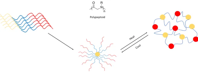
Figure 1.7 Illustration of Polypeptoid-based materials undergoing phase transitions utilizing heating and cooling. ………..………..………..13
Figure 1.8 Illustration of phase transition of poly(N-isopropyl acrylamide (PNIPAM) above its LCST ……….…….……….14
Figure 1.9 Illustration of release of a micelle core upon exposure to HIFU……….15
Figure 1.10 Illustration of self-immolative polymers and their potential triggers ………...18
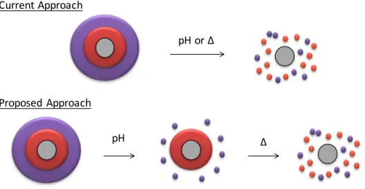
Figure 1.11 Depiction of current approaches in stimuli-responsive depolymerization in contrast to the proposed method……….………..23
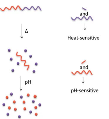
Figure 1.12 Controlled polymer depolymerization for the complete metabolism of copolymer systems in the on-demand response to orthogonal stimuli ………….……….…...24
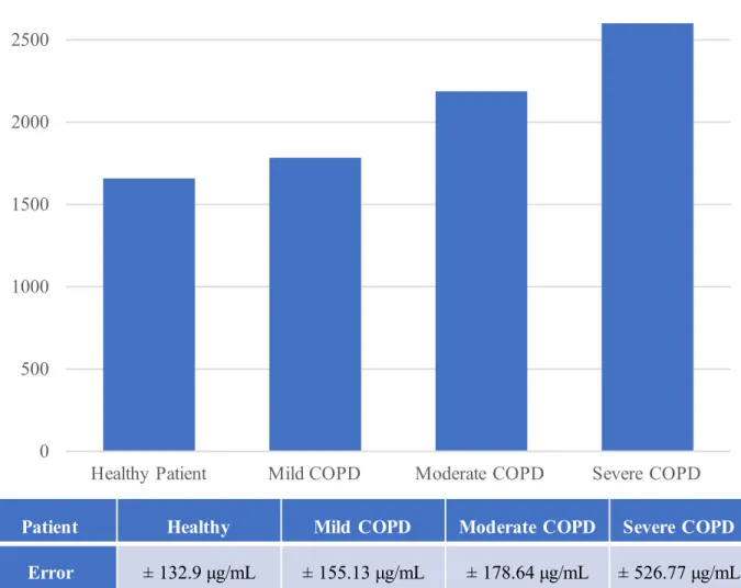
Figure 1.13 Total mucin concentration data of COPD patients at different stages………..29
Figure 1.14 Laser scanning confocal micrograph of normal mucus (A) and sputum of a CF patient (B). ………...…………30
Figure 2.2 A coating doped with a nitroxide spin probe as a basis for
viewing sag with EPR………50 Figure 2.3 The film curing process in a vertical drying geometry over
one hour as observed by spin probe EPR (left) and the integration of high
field hyperfine line and its transition over the first 20 minutes of drying (right)………...……...53 Figure 2.4 EPR spectra showing the variation in drying of a polymer
film based on the position of the film and substrate inside the EPR resonator. Left: only the bottom portion of the sample is inside the resonator.
Right: only the top portion of the sample is inside. ………..……54 Figure 2.5 EPR spectra showing an architectural coating drying in horizontal
and vertical geometries ……….55 Figure 2.6 EPR spectra showing the effects of UV light exposure on the
nitroxide radical ………....56 Figure 3.1 Controlled polymer depolymerization for the complete
depolymerization of a diblock copolymer system (A) and the depolymerization
products of the utilized pH-triggered and heat-triggered blocks (B). ……….………..62 Figure 3.2 Film depolymerization of 47.5k in an acidic solution.
A) Initial 47.5k film segment, B) Control 47.5k film segment which does not possess the Boc group end cap after 60 days of exposure. C) 47.5k film
segment possessing the Boc group end cap after 60 days of exposure………..77 Fig. 3.3 1H-NMR Data of o-phthalaldehyde monomer formation over
time (A), plot of depolymerization of 3 over time based on 1H NMR data (B)
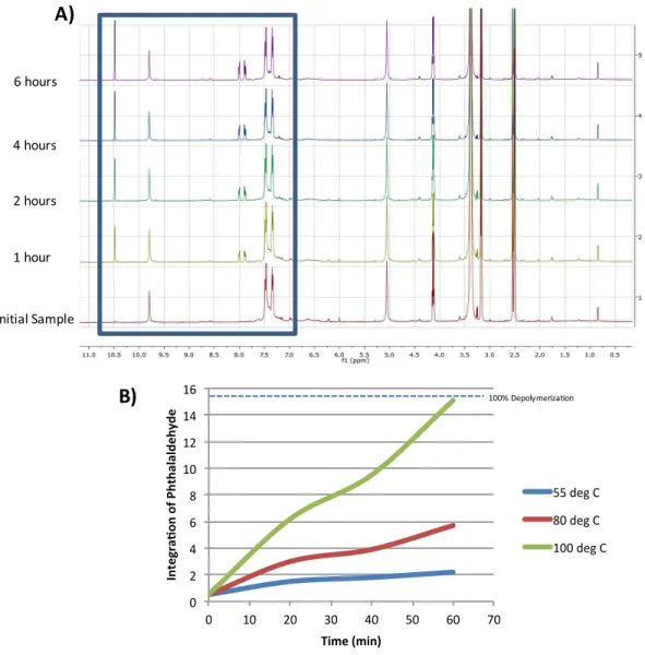
and plot of controlled depolymerization of 3 based on 1H NMR data (C) ………...79 Figure 3.4 Time-dependent NMR spectra of 612k after being exposed to
various temperatures showing the growth of the o-phthalaldehyde monomer (A) and the kinetics of monomer formation for the different temperatures
assessed (B). ……….…….82 Figure 3.5 ATR-IR spectra of 612k after being exposed to acidic conditions
(red) and elevated temperature (green) and being compared to the control
copolymer (blue) ……….……..84 Figure 3.6 GPC spectra and acquired GPC data for 612k after being exposed
to an acidic environment and elevated temperature ……….…….86 Figure 3.7 Illustration of Polymersome formation using amphiphilic blocks
Figure 4.1 GPC spectrum of salivary mucins in HPLC H2O and calculated
LIST OF ABBREVIATIONS AND SYMBOLS
% percent
degrees Celsius
± plus-or-minus
< > average
α angle of inclination
Δ heat
δ chemical shift
νo surface velocity of flow
µL microliter
µm micrometer
η viscosity
η(t) time-dependent viscosity Ψ∞ total film flow
! density
Ax hyperfine interaction along the x-axis Ay hyperfine interaction along the y-axis Az hyperfine interaction along the z-axis Azz high-field hyperfine interaction
b block
BEGM bronchial epithelial growth medium
CaCO3 calcium carbonate CDCl3 deuterated chloroform CF cystic fibrosis
CFTR cystic fibrosis transmembrane conductance regulator cm-1 wavenumbers
CO2 carbon dioxide
COPD chronic obstructive pulmonary disorder CTA chain transfer agent
CuAAC copper catalyzed azide/alkyne cycloaddition CW continuous wave
d doublet
DBTL dibutyltindilaurate dd doublet of doublets deg. degrees
DLS dynamic light scattering DMF N,N-dimethylformamide DMSO dimethylsulfoxide DNA deoxyribonucleic acid DNase deoxyribonuclease
FEV forced expiratory volume Fmoc fluorenylmethyloxycarbonyl FVC forced vital capacity
g gram, gravity
G gauss
g/mol gram per mole GHz gigahertz
GPC gel permeation chromatography
gx g-factor along the x-axis of contribution gy g-factor along the y-axis of contribution gz g-factor along the z-axis of contribution h(t) time-dependent change in film thickness H2O water
HBE human bronchial epithelial HCl hydrochloric acid
HIFU high intensity focused ultrasound
HPLC high performance liquid chromatography J coupling constant
k kilo
kDa kilodalton kHz kilohertz
L liter
LCST lower critical solution temperature
M molar
m multiplet
MALS multi-angle light scattering MCC mucociliary clearance MDa megadalton
MDI methylene diphenyl diisocyanate
mg milligram
MgSO4 magnesium sulfate MHz megahertz
min minute
mL milliliter mM millimolar mmol millimole
Mn number-average molecular weight mT millitesla
MUC# mucin gene (identification number) Mw weight-average molecular weight
N Nitrogen-bonded
NAC N-acetylcysteine NaHCO3 sodium bicarbonate NH4Cl ammonium chloride
NIR near-infrared
NMR nuclear magnetic resonance
O oxygen-bonded
o ortho
Pa pascal
PBHMPC poly[benzyl-4-hydroxymethyl(phenylcarbamate)] PBS phosphate buffered saline
PCL poly(caprolactone)
PCR polymerase chain reaction PDI polydispersity
PDLA poly(D-lactide) PDLLA poly(D,L-lactide) PDT photodynamic therapy PEG poly(ethylene glycol)
PEGMA poly(ethylene glycol)methacrylate PEO poly(ethylene oxide)
PF(t) time-related paint flow PGA poly(glycolic acid) pKa acid dissociation constant PLA poly(lactide)
PLGA poly(lactic-co-glycolic acid) PLLA poly(L-lactide)
PNIPAM poly(N-isopropylacrylamide) PPA poly(phthalaldehyde)
PPEGMA poly[poly(ethylene glycol)methacrylate] ppm parts per million
PS poly(styrene)
PSS poly(styrenesulfonate) PTFE poly(tetrafluoroethylene) q volume flow, quartet (NMR)
RAFT reversible addition-fragmentation chain-transfer RNA ribonucleic acid
RT-PCR reverse transcription polymerase chain reaction
s singlet
S∞ total amount of sag
SALSA sag and leveling surface analyzer SIP self-immolative polymer
SSEPR steady-state electron paramagnetic resonance
t triplet
TBS tert-butylsilane TBSCl tert-butylsilylchloride Tc ceiling temperature
TEMPO 2,2,6,6-Tetramethyl-1-piperidinyloxy tert tertiary
Tg glass transition temperature TGA thermogravimetric analysis THF tetrahydrofuran
TiO2 titanium (IV) dioxide TLC thin-layer chromatography tt triplet of triplet
UCST upper critical solution temperature UV ultraviolet
VOC volatile organic compound vWF von Willebrand Factor
W watt
CHAPTER 1: INTRODUCTION TO SYNTHESIS & CHARACTERIZATION OF DEFECTS IN COATINGS AND DEPOLYMERIZATION IN POLYMERIC
MATERIALS
1.1Overview
This dissertation describes the synthesis and characterization of film defects within acrylic-based coatings for optimizing formulation methods. It also describes the synthesis, characterization, and stimulus-dictated kinetics of selectively depolymerized diblock copolymers which respond to orthogonal stimuli on-demand. Section 1.2 reviews pertinent information regarding film defects, how they arise, their importance, the chemistry behind them, and current methods to qualify them. Section 1.3 provides detail on the background of purposely-degradable materials, their synthesis, and their applications. This work also investigates methods for
characterizing mucins for advancing the scientific understanding of these macromolecules. Section 1.4 offers insight on the field of mucins, current characterization techniques and their shortcomings, and drug development methodologies of mucolytic agents.
1.2 Introduction to Defects in Coatings 1.2.1 Surface Defects in Coatings
The post-World War II employment of emulsion polymerizations in the production of plastics has allowed for great advancement in latex coatings.1 Films are now capable of
barrier) are a few of many properties determined by the cured surface.2 Appearance, however, is the primary property which must be perfect to the end-users of most formulated paints.2 It is also the most difficult property to reproduce on a batch-to-batch basis.
Paints contain dispersions of multiple components, which must be formulated at optimal concentrations so that they complement each other’s performance before, during, and after application. In addition, the order in which these components are added during the
manufacturing process, and the processing conditions, must be ideal. A small lapse in the specificity of these three factors can cause film defects to occur on the surface of the cured product.3 Because coatings are initially liquids and become a solid film after being applied on a substrate, numerous factors in the application and curing process play a role in altering the surface of the coating as well. The application process can lead to defects based on the method, applicator used, and thickness of the applied wet film. During the curing process, environmental conditions and orientation of the substrate create variables that affect the rate of cure and the flow of the coating, which can also create defects in the cured film.
1.2.1.a Craters
Figure 1.1 Illustration of cratering and the film flow at the defect
1.2.1.b Air Entrapment
1.2.1.c Sag
As coating technologies move toward environmentally friendly formulations and reduce the amount of volatile organic compounds (VOCs) they contain, the typical concentration of solids in coatings has increased significantly. As a result, the most frequent film defect is the occurrence of sag. On an inclined substrate, an applied coating’s flow is used to create a level surface. The flow and leveling potentials of paints are determined by their rheology properties, the density of the coating, and the degree of inclination of the substrate. A coating which is not viscous enough to flow at a rate optimal for its curing kinetics will flow too fast and create a gradient in film thickness, growing in size as it travels downward as depicted in Fig. 1.2.
As evident by sag, a formulated paint which satisfies appearance on a horizontal
substrate may not necessarily produce satisfactory results on a vertical substrate, and vice versa. Though rheology modifiers and concentrations of solvents are the primary culprit from a
formulation standpoint, error during application and the environmental conditions of the cure are necessary to consider as well.4 Take for example applying paint using a paintbrush. By the natural motion of a stroke using a brush, maximum shear is applied at the midpoint of the stroke, and lessens as the brush reaches the bottom of the stroke until it is removed from the substrate. This creates an inherent ascent in film thickness as you move down the substrate. Formulators rely on the flow of the paint to level the coating as described previously, however, if the environment is one which promotes a rapid cure, sufficient flow cannot be achieved and sag occurs.
1.2.2 Theory of Sag
Figure 1.3 Relevant forces for the curing of Newtonian coatings
Newtonian liquids provide a good basis for understanding what factors play a role in the curing of coatings on a vertical substrate, but do not tell a complete story in modern coatings. Paints are ideally formulated to be shear thinning, that is, they flow better when stress is applied and exhibit high viscosity under no stress (Fig. 1.4). Such a rheology behavior is preferred so that sag can be minimized during curing for achieving optimal appearance and coating coverage of the substrate without sacrificing ease of application for the end-user.
Figure 1.4 Plot of common fluid property profiles Viscosity
Stress
Shear Thickening
Newtonian
Shear Thinning
(1)
(2)
Because the viscosity of the film changes during the curing process, the variation in wet film thickness and viscosity as a function of time must be considered. Orchard et al.7,8 and Overdiep9,10 studied this rigorously and determined that the total film flow, ψ∞, can be measured by the following equation:
ò
¥¥ = 0
3 ) ( ) ( dt t t h h y (4)
Though a change in film thickness during the curing process in liquid paints does occur as the solvent leaves the coating, it is marginal, thus h3(t) is relatively constant.
The inverse of the time-dependent viscosity, [η(t)-1],is regarded as the fluidity of the coating. The integration of the fluidity over the time period of the curing process results in the paint flow at time t, [PF(t)]. Using Eq. (4) in conjunction with the density of the coating and inherent force of gravity, the amount of sagging can be evaluated by;
¥
¥= y
a r 3 sin g S (5)
where α is the angle of inclination of the substrate. This means that sin (α) =1 for most traditional architectural substrates. The value of S∞ provides information on the amount of a coating that passes a fixed position on a sloped substrate.9,10
1.2.3 Methods of Studying Sag in Coatings
recommendations which typically involve an adjustment in concentrations of the rheology modifiers present. This approach is quick, but gives little information on the role of the many components within the coating. Because of this, only the rheology modifiers are manipulated, which can have a drastic effect on the end-use properties of the film as well as the shelf-life of the coating.11 Another disadvantage is that this reformulation must use a trial and error methodology.
The prevalence of rheometers and their use in understanding the curing properties of coatings began in the late 1980’s, and their use played an integral role in understanding rheology properties in the curing of films. The response of the coating to gradually increased shear and subsequent relaxation has been tied to the flow and leveling properties, as well as the potential for sag. The information generated does allow formulators to understand what film defects may occur upon application, but is limited by the model only being relevant for that particular base. A coating using a different polymeric binder or different pigment volume concentration will need to use a different model for understanding curing dynamics. In order to aid in this, coatings companies set specifications on the viscosity a paint should possess at certain levels of shear to create formulation databases.
Most recently developed is the use of the Sag and Leveling Surface Analyzer (SALSA) method, designed in 2006 by in the Bosma laboratory.12 This technique uses a sinusoidal applicator to create a coating on a substrate with a rippled surface. The wavelength and
Figure 1.5 Illustration of the SALSA technique (ridges on the substrate not shown to scale, used with permission from author)12
The apparatus is also equipped with a camera which detects the shift in gloss and records images as the coating dries. The data obtained from the shift in the shape of the surface as well as the gloss measurements gives information on the amount of sag which takes place for the coating. Similar to rheometry, this method allows a temperature dependence on flow to be realized as well by imposing a ramped heating environment during the curing process.
1.2.4 Research Objectives
Figure 1.6 A coating doped with a nitroxide spin probe as a basis for viewing sag with EPR
As shown in Fig. 1.6, a concentration gradient of spin probe is hypothesized to form as the coating flows and sag occurs. This can be measured by SSEPR by a change in the intensity of the nitroxide spectra. If said gradient is not evident with the horizontal samples, then it can be used as evidence for the existence of sag.
thickener-based spin probes, etc.) can be utilized in this same fashion to understand their dynamics during film coalescence and their stratification in the fully cured film.
1.3Degradable Polymers 1.3.1 Degradation in Materials
The purposeful destruction of materials has been used to invoke a multitude of properties on everyday polymers, and to create novel functionalities for innovative technologies. This class of materials are referred to as degradable polymers. They carry a specific set of properties that are gradually lost after exposure to a particular stimulus, and can also inherit new properties up on degradation. Based on their inherent chemistry and the degradation method, they provide the ability to degrade or depolymerize as a benefit to either the materials physical properties,
appearance, surface chemistry, or recyclability.16 This vast land of opportunity for the use of these materials has led researchers to challenge the status quo of materials and push their capabilities using degradation.
Though there are many opportunities for boosting the scientific knowledge of this field, the challenges of these materials cannot be overlooked. There is an ability to control the magnitude of degradation which takes place based on factors such as temperature, pH, polymer composition and structure, or percent crystallinity.17 However, increasing or decreasing the rate of degradation is not always as simple as modifying the chemistry of the monomer or increasing the magnitude of the stimulus. Another battle scientists face, and maybe the most important, is the ability to dictate the degradation products formed through the initial synthesis18. Full
must be able to be metabolized by enzymes or excreted. If not, their imposed toxicity can be life-threatening.19
1.3.1.a Stimuli-Responsive Polymers
Polymers which possess a trigger for stimulus-induced degradation have been created as a mechanism to combat random degradation of materials. In a random degradation event, a polymer chain could in theory be cleaved to half of its original size.20 Such an occurrence would drastically effect the physical properties of the material if a majority of the chains are degraded randomly, thus limiting its use in applications. Stimuli-responsive polymers can degrade to small molecules at controllable rates. A multitude of stimuli are able to be invoked into polymers to aid in recyclability and release of small molecules.21,22
Temperature-responsive polymers are of the highest studied. Recent work by Xuan and Zhang23showcases a series of polypeptoids which undergo thermoreversible sol-gel transitions. They utilize these transitions to encapsulate enzymes without affecting the enzymes activity or structure, giving their material interesting uses in tissue engineering applications.
Figure 1.7 Illustration of Polypeptoid-based materials undergoing phase transitions utilizing heating and cooling.
N R O
Another commonly exploited trait of thermoresponsive polymers is a phase transition at a lower critical solution temperature (LCST) or upper critical solution temperature (UCST) in aqueous solutions.24-34 Researchers utilize the phase transitions of these polymers to affect their miscibility, and can release and encapsulate various small molecules due to this. An example of this is in the work of Xu, Meng, and Zhong35, who prepared triblock copolymers consisting of poly(ethylene oxide)-b-poly(acrylic acid)-b-poly(N-isopropylacrylamide) to create
polymerosomes capable of encapsulating and releasing model proteins based on fluctuations of the solutions’ temperature. These polymers are not completely degradable but possess similar abilities due to the phase transitions they experience.
Figure 1.8 Illustration of phase transition of poly(N-isopropyl acrylamide) (PNIPAM) above its LCST
Polymers with disulfide bond linkages between monomers are a useable system for small molecule release using reducing agents. These reduction-responsive polymers possess the ability
Heat > LCST
to degrade through disulfide bond reduction and re-polymerize once oxidized.36 Glutathione and N-acetyl cysteine are common agents used to create reducing conditions for these systems, however, their efficiency is questionable due to the recombinative nature of free thiols.37-41 This is a common degradation method in natural biopolymers due to their many disulfide linkages.
Scheme 1.1 Reduction of disulfide bond-containing polymers
The subset of stimuli-responsive materials which has gained much interest in the last decade is field responsive polymers. This includes photo-42-63, electro-64-91, magnetic-92-97, and ultrasound-sensitive98-110 materials. In the case of ultrasound-responsive polymers, ultrasounds are used to create gel-to-gel transitions, cleave bonds, and increase solubility. Zhang et. al.111 used this ability to release hydrophobic Nile Red dye from the core of poly(ethylene oxide) -block- poly(lactic acid) (PEO-b-PLA) micelles with a high-intensity focused ultrasound (HIFU) created disturbance to the micellar structure. HIFU gained clearance for clinical-use in the 1990’s and is an ideal method of triggering ultrasound-responsive materials due to its tunability and low intensity being tolerable for humans.
Figure 1.9 Illustration of release of a micelle core upon exposure to HIFU
R
SH
S
R
S n
Reducing Agent
n
Micelle
1.3.1.b Biodegradable Polymers
The field of biomaterials has been most active in working to utilize degradable polymers. Biological scientists have created numerous combinations of polymers for tissue engineering of scaffolds which can assist in tissue repair and degrade away once full healing has occurred, vaccines with controlled released to optimize efficacy, hydrogels to assist in superficial healing of wounds, and drug delivery vesicles which provide specificity to delivery medications only to specific cells or organs.112-116 Table 1.1 displays a list of the common biopolymers which can degrade in response to various stimuli.
Table 1.1 Common biopolymers utilized in various biomedical applications
Name Polymer Structure
Poly(ethylene glycol) (PEG)
Poly(lactic acid) (PLA)
Poly(D-lactic acid) (PDLA)
Poly(L-lactic acid) (PLLA)
Poly(D,L-lactic acid) (PDLLA) Racemic mixture of PDLA and PLLA
Poly(caprolactone) (PCL)
Poly(glycolic acid) (PGA)
Poly(lactic-co-glycolic acid) (PLGA)
In order to avoid the harmful degradation by-products which can accumulate due to partial degradation, researchers have worked to synthesize materials which depolymerize instead of degrade. This involves the polymer degrading to the parent monomer. To do so, the
depolymerization reaction must be favored, which involves the entropic contribution to the free energy of polymerization outweighing the enthalpic contribution.117 Scientists are creating this shift by forcing the polymer to respond to a specific stimulus. Stimulus-induced
depolymerization has tremendous implications for a number of fields, including coatings, medicine, and waste management.17
1.3.2 Self-Immolative Polymers
Towards creating a systematic approach for depolymerizing materials, a class of
polymers titled self-immolative polymers (SIPs) were developed in 2003.118 These polymers are kinetically stable and possess a dormant chain end that responds to a specific stimulus by
Figure 1.10 Illustration of self-immolative polymers and their potential triggers
Though the polymers were only developed less than two decades ago, they are derived from the work of Katzenellenbogen, who in 1981 developed a self-immolative phenyl carbamate spacer that possessed a trypsin-responsive trigger and a small output molecule (Scheme 1.2).120 It was not until 2001 that the Scheeren lab utilized these spacers and turned them into oligomers for drug-releasing self-immolative scaffolds, and then self-immolative polymers along with the Shabat and McGrath laboratories in 2003.121-123
Scheme 1.2 Scheme of the self-immolative spacer developed by Katzenellenbogen in 1981
Stimuli Light Acid/Base Heat Enzyme Stimulus-Responsive Trigger Self-Immolative Monomer
Small Molecule Output
O O NH NH3 O HN O O H
N NO2
H2N
O O
H
N NO2
OH H2N
NO2
H2N
Trypsin H2O
-CO2
Trigger
Spacer
This class of polymers can typically be obtained in a one-pot synthesis which eases their manufacturing for mass production. Small molecules can be bound to functionalities along the back bone, which can be released for healing and drug delivery applications. These polymers can also be synthesized in a multitude of mechanisms, ranging from step-growth, to emulsion, to living polymerizations to control their properties.124-126
1.3.2.a Enzyme-triggered depolymerization
Enzyme-mediated degradation of materials is a highly-sought feature due to its
implications in biological systems and the abundance of information on enzyme activities and kinetics afford tunability for initiating degradation. Enzymes have successfully triggered depolymerization events in SIPs127-134 and were of the first triggers studied in this class of polymers.135, 136 Researchers have been able to utilize foreign137,138 and native139 biological agents to trigger continuous elimination events in human physiology. Though optimization is still necessary for the full potential of enzyme-triggered depolymerization to be realized in SIPs, the goal is for such materials to be used in very complex biological systems where specificity is key for success.
Scheme 1.3 Common trigger for depolymerization upon exposure to a Penicillin G Amidase stimulus
N
H
O
R
1.3.2.b Acid/Base-triggered depolymerization
A material’s ability to respond to the pH of its environment is another important feature in biological applications which scientists aim to manipulate for optimal degradation kinetics and small molecule delivery.128,132,134,140 Most reviewed for their abilities to respond to acidic and basic conditions are tert-butoxycarbonyl (Boc) and fluorenylmethyloxycarbonyl (Fmoc) protecting groups respectively. They allow facile depolymerization in SIP systems and the kinetics are typically controlled by the concentration and strength of the acid or base used.141,142 Acid/base triggers are readily available and are easily attached to polymers of various
functionalities.
Scheme 1.4 Boc and Fmoc chemical structures and common triggers (Excess of acid and piperidine for Boc and Fmoc respectively) for their cleavage
1.3.2.c Photo-triggered depolymerization
Photomedicine has been a field of interest to researchers due to its potential for non-invasive methods and expedited results. It is the study of how light can be used to advance medical treatments and procedures.143 Recent advancements in current photomedicine treatments such as photodynamic therapy (PDT) and laser-assisted in situ keratomileusis (LASIK) have caused scientists to further explore how current knowledge in photochemistry can be employed for creating novel medical as well as industrial products. In the realm of SIPs, the ultraviolet (UV) and near-infrared (NIR) triggers of nitrobenzyl carbamates144 and bromocoumarins145 respectively, have shown the ability to cleave in response to the appropriate wavelength of light. NIR triggers are of special interest due to NIR light’s capacity to penetrate the stratum corneum at low intensities145. Such findings of remote activation of depolymerization show promise for in vivo applications of SIPs and may lead to the ability for the spatiotemporal control of drug release.
Scheme 1.5 UV and NIR-responsive triggers for depolymerization in SIPs
O O O O N R NO2 O O HO Br O O N R
O
O
N
R
UV light NIR lighto-nitrobenzyl carbamate
Interesting results in the space have lead researchers to push further in attempts to reduce the environmental impact of materials. Enhancing recyclability is one of the major goals of global manufacturing sites to align with today’s ideals of creating a sustainable future. Efforts in the synthesis of stimuli-responsive cross-linked and thermoset materials have gained momentum in the last five years. The Long laboratory at Virginia Tech reported in 2014 a recyclable low-temperature thermoset that is able to reverse cross-links and revert back to its monomers upon the addition of a pH=2 aqueous solution.146 The polymer contains a triazine heterocycle, which provides thermal stability and increases the thermal glass transition temperature (Tg). This work is promising for the future of enabling an on-demand destruction of high performance polymers. 1.3.3 Research Objectives
Recent discoveries utilizing SIPs have allowed for polymers to be utilized in applications which many would think inconceivable decades ago. However, the work completed thus far is common in the sense that the entire material is affected by the exposure of its triggering
stimulus, whether it be responsive to one or multiple. In this report, we propose the synthesis of materials capable of an on-demand, selective depolymerization (Fig. 1.11). These novel
Figure 1.11 Depiction of current approaches in stimuli-responsive depolymerization in contrast to the proposed method
Colloidal dispersions provide the ability to deliver a drug or healing agent in a multitude of applications. By incorporating a copolymer in the design of these particles capable of
depolymerizing in a controlled manner in response to two orthogonal stimuli, efficiency of delivery of the micelle core can be increased while solving natural issues. For example, adverse weather has had harsh effects on the agricultural industry. Crops can be treated using
nanoparticles which systematically depolymerize by heat and light, relying on the prevalence of sunlight to deliver a growth aid or pesticide during cold weather.147 Also, as previously
discussed for biomedical applications, biocompatible vesicles must be able to exit the body or be metabolized when delivering drugs or healing bodily tissues without toxic effects. There are currently very few FDA-approved depolymerizable biomaterials used for such medical applications. Topical analgesics are an example of how drug delivery could benefit from the aforementioned particles. They have limited efficacy and very short durations of action. Being a superficial treatment, the abundance of light can be used to initiate a controlled, extended release of medication and ease the troubles of topical analgesic formulation with the permeability of the
pH Δ
pH or Δ Current Approach
stratum corneum. Such a method of delivery would increase the efficacy of these topical
treatments while reducing the need for oral medications, which have toxic side effects.105,107,148 Bearing the most environmental relevance is the implication this study has for recyclable
materials. The ability for a material to depolymerize completely to its parent monomer in a facile manner simplifies the recycling process and aids greatly in material renewability.
To obtain a selective depolymerization, proposed is the synthesis of a copolymer of SIPs. Because of the facile and rapid depolymerization of this class of materials with high selectivity for certain stimuli based on the chemistry of the end cap, these polymers are ideal for these studies in creating a controlled, yet selective, on-demand depolymerization. This is further illustrated in Figure 1.12.
Figure 1.12 Controlled polymer depolymerization for the complete metabolism of copolymer systems in the on-demand response to orthogonal stimuli
Δ
pH
Heat-sensitive
pH-sensitive and
1.4 Mucin Characterization 1.4.1 Overview of Mucins
Naturally produced defense mechanisms are common in biology, allowing living organisms to battle foreign, harmful objects to reduce the magnitude of detriment they may impose. In the lungs, the most important of such natural defenses is mucus clearance. 1.4.1.a Mechanisms of Mucociliary Clearance
Mucus lines the epithelial surface of the nasal cavity, mouth, esophagus, trachea, and lungs to act as the first line of defense in stopping harmful particulates and pathogens from adsorption through the epithelial membrane.149-151 Mucus also possesses enzymes which are capable of breaking down and detoxifying molecules so that they may be easily discarded. The human body continuously removes mucus via mucociliary clearance (MCC).152 This involves the cilia along epithelial cells “beating” at a frequency which enables removal of mucus with
pathogens trapped in its gel matrix. As mucus is cleared, mucus is continuously secreted as well to ensure constant protection. Mucus is a viscoelastic layer, and the ability for cilia to clear mucus through MCC is dependent on a few factors, including the level of hydration of the mucus gel and the mucus type.153
1.4.1.b Chemical Structure of Mucus
In humans, mucin genes are termed “MUC#”, the number being related to the order in which they were discovered. There are three major families which these genes are classified into. These are displayed in Table 1.2.
Mucin Gene Family Secreted, Gel-Forming Secreted, Non-gel Forming Membrane-associated (Cellular receptors) MUC gene Associated MUC5AC MUC5B MUC2 MUC3 MUC19 MUC7 MUC1 MUC4 MUC11 MUC13 MUC15 MUC20 Table 1.2 Mucin gene classifications and the associated MUC genes
In the airways, MUC5AC and MUC5B are the dominant mucins. While both exist, a transgression is observed in the magnitude of each. As you travel from the mouth inward to the bronchial tubes of the lungs, MUC5B becomes less prevalent and MUC5AC predominates the physical properties of the mucus. In saliva, MUC7 is the main mucin expressed due to its secretion from serous cells of submucosal glands.159
1.4.2 Mucin Overexpression in Diseases
these unknown entities.160 Common disease states and pulmonary conditions which cause a hypersecretion of mucus are asthma, chronic obstructive pulmonary disease, and cystic fibrosis.
In addition to the mucins MUC5AC and MUC5B being overexpressed, a mucous substance referred to as sputum is also prevalent in diseased patients. Sputum contains
MUC5AC and MUC5B of even higher MW (upwards of 40 MDa), in addition to DNA and other proteins.161 Its higher viscosity exacerbates the inability for traditional clearance methods (MCC and coughing) to remove bacteria-possessing mucus from the airways.162,163
1.4.2.a Asthma
Asthma is caused by a hyper-responsiveness of the respiratory tract to allergens (i.e. dust mites, pollen) or foreign entities (i.e. tobacco smoke, exercise).164 This response occurs via inflammation of the airways, leading to coughing, wheezing, and dyspnea. Mucus
hypersecretion, bronchospasm, and edema are typical symptoms of asthma. Anti-inflammatory and corticosteroid inhalants such as SymbicortÒ, AdvairÒ, and ZenhaleÒ are the current most prescribed treatments for chronic ashthma.165 In the case of allergens, it is possible to reverse asthmatic symptoms with over-the-counter antihistamines.
1.4.2.b Chronic Obstructive Pulmonary Disease (COPD)
COPD is one of the top 10 leading causes of mortality in the world.167-169 Pulmonary emphysema170,171 and smooth muscle hypertrophy172,173 are typical factors which cause the airflow obstruction signature of COPD. In some cases, improper epithelial repair is observed as well.174 Its onset is commonly attributed to tobacco smoking, indoor pollution, and smoke inhalation from cooking in poorly ventilated areas.175-177 To determine at what stage the disease has progressed to (from 0=at risk to IV=very severe), physicians measure the forced expiratory volume (FEV) and forced vital capacity (FVC) of paitents.175 These values allow for an accurate depiction of the magnitude of airflow hindrance the affected patient is experiencing. Because of the steadily rising sales of tobacco and nicotine-based products and the increase in air pollution, the World Health Organization (WHO) predicts that deaths due to COPD will continue to rise, becoming the third leading cause of death in the world by 2020.179
Figure 1.13 Total mucin concentration data of COPD patients at different stages. Data reproduced from numbers reported by the Kesimer group177
1.4.2.c Cystic Fibrosis (CF)
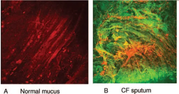
CF is a genetic disease caused by a gene mutation that affects the gene responsible for encoding cystic fibrosis transmembrane conductance regulator (CFTR) protein.181 Due to the caused lack of bicarbonate-chloride exchange, one of the proteins functions, mucin solubility lessens and issues of mucin aggregation occurs.182-184 Images of CF sputum compared to the mucus of a healthy patient are seen in Figure 1.14.
0 500 1000 1500 2000 2500 3000
Healthy Patient Mild COPD Moderate COPD Severe COPD
Patient Healthy Mild COPD Moderate COPD Severe COPD
Figure 1.14 Laser scanning confocal micrograph of normal mucus (A) and sputum of a CF patient (B). Image from a review in CHEST with permission from the author**1
CF is most prevalent in white populations (1 in 3000 births are born with CF in this ethnic group) and is the most lethal genetic disease for this population, with occurrence most prominent in North America and northwest Europe.185 Current life expectancy for a child born with the disease is 37 years of age.186 Common symptoms of CF are listed in Table 1.3.
Table 1.3 Common symptoms of CF at different stages of life
Symptoms of Cystic Fibrosis
General
• Family history of cystic fibrosis
• Salty-tasting skin
• Clubbing of fingers and toes
• Cough with sputum production
• Mucoid Pseudomonas aeruginosa isolated from airway secretions
• Hypochloraemic metabolic alkalosis
Neonatal
• Protracted jaundice
• Abdominal or scrotal calcifications
• Intestinal atresia
Infancy
• Persistent infiltrates on chest radiographs
• Failure to thrive
• Chronic diarrhoea
• Abdominal distention
• Cholestasis
• Staphylococcus aureus pneumonia
• Idiopathic intracranial hypertension (vitamin A deficiency)
• Haemolytic anaemia (vitamin E deficiency)
Childhood
• Chronic pansinusitis or nasal polyposis
• Steatorrhoea
• Rectal prolapse
• Idiopathic recurrent or chronic pancreatitis
• Liver disease
Adulthood
• Allergic bronchopulmonary aspergillosis
• Chronic pansinusitis or nasal polyposis
• Bronchiectasis
• Haemoptysis
• Idiopathic recurrent pancreatitis
• Portal hypertension
1.4.3 Common Approaches Toward Mucolysis
Treatments for CF and COPD have largely been symptom focused and no current
methods have been able to completely overcome the overexpression of mucins in the respiratory tract. However, work has been done towards reducing the size of mucins via mucolysis, thus lowering their viscosity and elasticity so that they may be cleared easier. These methods include the use of non-destructive mucolysis and destructive mucolysis.
1.4.3.a Non-destructive Mucolysis
The impedance on hydration caused by the hydrophobic globular knots along the polymer backbone of mucins has led scientists to find methods of unraveling these knots. To do this, the hydrogen bonding and ionic interactions throughout the mucus gel must be interrupted.
Surfactants have been used as a method for this, including sodium dodecylsulfate187, and dodecyl betainate188. They have shown that reducing the inter-mucin interactions reduce the elastic and viscous moduli and can reduce the magnitude of adhesion of mucus to solid substrates.187 Other ionic and nonionic agents have been tested as well for their ability to aid ciliary clearance. Sodium Chloride189,190 and dextran191 were shown to reduce the crosslink density of mucin networks, assisting MCC.
1.4.3.b Destructive Mucolysis
sputum.194 Dornase alfa does not over-reduce these molecules to a point of liquefying the mucus gel so that it retains its necessary functionalities, and was the first FDA approved mucolytic prescribed in the United States.195,196
N-acetylcysteine (NAC) is another common destructive mucolytic agent. It is a thiol reducing agent that reduces the viscosity of sputum via mucin-chain scission, and though not used heavily in North America, has shown efficacy in aiding the clearance of sputum in COPD and CF patients.197 NAC reduces disulfide bonds within the mucus gel network to free thiols. As more novel disulfide reducing agents have been synthesized by today’s drug makers, NAC was found not to be a very efficient therapeutic mucolytic though early in vitro data was
promising.198-200 The reason for this is unknown and currently being studied by researchers worldwide.
1.4.4 Characterization of Mucins 1.4.4.a RT-PCR
RT-PCR is used to detect gene expression qualitatively by utilizing RNA of interest to create complementary DNA transcripts.201 These transcripts are then amplified using PCR, and can be used to determine the expressed genes within a biological sample.202,203 This has been shown to be highly useful in determining MUC genes in samples166 as well as quantifying the magnitude of overexpression of MUC genes in diseased sputum samples204,205, and identifying viruses in sputum.206,207
1.4.4.b Rheology
Biological scientist can use this methodology to understand the differences between different mucins209, the mucin response under different pH conditions210, 211, and changes in the mucin network after mucolysis methods have been applied.212
1.4.4.c Mass Spectrometry
Mass spectrometry methods have been a great tool to both quantify mucins213 and characterize them down to the peptides which make them up.214 Its use has changed the way scientist can analyze these intricate gels. Utilizing mass spectrometry as a detector after chromatography methods has been quite beneficial for size information and understanding the major MUC genes at different locations of the respiratory tract.215
1.4.4.d. Western Blot
To grasp understanding of the molecular weight of mucins and how their size is affected under various conditions, western blot is performed. Western blotting is the staple procedure in biomedical research for determining the rough molecular weight of a biological molecule. It involves the gel electrophoresis of native proteins which are stained with antibodies, and determining their size based on the resolution of the stained band they create in references to a marker of known size.216, 217 This method is what has given the molecular weight estimates of the identified MUC genes to-date. Western blot testing has shown that MUC5B and MUC5AC are of molecular weights larger than 25 MDa, but because of the nature of the test, cannot provide accurate quantitative data.218, 219
1.4.5 Research Objectives
REFERENCES
1. Stevens, M. P.; Polymer Chemistry an Introduction 1999, 3, 175. 2. Schoff, C. K.; J. Coat. Tech. 1999, 71, 888, 57-72.
3. Kornum, L. O.; Raaschou Nielsen, H. K.; Prog. Org. Coat. 1980, 8, 275-324. 4. Bierwagen, G. F.; Prog. Org. Coat. 1975, 3, 101-113.
5. Fink-Jensen, Farbe Lack 1962, 68, 155-162.
6. Patton, T. C.; J. Paint Technol. 1966, 38, 502, 656-666. 7. Orchard, S. E.; Appl. Sci. Res. A 1962, 11, 451.
8. Smith, N. P. D.; Orchard, S. E.; Rhind-Tutt, A. J.; J. Oil Colour Chem. Assoc. 1961, 44, 618. 9. Overdiep, W. S.; Physiochemical Hydrodynamics, in: D.B. Spalding (Ed.) 1978, 683.
10.Overdiep, W.S.; Prog. Org. Coat. 1986, 14, 159.
11.Hawe, M.; Handbook of Industrial water soluble polymers 2007, 32-72.
12.Bosma, M.; Brinkhuis, R.; Rensen, E.; Watson, R., Prog. Org. Coat. 2011, 26-33. 13.Cramer, S.; Speiss, W.; Macromol. Chem. Phys. 2002, 203, 192-198.
14.Gerlock, J.; Bauer, D.; Polymer Degradation and Stability 1988, 20, 123-134. 15.Sim, S.; Forbes, M. D. E.; J. Phys. Chem. B 2014, 118, 9997-10006.
16. Goldstein, N.; BioCycle 2012 , 53, 1, 4.
17.Ratner, B.; Hoffman, A.; Schoen, F.; Lemons, J.; Biomaterials Science 2012, 3, 179-181. 18. Martina, M.; Hutmacher, D. W.; Polym. Int. 2007, 56, 145.
19.Xie, J.; Lee, S.; Chen, X.; Adv. Drug Del. Rev. 2010, 62, 11, 1064-1079. 20.15. Vert, M.; Biomacromolecules 2005, 6, 538,16.
23.Xuan, S.; Lee, C.U.; Chen, C.; Doyle, A.B.; Zhang, Y.; Guo, L.; John, V.T.; Hayes, D.; Zhang, D.; Chem Mater 2016, 28, 3, 727-737.
24.Aseyev, V.; Tenhu, H.; Winnik, F. M.; Self Organized Nanostructures of Amphiphilic Block Copolymers II 2011, 29–89.
25.Bae, Y. C.; Lambert, S. M.; Soane, D. S.; Prausnitz, D. S.; Macromolecules 1991, 24, 4403– 4407.
26.Halperin, A.; Kröger, M.; Winnik, F. M.; Angew. Chem., Int. Ed. 2015, 54, 15342–15367. 27.Seuring, J.; Agarwal, S.; Macromol. Rapid Commun. 2012, 33, 1898–1920.
28.Zhang, Q.; Hoogenboom, R.; Prog. Polym. Sci. 2015, 48, 122–142.
29.Plamper, F. A.; Schmalz, A.; Müller, A. H. E.; J. Am. Chem. Soc. 2007, 129, 14538–14539. 30.Plamper, F. A.; Steinschulte, A. A.; Hofmann, C. H.; Drude, N.; Mergel, O.; Herbert, C.;
Erberich, M.; Schulte, B.; Winter, R.; Richtering, W.; Macromolecules 2012, 8021–8026. 31.Niskanen, J.; Wu, C.; Ostrowski, M.; Fuller, G. G.; Hietala, S.; Tenhu, H.; Macromolecules
2013, 46, 2331–2340.
32.Maeda, Y.; Ide, M.; Kitano, H.; J. Mol. Liq. 1999, 80, 149– 163. 33.Kitano, H.; Polym. J. 2016, 48, 15–24.
34.Seuring, J.; Agarwal, S.; Macromol. Chem. Phys. 2010, 211, 2109–2117. 35.Xu, H.; Meng, F.; Zhong, Z.; J. Mater. Chem. 2009,19, 4183-4190.
36.Bang, E.-K.; Lista, M.; Sforazzini, G.; Sakai, N.; Matile, S.; Chem. Sci. 2012, 3, 1752. 37.Ko, N. R.; Yao, K.; Tang, C.; Oh, J. K.; J. Polym. Sci. A Polym. Chem. 2013, 51, 3071-3080. 38.Bauhuber, S.; Hozsa, C.; Breunig, M.; Göpferich, A.; Advanced Materials 2009, 21, 3286. 39.Emilitri, E.; Ranucci, E.; Ferruti, P.; J. Polym. Sci. A Polym. Chem. 2005, 43, 1404. 40.Meng, F.; Hennink, W. E.; Zhong, Z.; Biomaterials 2009, 30, 2180.
41.Pan, Y. J.; Chen, Y. Y.; Wang, D. R.; Wei, C.; Guo, J.; Lu, D. R.; Chu, C. C.; Wang, C. C.; Biomaterials 2012, 33, 6570.
43.Hu, J. H.; Yu, H.; Gan, L. H.; Hu, X.; Soft Matter 2011, 7, 11345–11350. 44.Lin, S. L.; Wang, Y. Y.; Cai, C. H.; Xing, Y. H.; Lin, J. P.; Chem, T.; He, X. H.;
Nanotechnology 2013, 24, 085602.
45.Jin, Q. A.; Liu, G. Y.; Liu, X. S.; Ji, J. A.; Soft Matter 2010, 6, 5589–5595.
46.Shen, G. Y.; Xue, G. S.; Cai, J.; Zou, G.; Li, Y. M.; Zhang, Q. J.; Soft Matter 2013, 9, 2512– 2517.
47.Hu, D.; Li, Y. F.; Niu, Y. L.; Li, L.; He, J. W.; Liu, X. Y.; Xia, X. N.; Lu, Y. B.; Xiong, Y. Q.; Xu, W. J.; RSC Adv. 2014, 4, 47929–47936.
48.Wei, R. B.; Ma, J. Y.; Zhang, H. X.; He, Y. N.; J. Appl. Polym. Sci. 2016, 133, 43695. 49.Wei, R. B.; Wang, X. G.; He, Y. N.; Chin. Chem. Lett. 2015, 26, 857–861.
50.Huang, G. X.; Zhu, J.; Zhang, Z. B.; Zhang, W.; Zhou, N. C.; Zhu, X. L.; J. Macromol. Sci., Part A: Pure Appl. Chem. 2013, 50, 193–199.
51.Hu, J.; Wang, X.; Zheng, S. H.; Polym. Adv. Technol. 2012, 23, 1590–1595.
52.Blasco, E.; Schmidt, B. V. K. J.; Barner-Kowollik, C.; Pinol, M.; Oriol, L.; Polym. Chem. 2013, 4, 4506–4514.
53.Guo, W. J.; Wang, T. S.; Tang, X. D.; Zhang, Q.; Yu, F. Q.; Pei, M. S.; J. Polym. Sci., Part A: Polym. Chem. 2014, 52, 2131–2138.
54.Chen, C. J.; Liu, G. Y.; Liu, X. S.; Li, D. D.; Ji, J.; New J. Chem. 2012, 36, 694–701.
55.Dong, R. J.; Liu, Y.; Zhou, Y. F.; Yan, D. Y.; Zhu, X. Y.; Polym. Chem. 2011, 2, 2771–2774. 56.Dong, S. Y.; Gao, L. Y.; Li, J. Y.; Xu, D. H.; Zhou, Q. Z.; Polym. Chem. 2013, 4, 3968–
3973.
57.Liu, L. C.; Rui, L. L.; Gao, Y.; Zhang, W. A.; Polym. Chem. 2014, 5, 5453–5460. 58.Yang, J.; Li, Z. T.; Zhou, Y. J.; Yu, G. C.; Polym. Chem. 2014, 5, 6645–6650. 59.Zhou, X. R.; Du, Y.; Wang, X. G.; ACS Macro Lett. 2016, 5, 234–237.
60.Marturano, V.; Cerruti, P.; Carfagna, C.; Giamberini, M.; Tylkowski, B.; Ambrogi, V.; Polymer 2015, 70, 222–230.
62.Yang, Y. Z.; Tang, Q.; Gong, C. B.; Ma, X. B.; Peng, J. D.; Lam, M. H. W.; New J. Chem. 2014, 38, 1780–1788.
63.Gong, C. B.; Yang, Y. Z.; Gao, C.; Tang, Q.; Chow, C. F.; Peng, J. D.; Lam, M. H. W.; J. Sol-Gel Sci. Technol. 2013, 67, 442–450.
64.Romasanta, L. J.; Lopez-Manchado, L. J.; Verdejo, R.; Prog. Polym. Sci. 2015, 51, 188–211. 65.Liu, H. L.; Zhang, L. Q.; Yang, D.; Ning, N. Y.; Yu, Y. C.; Yao, L.; Yan, B. Y.; Tian, M.; J.
Phys. D: Appl. Phys. 2012, 45, 485303.
66.Bhandari, B.; Lee, G. Y.; Ahn, S. H.; Int. J. Precis. Eng. Manuf. 2012, 13, 141–163. 67.Song, J.; Jeon, J. H.; Oh, I. K.; Park, K. C.; Macromol. Rapid Commun. 2011, 32, 1583–
1587.
68.He, Q. S.; Yu, M.; Song, L. L.; Ding, H. T.; Zhang, X. Q.; Dai, Z. D.; J. Bionic. Eng. 2011, 8, 77–85.
69.Gugliuzza, A.; Drioli, E.; J. Membr. Sci. 2013, 446, 350– 375.
70.Bhattacharya, S.; Bepari, B.; Bhaumik, S.; Mech. Based Des. Struct. Mach. 2014, 42, 312– 325.
71.Lu, J.; Kim, S. G.; Lee, S.; Oh, I. K.; Macromol. Chem. Phys. 2011, 212, 635–642. 72.Engel, L.; Kruk, S.; Shklovsky, J.; Shacham-Diamand, Y.; Krylov, S.; J. Micromech.
Microeng. 2014, 24, 125027.
73.Kim, S. S.; Kee, C. D.; Int. J. Precis. Eng. Manuf. 2014, 15, 315–321.
74.Jeon, J. H.; Oh, I. K.; Kee, C. D.; Kim, S. J.; Sens. Actuators, B 2010, 146, 307–313. 75.Kunchornsup, W.; Sirivat, A.; Sens. Actuators, A 2014, 220, 249–261.
76.Wang, X. L.; Oh, I. K.; Cheng, T. H.; Polym. Int. 2010, 59, 305–312. 77.Wang, X. L.; Oh, I. K.; Xu, L.; Sens. Actuators, B 2010, 145, 635–642.
78.Migliorini, L.; Santaniello, T.; Yan, Y. S.; Lenardi, C.; Milani, P.; Sens. Actuators, B 2016, 228, 758–766.
80.Morales, D.; Palleau, E.; Dickey, M. D.; Velev, O. D.; Soft Matter 2014, 10, 1337–1348. 81.Indermun, S.; Choonara, Y. E.; Kumar, P.; du Toit, L. C.; Modi, G.; Luttge, R.; Pillay, V.;
Int. J. Pharm. 2014, 462, 52–65.
82.Kwon, G. H.; Choi, Y. Y.; Park, J. Y.; Woo, D. H.; Lee, K. B.; Kim, J. H.; Lee, S. H.; Lab Chip 2010, 10, 1604–1610.
83.Jackson, N.; Cordero, N.; Stam, F.; J. Polym. Sci., Part B: Polym. Phys. 2013, 51, 1523– 1528.
84.Jackson, N.; Stam, F.; J. Appl. Polym. Sci. 2015, 132, 41687.
85.Bassil, M.; Ibrahim, M.; El Tahchi, M.; Soft Matter 2011, 7, 4833–4838.
86.Glazer, P. J.; van Erp, M.; Embrechts, A.; Lemay, S. G.; Mendes, E.; Soft Matter 2012, 8, 4421–4426.
87.Jo, C.; Naguib, H. E.; Kwon, R. H.; Smart Mater. Struct. 2011, 20, 045006.
88.Yang, C.; Wang, W.; Yao, C.; Xie, R.; Ju, X. J.; Liu, Z.; Chu, L. Y.; Sci. Rep. 2015, 5, 13622.
89.Borisova, O. V.; Billon, L.; Richter, R. P.; Reimhult, E.; Borisov, O. V.; Langmuir 2015, 31, 7684–7694.
90.Cao, Q. Q.; Zuo, C. C.; Li, L. J.; Yan, G.; Biomicrofluidics 2011, 5, 044119.
91.Wood, K. C.; Zacharia, N. S.; Schmidt, D. J.; Wrightman, S. N.; Andaya, B. J.; Hammond, P. T.; Proc. Natl. Acad. Sci. U. S. A. 2008, 105, 2280–2285.
92.Al-Badri, Z. M.; Maddikeri, R. R.; Zha, Y. P.; Thaker, H. D.; Dobriyal, P.; Shunmugam, R.; Russell, T. P.; Tew, G. N.; Nat. Commun. 2011, 2, 482.
93.Zha, Y. P.; Maddikeri, R. R.; Gido, S. P.; Tew, G. N.; J. Inorg. Organomet. Polym. Mater. 2013, 23, 89–94.
94.Zha, Y. P.; Thaker, H. D.; Maddikeri, R. R.; Gido, S. P.; Tuominen, M. T.; Tew, G. N.; J. Am. Chem. Soc. 2012, 134, 14534–14541.
95.Mukherjee, S.; Dinda, H.; Shashank, L.; Chakraborty, I.; Bhattacharyya, R.; Das Sarma, J.; Shunmugam, R.; Macromolecules 2015, 48, 6791–6800.
97.Jiang, B. Y.; Hom, W. L.; Chen, X. Y.; Yu, P. Q.; Payelka, L. C.; Kisslinger, K.; Parise, J. B.; Bhatia, S. R.; Grubbs, R. B.; J. Am. Chem. Soc. 2016, 138, 4616–4625.
98.Miao, W. G.; Qin, L.; Yang, D.; Jin, X.; Liu, M. H.; Chem. – Eur. J. 2015, 21, 1064–1072. 99.Yu, X. D.; Liu, Q. A.; Wu, J. C.; Zhang, M. M.; Cao, X. H.; Zhang, S.; Wang, Q.; Chen, L.
M.; Yi, T.; Chem. – Eur. J. 2010, 16, 9099–9106.
100. Fan, J. W.; Zou, J.; He, X.; Zhang, F. W.; Zhang, S. Y.; Raymond, J. E.; Wooley, K. L.; Chem. Sci. 2014, 5, 141– 150.
101.Min, Y. Q.; Huang, S. Y.; Wang, Y. X.; Zhang, Z. J.; Du, B. Y.; Zhang, X. H.; Fan, Z. Q.; Macromolecules 2015, 48, 316– 322.
102.Schaefer, M.; Icli, B.; Weder, C.; Lattuada, M.; Kilbinger, A. F. M.; Simon, Y. C.; Macromolecules 2016, 49, 1630–1636.
103.Sommer, M.; Komber, H.; Macromol. Rapid Commun. 2013, 34, 57–62. 104.Chen, W. Q.; Du, J. Z.; Sci. Rep. 2013, 3, 2162.
105.Gao, Z. G.; Fain, H. D.; Rapoport, N.; J. Controlled Release 2005, 102, 203–222. 106.Husseini, G. A.; Myrup, G. D.; Pitt, W. G.; Christensen, D. A.; Rapoport, N. Y.; J.
Controlled Release 2000, 69, 43– 52.
107.Marin, A.; Sun, H.; Husseini, G. A.; Pitt, W. G.; Christensen, D. A.; Rapoport, N. Y.; J. Controlled Release 2002, 84, 39–47.
108.Rapoport, N. Y.; Int. J. Pharm. 2004, 277, 155–162.
109.Rapoport, N. Y.; Christensen, D. A.; Fain, H. D.; Barrows, L.; Gao, Z.; Ultrasonics 2004, 42, 943–950.
110.Rapoport, N. Y.; Kennedy, A. M.; Shea, J. E.; Scaife, C. L.; Nam, K. H.; J. Controlled Release 2009, 138, 268– 276.
111.Zhang, H. J.; Xia, H. S.; Wang, J.; Li, Y. W.; J. Controlled Release 2009, 139, 31–39. 112.Narayan, R. In Science and Engineering of Composting: Design, Environmental,
Microbiological and Utilization Aspects 1993, 339.