150 |
P a g e
IMPLEMENTATION OF MIMO OFDM
TRANSCRECEIVER FOR INCREASING DATA RATES
Madhuri H Jadhav
1, Prof .Inamdar M U
2 1,2Dept. of Electronics & telecommunication,
Siddhant College Of Engineering, Sudumbare, Pune, India
ABSTRACT
Now a days the need for wireless data transmission is being widely used for communication purpose. Orthogonal frequency division multiplexing (OFDM) which is multi carrier communication technique can be used for wireless mobile communication as it has the property to overcome channel fading. While multiple inputs multiple outputs (MIMO) is the technique of implementing multiple antennas at the transmitter as well as receiver side to increase the data rates.In this paper, by taking the advantage of OFDM & MIMO a system has been implemented to get the data rates up to several hundred mbps.The first stage will be verification of each block using matlab. After the algorithm is verified, the hardware implementation will be obtained by constructing block diagram in Simulink. Then a VHDL code will be imported into Simulink via Xilinx system generator block set which will create bit true and cycle accurate hardware model. The resultant hardware model will be programmed into FPGA prototyping board.
Index terms
— MIMO, OFDMI.
I
NTRODUCTIONThe need for high speed data transmission is increasing now a day. The mobile communication industry faces the problem of providing services like voice communication and wireless multimedia whose data rate ranges from few kbps to mbps. Many systems have been proposed in recent years using OFDM. OFDM has been recognized as an outstanding method for high-speed cellular data communication where its implementation relies on very high-speed digital signal processing.OFDM system can be implemented using various techniques like ASIC, one of the fastest method. But have the disadvantage of inflexibility and longer time to market. Another method is by using microprocessor, but it requires larger peripherals. One of the best technique is by using FPGA.
By combining MIMO and OFDM the data rates can be further increased up to few hundred mbps [6].In MIMO multiple antennas are used at transmitter and receiver side. MIMO can be used to overcome the channel fading problem as well as to increase the gain.By taking the advantage of MIMO and OFDM, a transreceiver can be implemented using FPGA. Simulation results are obtained using MATLAB.In this paper hardware implementation of MIMO OFDM using FPGA considering IEEE 802.11n standard has been proposed.
II.
BRIEF
REVIEW
151 |
P a g e
In 2006, Yin, Hujun of Intel Corporation reviewed the design philosophies for uplink and downlink of OFDMA systems and demonstrates that OFDMA is a superior access technology for broadband wireless data network in his paper in IEEE Sarnoff Symposium [13].
In 2007, Yu-Wei Lin and Chen-Yi Lee published a paper [3] ”Design of an FFT/IFFT Processor for MIMO OFDM Systems" In 2007,Ming Jiang and LajosHanzo,published paper on “Multiuser MIMO-OFDM for Next-GenerationWireless Systems” using this system multiusers can use the system.
Also there are various other international research papers all establishing MIMO-OFDM systems as the better technology.
2.1 ORTHOGONAL FREQUENCY DIVISION MULTIPLEXING (OFDM)
OFDM is a combination of modulation and multiplexing technique, in which the bandwidth is shared among each modulated data sources [1].OFDM is a multicarrier modulation technique, which uses several carriers, within the bandwidth, to convey the information from source to destination. Each carrier may use one of the several available digital modulation techniques like BPSK, QPSK, and QAM.
The transmitter stage of an OFDM transceiver takes data, converts, and encodes it into a serial stream before modulation. The OFDM signal is generated using an Inverse Fast Fourier Transform (IFFT). The receiver stage of the transceiver simply reverses the process.
2.2 MULTIPLE INPUT MULTIPLE OUTPUT (MIMO)
In MIMO, the system employs the fact that the received signal from one transmit antenna can be different than the received signal from a second antenna. This is most common in indoor or dense metropolitan areas where there are many reflections and multipath between transmitter and receiver [8]. In this case, a different signal can be transmitted from each antenna at the same frequency and is recovered at the receiver.
Fig.1 Transmit 2 Receive (2x2) MIMO channel
III. METHODOLOGY FOR DESIGN& IMPLEMENTATION
152 |
P a g e
imported into Simulink via Xilinx system generator block set which will create hardware model.The resultant hardware model will be programmed into FPGA prototyping board
IV. PROPOSED MIMO OFDM TRANSRECEIVER BLOCKS DIAGRAM.
The overall system is split into two main parts: the transmitter and the receiver. The transmitter section consists of multiple inputs fed to the transmitter block using MIMO technique.
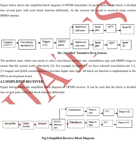
4.1 SIMPLIFIED TRANSMITTER
Figure below shows the simplified block diagram of OFDM transmitter. It can be seen that the block is divided into several parts with each block function differently. At the receiver the signal is received using various
MIMO antenna
The problem starts where one needs to select convolution encoder rate, constellation type and MIMO usage to ensure that the system works effectively [2]. For example in figure 5.2 we have selected convolution rate 1/2, 2/3 mapper and QAM constellation as it provides higher data rates. All block set function is implemented in the FPGA development board.
4.2 SIMPLIFIED RECEIVER
Figure below shows the simplified block diagram of OFDM receiver. It can be seen that the block is divided into several parts with each block function differently.
153 |
P a g e
At the receiver the blocks operation depends on the method used to code the signal in transmitter. That is at the transmitter we have selected convolution rate 1/2, 2/3 mapper and QAM constellation so the reverse will be done at receiver using same selected rates and constellation.
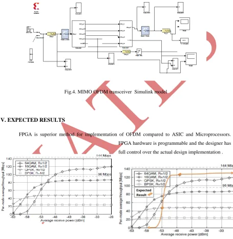
Above transmitter and receiver block diagram is implemented in MATLAB using Simulink and xilin system generator. Combined model of transmitter and receiver is called as MIMO OFDM transreciver which is shown below.
Fig.4. MIMO OFDM transceiver Simulink model
V. EXPECTED RESULTS
FPGA is superior method for implementation of OFDM compared to ASIC and Microprocessors. FPGA hardware is programmable and the designer has
full control over the actual design implementation .
Fig 5.Actual Constellation Performance Fig 6. Expected Constellation Performance
154 |
P a g e
Our main aim is to implement a MIMO OFDM baseband transceiver on an FPGA by proper selection of one of the sixteen configurations to fulfill the need for high-speed data transmission for a wireless communication system with reasonable prices of hardware implementation
In figure 5.1 we have different data rates which are achieved till date by using different constellation types, and figure 5.2 shows the expected results to be obtained in future in order to achieve high speed data transmission.
VI. CONCLUSION
OFDM systems are the solution to our ever increasing data rate needs. By implementing a MIMO OFDM baseband transceiver by proper selection of one of the sixteen configurations we expect the need for high-speed data transmission for a wireless communication.
REFERENCES
[1] http://gaussianwaves.blogspot.com/2011/07/simulation-of-ofdm-system-in-matlab-ber.html
[2] ZohaPajoudi, SiedHamidreza, “Hardware Implementation of an 802.11n MIMO OFDM Transceiver,” in IEEE Jour. 978-1-4244-2750-5. (2008)
[3] Yu Wei Lin, Chen Yi Lin, “Design of FFT/IFFT Processor for MIMO OFDM Systems,” IEEE Transaction on circuit and system, Vo1.54, no. 4 pp. 807-815, 2007.
[4] Ashok Jhunjhunwala, “Next Generation wireless for rural areas,” in Indian Journal of Radio and Space Physics, Vol.36. pp 165-167, 2007.
[5] K. C. Chang, G E Sobelman, “FPGA Based Design of a Pulsed-OFDM system," in IEEE Jour. 1-4244-0387-1/2006.
[6] Z. Y. Ding, C Y Chen, T D Chiueh, "Design of a MIMO-OFDM baseband receiver for next generation wireless LAN ," in Proc. of ISCAS 06, vol. 1 , pp. 5650-5654, Island of Kos, Greece, 2006.
[7] K.C.Chang G.E. Sobelman, E Saberinia, and A.H. Tewfik, “Transmitter architecture for pulsed OFDM,” IEEE APCCAS, 6-9 Dec. 2004, pp 693-696
[8] K. F. Lee, D B William, "A space-frequency transmitter diversity technique for OFDM systems," in Proc. Globecom 03, San Francisco, USA, vol.3, pp.24-28, 2003.
[9] D. Getsberg, Shafi, M.,Da-shanShiu,Smith, P.J., " From theory to practice: An overview of MIMO space-time coded wireless systems," in IEEE Jour. Sel. Areas in Commun.,vo1.21, no. 38 pp. 281-301, 2003.
[10] V. Tarokh, H Jafarkhani, A R Calderbank, "Space-time block coding for wireless communications: performance results," in IEEE Jour. On Sel. Areas in Commun.,vol 17, no. 3.pp. 451-460, 1999.
[11] S. M. Alamouti, “A simple transmit diversity scheme for wireless communications," in IEEE Jour. Sel. Areas in Commun., vo1.16, no. 8 pp. 1451-1458, 1998.
[12] Ramjee Prasad “OFDM for wireless communication system” Artech House, Inc. Boston, London.