t o M u ltic a s t C o m m u n ic a tio n
in a D a ta g r a m I n te r n e tw o r k
A n th o n y J. B allard ie
May, 1995
De p a r t m e n t o f Co m p u t e r Sc i e n c e Un i v e r s i t y Co l l e g e Lo n d o n
Un i v e r s i t y o f Lo n d o n
A thesis subm itted to the University of London for the degree of
All rights reserved
INFORMATION TO ALL USERS
The quality of this reproduction is dependent upon the quality of the copy submitted.
In the unlikely event that the author did not send a complete manuscript and there are missing pages, these will be noted. Also, if material had to be removed,
a note will indicate the deletion.
uest.
ProQuest 10017691
Published by ProQuest LLC(2016). Copyright of the Dissertation is held by the Author.
All rights reserved.
This work is protected against unauthorized copying under Title 17, United States Code. Microform Edition © ProQuest LLC.
ProQuest LLC
789 East Eisenhower Parkway P.O. Box 1346
M ulticasting is a technique that enables a single packet transm ission to reach one or more destinations or group.
The primary benefits o f a packet reaching m ultiple destinations from a single transm ission are threefold: bandwidth minimization', the exploitation o f parallelism in the network', the optim ization o f tra n sm itter costs.
In this thesis we investigate and analyse each of the different network layer m ulticast algorithms and protocols, looking in particular at their scalability, since m ulticast scalability was the primary m otivator for this work.
Our first and m ost significant contribution involves the presentation o f a new m ulticast archi tecture and protocol, designed for best-effort, connectionless datagram networks such as the IP Internet. This new architecture typically offers considerably more favourable scaling characteristics than do existing m ulticast schemes.
Our other m ost significant contribution is the security architecture that is integral in our new m ulticast proposal. It provides authentication o f routers that make up a m ulticast delivery tree, and end-system subscribers. It also doubles in providing a solution to the well-known m ulticast key distribution problem.
We also provide an analysis of the security threats to m ulticast com m unication, and propose various m ethods to counter those threats.
One other contribution is presented: a proposal for A T M multicasting. This proposal is not a contribution of the author, but is based heavily on the author’s m ulticast architecture and protocol. We therefore consider it appropriate to include an overview of this work here. As part of our discussion on ATM m ulticast, we also provide an explanation o f why traditional IP m ulticast schemes are not suited to the ATM paradigm. We proceed to show how our new m ulticast architecture com plem ents the ATM model.
T he quintessential question this thesis poses is: how can m ulticast be best achieved? Our conclusion is that there is no best way, but there are trade-offs to consider for each o f the different m ethods, and each m ethod has its place in the range of m ulticast solutions, just as each of the
unicast routing protocols has its place in the Internet^.
In writing this page I can a t last say I have come to the end of a long road I set out on, not ju st 3 years ago when I started this PhD, but many years before th a t. B ut th a t’s a long story.
During the past 3 years I have been privileged to work closely with some of the best and most reputable people in the field of networking. They always set the highest standards to which I had to become accustomed, and for which I am extremely grateful.
Most especially, I would like to thank Jon Crowcroft, my supervisor, and Paul Francis, currently a t N TT Japan. Jon not only provided me with direction and focus, b ut also gave me the opportunity to be his student. In retrospect, I would not have chosen any other. Paul also played a m ajor role in this PhD. W ithout the many brainstorm ing sessions we had early on, this work would not have come about - the idea of m ulticasting using a shared tree was his. I think I have partly repaid him in th a t he is now a b etter tennis player, but this is a debt th a t will be long outstanding.
Paul and Jon also secured funding for the duration of my PhD from Bell Communica tions Research (Bellcore), U.S.A. I would like to thank Bellcore, not only for their financial support, which made student life a bit easier, but also for allowing me to visit and become p art of their networking team on several occasions. Special thanks to Ramesh Govindan who assisted, and provided many insights, in my initial CBT im plem entation, and Liang Wu and Bruce Davie for all their work behind the scenes which made my visits possible.
Steve Deering (Xerox PARC) should not go w ithout mention here. W ithout him realising it, his knowledge and expertise have, in part, motivated me during my PhD. This work has also benehtted from his insights and constructive criticism as it has progressed through the IDMR working group of the IETF.
My time at UCL wouldn’t have been half as enjoyable if not for my PhD student friends and colleagues here. Thanks for all the good times in the pub and the Nepalese restaurant. I hope we continue the tradition long hereafter.
Special thanks too to Alex Coddington for proof-reading all of this - it makes a lot more sense now!
And I m ustn’t forget to mention my dear friends, Sarah and Dave. I can ’t thank you enough for letting me share your home, for all the good laughs, and much more.
A u t h o r ’s N o t e s
• S ta te m en t o f W ork.
In light of numerous co-authored publications related to the work presented in this thesis it is maybe necessary to make clear the work attrib u ted by the author. All of the work presented in this thesis is the sole contribution of the author, Tony Ballardie.
Jon Crowcroft and Paul Francis appear either together or separately as secondary co-authors on some of the related publications. Paul Francis appeared on some of the early documents since the idea of using a shared tree for multicasting was his. He also provided valuable review feedback with regards to those works, and therefore it was considered appropriate th a t he should appear as a secondary co-author.
Jon Crowcroft appears on most publications due to UCL CS departm ental policy th a t a student must include the supervisor on all conference and journal publications. The term “we” , used throughout, is simply a writing convention.
• G lossary
A glossary of im portant and commonly-used term s is provided near the back of this thesis due to the large number of acronyms used in the field of networking. However, for most of the acronyms used we provide its definition the first time it appears.
• R eferen ce List
The reference list provided a t the end of this thesis makes numerous references to “work in progress” . These are Internet-drafts - working docum ents of the Internet Engineering Task Force (IETF), its Areas, and its Working Groups. These docu m ents are valid for a maximum of six months, after or during which they must be updated, replaced, or obsoleted. It is not perm itted to cite an Internet-draft other than as a “working draft” or “work in progress” .
If you wish to retrieve any such docum ent listed in th e reference list, it is recom mended you send e-mail to:
internet-drafts@cnri. reston. va. us
1 In tro d u ctio n 1
1.1 B a c k g ro u n d ... 2
1.2 Thesis Overview ... 5
2 R ela ted W ork 8 2.1 Wall’s Work on Centre Based F o r w a r d in g ... 9
2.2 The Construction of W all’s “Centre-Trees” ... 13
2.2.1 A daptation for S elective-B roadcast... 14
2.3 Deering’s W o r k ... 15
2.3.1 The Distance-Vector M ulticast A lg o r ith m ... 16
2.3.2 The Link-State M ulticast A lg o r ith m ... 18
2.4 Protocol Independent M ulticast ( P I M ) ... 19
3 T h e C ore B a sed T ree (C B T ) M u ltica st A rc h ite c tu r e 22 3.1 In tro d u c tio n ...22
3.3 Existing M ulticast A rc h ite c tu re ...24
3.3.1 Some Shortcomings of the Existing A r c h ite c tu r e ...24
3.4 CBT - The New A r c h ite c tu r e ... 25
3.4.1 A rchitectural Overview ...25
3.4.2 A rchitectural J u s tific a tio n ...29
3.4.3 The Implications of Shared T r e e s ... 30
3.4.4 Simulation R e s u l t s ...31
3.4.5 Core Placement and M anagem ent ... 33
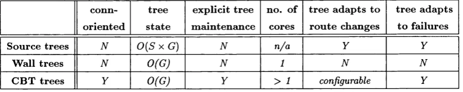
3.5 How Wall’s Trees Differ from CBT T re e s ... 34
3.5.1 CBT and “Anycasting” ... 35
3.6 C hapter S u m m a r y ...38
4 M u ltic a st S ca la b ility 40 4.1 In tro d u c tio n ...40
4.2 The Scalability of the Distance-Vector M ulticast A lg o r it h m ... 42
4.2.1 Group S tate Information ...42
4.2.2 Bandwidth Consumption ...44
4.2.3 Processing C o s t s ... 45
4.3 The Scalability of the Link-State M ulticast A lg o r it h m ... 45
4.3.1 C roup S tate Information ...46
4.3.3 Processing C o s t s ...47
4.4 The Scalability of the PIM A r c h ite c tu r e ... 48
4.4.1 Group S tate Information ... 48
4.4.2 Bandwidth Consumption ...50
4.4.3 Processing C o s t s ... 51
4.5 The Scalability of the CBT A rc h ite c tu re ... 52
4.5.1 Group S tate Information ... 52
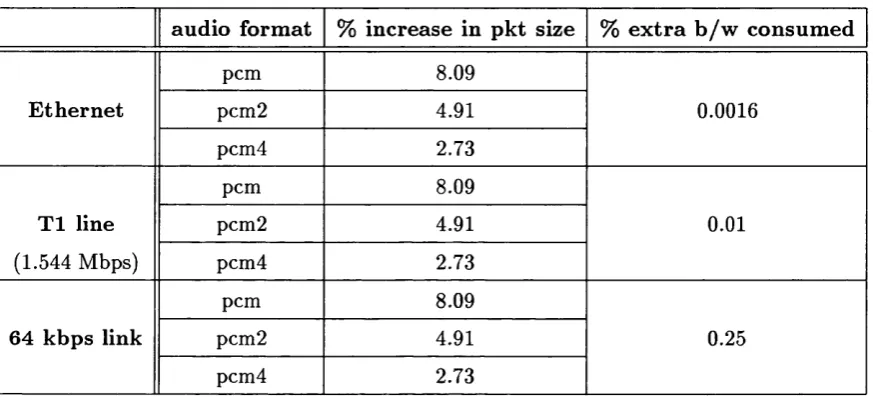
4.5.2 Bandwidth Consumption ...53
4.5.3 Processing C o s t s ... 55
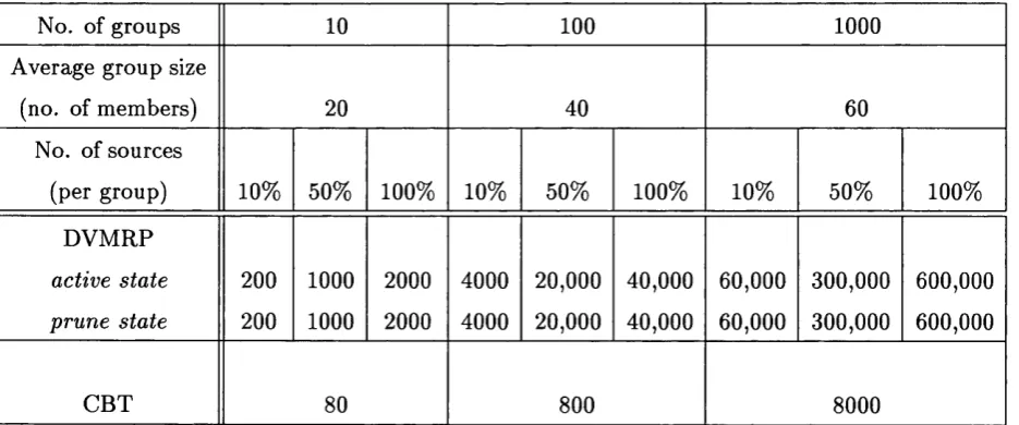
4.6 CBT vs. DVM RP - A Quantitive Analysis ... 56
4.7 C hapter S u m m a r y ...58
5 C B T — T h e P r o to c o l 59 5.1 In tro d u c tio n ...59
5.2 Protocol O v e r v ie w ...60
5.2.1 CBT Group I n i t i a t i o n ... 60
5.2.2 Tree Joining P r o c e s s ... 60
5.2.3 Tree Leaving P ro c e s s ...63
5.2.4 Tree M aintenance I s s u e s ... 63
5.2.5 Core P la c e m e n t... 67
5.2.7 Non-Member S e n d i n g ... 69
5.2.8 D ata Packet Forwarding ... 71
5.2.9 Lower Group Leave L a te n c y ... 76
5.3 CBT Packet Form ats and Message T y p e s ... 78
5.3.1 CBT Header F o r m a t ... 78
5.3.2 Control Packet Header F o r m a t ...79
5.3.3 Prim ary M aintenance Message Types ... 81
5.3.4 Auxiliary M aintenance Message T y p e s ...82
5.4 Interoperability I s s u e s ... 83
5.4.1 Isolation of CBT R o u te s ... 83
5.4.2 Tree Overlap of CBT with O ther S c h e m e s... 84
5.4.3 IC M P in the Presence of Multiple P ro to c o ls ... 85
5.5 Resource R eserv atio n ...87
5.5.1 The Internet Stream Protocol - version 2 (ST-H): O v erv iew ...87
5.5.2 The Resource Reservation Protocol (RSVP): O v erv iew ...88
5.5.3 The Pros and Cons of ST-H vs. R S V P ... 88
5.5.4 Resource Reservation: How CBT Fits I n ...91
5.6 C hapter S u m m a r y ... 93
6.2 Overview ...96
6.3 In tro d u c tio n ... 96
6.4 W hy M ulticast Accentuates Security R is k s ...97
6.5 Specific Types of T h r e a t ...100
6.6 Security F r a m e w o r k ... 101
6.7 Approaches to M ulticast S e c u rity ...102
6.7.1 O v e r v ie w ... 102
6.7.2 A uthorization Infrastructure ...103
6.7.3 Cost-Reducing M e c h a n ism s ... 103
6.8 M otivation for Proposed Key M anagem ent A r c h ite c tu r e ... 105
6.9 M ulticast Group Access Control ...107
6.9.1 O v e r v ie w ...107
6.9.2 Group Access Control - D e ta ils ...109
6.9.3 Secure I C M P ... 110
6.9.4 A uthorization Stam p Creation - Message C o n te n ts ...112
6.10 Multi-Access LANs ... 114
6.11 M ulticast Transit Traffic C o n t r o l ...115
6.11.1 O v e r v ie w ...115
6.11.2 M ulticast Transit Traffic Control - D e ta ils ... 117
6.12 M ulticast Certificate Modification ... 119
6.13 Security A n a ly s is ... 120
6.13.1 Minimizing Assumed Trust ... 120
6.13.2 Security Analysis of Group Access Control ... 121
6.13.3 Security Analysis of M ulticast Transit Traffic C o n t r o l ...121
6.13.4 Security Analysis of Specific T h r e a t s ... 122
6.14 C hapter S u m m a r y ...123
7 C B T S ecu rity A rch itec tu re 125 7.1 In tro d u c tio n ...125
7.2 The Need for Network Layer Security ... 126
7.3 How the CBT A rchitecture Complements S e c u r i t y ...127
7.4 The M ulticast Key D istribution P ro b le m ... 128
7.5 The CBT M ulticast Key D istribution M o d e l... 130
7.5.1 O perational O v e r v ie w ... 131
7.5.2 Example - Integrated Join Verification and M ulticast Key D istribution 132 7.6 A Question of T r u s t ... 137
7.7 C hapter S u m m a r y ...138
8 A T M and M u ltica st 139 8.1 In tro d u c tio n ...139
8.2.1 W hy Source-Based ATM M ulticast Trees are B a d ... 142
8.3 CBT for ATM M u ltic a s t... 143
8.3.1 ACBT E x a m p le s ... 145
8.4 C hapter S u m m a r y ... 152
9 C o n c lu sio n s 153 9.1 Ongoing and Future W o r k ... 154
9.2 Summary of Main C o n tr ib u tio n s ... 155
G lo s s a ry 159
2.1 Delay vs. C o s t ... 10
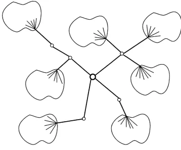
3.1 A CBT m ulticast delivery tree ... 26
3.2 A M ulti-Core CBT t r e e ... 27
3.3 Mesh of m ulticast delivery t r e e s ... 28
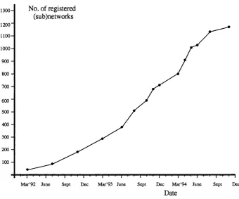
4.1 The Growth of the MBONE between March 1992 and November 1994 . . . 41
4.2 How PIM is used for Inter-Domain M u lticastin g ... 50
5.1 The CBT User Group M anagement I n t e r f a c e ... 61
5.2 A CBT FIB entry in the au th o r’s im plem en tation... 73
5.3 CBT D ata Packet Forwarding on a LAN (originating case) ... 75
5.4 CBT D ata Packet Forwarding on a LAN (receiving c a s e ) ... 76
5.5 CBT Header ...78
5.6 CBT Control Packet H e a d e r...80
5.7 Overlapping delivery t r e e s ...85
5.8 Reservation Loops in a Redundant Topology ... 92
5.9 Network Layer Protocol R e la tio n s h ip s ... 93
6.1 Secure IGM P - Model of In te ra c tio n s...112
6.2 M ulticast Transit Traffic Control - Model of In tera ctio n s...118
6.3 Security-relevant information contain within a p a c k e t... 119
7.1 CBT A uthenticated Join process (hosts and routers) and Key D istribution . 134 8.1 Example ATM Network C o n fig u ra tio n ... 146
8.2 Host Joining CBT Croup in ATM N e t w o r k ...147
8.3 Host Sending to CBT C roup in ATM N e t w o r k ... 148
8.4 Host Joining W hilst Sender has Croup Connection - P a rt 1 ...149
8.5 Host Joining W hilst Sender has C roup Connection - P a rt 2 ... 150
3.1 Comparison of Tree T y p e s ...35
4.1 Overhead for various media due to the presence of a CBT header... 55
I n tr o d u c tio n
M ulticast communication is an increasingly im portant capability in many of to day’s d a ta networks. M ost LANs and more recent wide-area network technologies such as SMDS [62] and ATM [23] specify m ulticast as part of their service.
The m ulticast backbone, or MBONE [32], is a “virtual” network overlay of the IP Internet comprising hosts (acting as routers), and networks, with m ulticast capability. The benefits of m ulticast are becoming more apparent and are being realised by a wider community, and the MBONE is now becoming less “virtual” as multicast capability is becoming more integrated into the internetwork infrastructure, i.e. IP routers are being given m ulticast capability.
This thesis focusses on one such investigation, and the subsequent development of a new m ulticast architecture and protocol for datagram networks. This introductory chapter provides a background to this new architecture, and follows on with an overview of this thesis.
1.1
B ackground
The IP Internet is a “network of networks” , and essentially forms a tree topology th a t is hierarchically structured. There are four hierarchical elements to the Internet, which, ordered from the top-level down, are: provider network, subscriber network, subnetwork,
and end-system (host) [36].
The top-level provider networks are often referred to as backbone networks, since they are used to interconnect networks lower down in the hierarchy, for example, campus or corporate networks.
Like a protocol stack, each level of hierarchy provides a service to the level (or levels) above it. In the IP Internet, the basic underlying network communication service offered is a connectionless, best-effort, datagram delivery service. This is the underlying service used for communication within and between the different levels of th e Internet hierarchy.
It may be seen as disadvantageous to use an underlying communications service th a t offers no guarantees of reliability. On the contrary, a connectionless service best suits many applications (for example, name service [67], T F T P [91], N TP [21], and applications using RPC [66]). In essence, the approach taken by the IP protocol designers was “if the basic service isn’t good enough for certain applications, then those applications can implement an end-to-end tran sp o rt protocol to augm ent the underlying service” . In IP, this enhanced service is provided by the T C P protocol [79]. If the IP protocol designers had thought otherwise, many of the applications th a t require a connectionless service, such as IP m ulticast applications, would never have emerged. Furtherm ore, it is much harder (often impossible) to de-enhance a service than to enhance it.
packet delivery. This is not to say th a t applications can not employ their own techniques to “upgrade” the underlying service to a reliable one - this is w hat m ulticast tran sp o rt protocols [2, 82] have been designed to achieve (or rather, have attempted to achieve^ [47]). However, providing data reliability in the form of acknowledgements and re-transmissions simply does not fit in with the m ulticast model. Firstly, it makes no sense for some m ulticast applications to employ reliability features. For example, real-time conference applications th a t transm it voice simply could not take advantage of reliability features - if a voice packet(s) gets lost, it makes no sense to re-transm it the lost packet since it only has relevance if preceeded and succeeded by the other packets generated in the first instance.
Secondly, acknowledgements converging on a d a ta source from any number of receivers (so-called “concast” [81]) are a considerable burden to a sender. For large groups this could also cause serious congestion problems at or near a sender.
A heterogeneity of network types may pervade any layer of the Internet hierarchy, for example, X.25 [17], Frame Relay [13], SMDS [62], ATM [61]. Of these, only SMDS offers a “connectionless” service, and only X.25 is a network layer protocol. Unlike T C P /IP networks, the routing function of Frame Relay, SMDS, and ATM is a t the link layer.
So, the question is: how do “connection-oriented” networks support m ulticast? In actual fact, m o s f of them do not, th e reasons being the same as those described above - reliability features (which are inherent in “connection-oriented” technologies) are not suited to m ulticast.
In the late 1980’s it was recognised th a t the current IP protocol (IP version 4) [80] with its 32-bit address space, could not sustain the continued growth of the Internet - it currently comprises well over 20,000 registered networks [19]. This led to a concerted effort by the Internet community to come up with a replacement for IPv4, th a t could sustain expected Internet growth for a t least the next 20 years. Recently, a proposal was approved by the Internet A rchitecture Board (lAB) to replace IPv4, which is called IPv6
[37].
^Typically, multicast transport protocols eire complex and inefficient.
Unlike IPv4, IPv6 has made explicit provision for flows - a flow is a d a ta stream th a t places certain requirements on network resources over the path the d a ta traverses. IPv6 has a variable length header to fully accommodate variable length options, security fields, strict source routes etc., as well as a flow-identifier. In “connection-oriented” networks such as ATM, a flow is created as p art of the call set-up phase of the communication, with flow param eters, such as desired throughput, required bandw idth, required reliability etc., being specified in the form of a flow specification. The flow specification tells routers how subsequent d a ta packets should be handled and routed.
In “connectionless” networks a separate protocol is needed to create either hard state (e.g. ST-II) or soft state (e.g. RSVP) to reserve resources, or flows, thereby emulating virtual circuits of some “connection-oriented” networks. RSVP [102] was designed to support underlying m ulticast (unlike ST-II), as well as unicast, routes. W hilst this means th a t m ulticast reservations can be established, IPv4 has no place for the flow-identifier, which potentially can be used alone to route a packet. However, our proposed multicast protocol has made an allowance for the presence of a flow-id.
The m ulticast architecture we propose is based on a hybrid approach, utilizing both the “connection-oriented” and “connectionless” paradigms: our m ulticast delivery tree requires explicit set up, maintenance, and teardown, whilst d a ta flow across a multicast delivery tree conforms to the unreliable, best-effort delivery service. We describe the architecture and protocol in chapters 3 and 5, respectively.
Our new m ulticast architecture is based on a technique called centre based forwarding,
first described by Wall in the early 1980’s in his PhD dissertation on broadcast and selective broadcast [100]. At this time, multicast was in its very earliest stages of development, and researchers were only ju st beginning to realise the benefits th a t could be gained from it, and some of the uses it could be put to. It was only later th a t the class D IP multicast address space was defined, and later again th a t intrinsic m ulticast support was taken advantage of for broadcast media, such as Ethernet.
We will indeed see th a t an old idea can go a long way.
Centre baaed forwarding uses a single spanning tree th a t links a set, or group, of re ceivers in a communication. There are significant differences in the construction techniques of Wall’s centre based trees and those of our own, which we will elaborate on in chapter 3. We will provide a sum m ary of Wall’s work, and his findings, in chapter 2.
1.2
T h esis O verview
C hapter 2 discusses related work, primarily th a t of Wall [100] and Deering [26]. We concentrate on their work for two reasons: Wall pioneered centre based forwarding for broadcasting, and adapted it for selective broadcasting (which is analogous to m ulticast ing). We provide a sum m ary of W all’s tree construction techniques and the algorithm s he used for tree building.
Deering developed much of the m ulticast capability th a t we see in evidence today in our networks. He invented several m ulticast algorithms, two of which we will look at in detail in this thesis - we provide an overview of these algorithms in chapter 2, and discuss their scalability in detail in chapter 4.
We did not consider it appropriate to provide an extensive overview of much earlier work th a t assisted in the evolution of the m ulticast capability we have today, since this is covered elsewhere [26]. However, we will briefly mention early work where we consider it relevant.
C hapter 2 also presents an overview of Protocol Independent M ulticast (PIM ) [24] - the m ulticast architecture developed shortly after the emergence of the Core Based Tree (C B T ) m ulticast architecture, presented in chapter 3.
C hapter 3 introduces the core based tree (CBT) architecture. We identify some of the shortcomings of the existing m ulticast architecture, which have, in part, m otivated C R T ’s design.
We also provide a sum m ary of simulation results carried out to compare and contrast CBTs with shortest-path trees (SPTs) based on certain criteria such as delay and link utilization.
Finally, we discuss the essential differences between Wall’s centre trees and our CBT trees. For our comparison, the discussion of Wall’s algorithms in chapter 2 provides us with much of the necessary material.
C hapter 4 addresses multicast scalability in detail. We analyse the scalability of four network layer m ulticast algorithms (DVMRP, M -OSPF, PIM, and CBT), based on the following criteria: group-state information, bandwidth consumed, and processing costs.
C hapter 5 presents the CBT protocol in detail. We discuss the protocol intrinsics of CBT tree set-up, maintenance, and teardown. We also discuss d a ta packet forwarding, which differs, depending on w hether a packet is being forwarded over CBT tree links, or multicast-capable subnetworks.
C hapter 5 also presents our modification to the Internet Group M anagement Protocol (IG M P) which has reduced leave latency from around four and a half minutes to ju st twelve seconds^.
In this chapter we also present CBT packet form ats and message types, providing detailed descriptions thereof.
We go on to discuss interoperability m detail. We show how IGM P needs to be modified to reduce unnecessary bandwidth consumption and processing overhead of IGM P messages when a CBT router co-exists with a multicast router of another scheme on the same subnetwork. Further, we present some open and, as yet, unresolved interoperability issues.
C hapter 6 covers multicast security. The security issues discussed in this chapter are generic to m ulticast, and are therefore not specific to CBT multicast. We explain why m ulticast communication is a t an increased risk from certain th reats and we explain what those th reats are.
We go on to present two contributions to general multicast security: multicast group access control, and multicast transit traffic control. We describe these in detail, and follow on with an analysis of our new mechanisms, together with an analysis of specific th reats given the presence of our new mechanisms.
C hapter 7 presents the CBT security architecture. We explain why the CBT architec ture is well-suited to the integration of security, and show how the CBT architecture can be used to provide a solution to the well-known multicast key distribution problem.
We follow with a detailed presentation of the CBT security architecture, dem onstrating how it can be used to provide for the authentication of new group members and tree nodes, as well as provide low-cost, scalable m ulticast key distribution.
C hapter 8 discusses m ulticast in an ATM environment. We discuss proposals for running IP over ATM networks, and go on to explain why source-based ATM multicast trees are not suited to an ATM environment.
We follow this with an overview of a proposal made recently to use CBT for ATM multicasting. We explain how CBT is well-suited to the ATM paradigm and provide examples of CBT m ulticast in an ATM network.
R e la te d W ork
This thesis, and the related work th a t we discuss here, concentrates on network layer
multicast. We do not discuss tran sp o rt layer (reliable) multicasting, which is a different problem space involving end-to-end delivery. Insights into tran sp o rt layer m ulticast can be gained from [2, 82], and elsewhere in the literature.
We primarily focus on three areas of related work. Two of these involve relatively recent contributions to network layer multicast, namely Deering’s work [26], and an ongoing collaborative effort (Estrin, Deering, et al.) called Protocol Independent M ulticast (PIM )
[24]. Deering’s work can be considered a culmination of the analysis of much earlier work done on m ulti-destination delivery by Dalai and Metcalfe [22], and others [10, 100]. His work represented a considerable advancement in multicast technology. Deering’s work forms the core of m ulticast capability today, and several of the algorithm s th a t he devised are in widespread use. Indeed, the current MBONE runs one of the protocols he invented.
As we have said, we will look a t Protocol Independent Multicast (PIM ) which is an ongoing research effort. This work was motivated by our own work, and both our own work and PIM are currently undergoing review in a working group, set up by the author, of the “Internet Engineering Task Force” . It is the goal of each working group of the IE T F to analyse proposals put forward, with the ultim ate aim of producing a standardized protocol.
Both our own protocol, known as the Core Based Tree (C B T ) protocol, and PIM, can be considered new approaches to multicasting in a datagram internetwork. We will see th a t PIM has taken up the “good parts” of CBT, and has augmented C B T ’s features in order to allay C B T ’s disadvantageous properties, the most prominent of which is the potential for sub-optimal paths (which usually equates to delay) between two receivers. However, as PIM currently stands, it is debatable whether “its ends justifies its means” , i.e. are its advantages, in term s of performance and delay, considerable enough to justify P IM ’s protocol complexity.
Let us first take a look a t Wall’s work on centre based forwarding, describe w hat he achieved, and some of the methods he used.
2.1
W a ll’s W ork on C en tre B ased Forw arding
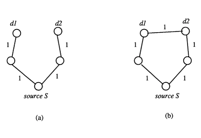
Wall’s thesis provides an in-depth comparison of low-cost and low-delay tree approaches to broadcast and selective broadcast (i.e. m ulticast).
d l d2
source S source S
(a)
Figure 2.1: Delay vs. Cost
In figure 2.1(a), the maximum delay in reaching destinations dt and dg, with respect to source 5, is 2 hops, and the total cost in reaching destinations di and dg is 4 hops from
S. In figure 2.1(b), destinations di and dg can be reached using ju st a single path from 5, with the maximum delay being in reaching dg, at 3 hops. The to tal cost, however, in reaching both destinations is 3 hops.
As is evident, building a minimum-delay delivery tree involves building a separate
shortest-path tree (SPT) from a source to each destination. However, a m inim um cost tree can be built using a single spanning tree.
Shortest-path trees (SPTs), whilst achieving minimal delay between a source and a destination(s), do not attem p t to minimize the to tal cost of distribution, but are relatively easy to com pute in a distributed manner, as we describe in the next section on Deering’s work.
It is im portant to put both “cost” and “delay” in a m ulticast context. “Cost” has implications regarding the scalability of m ulticast, and should be divided between the following three measures:
• the greater the cost of the delivery tree, the greater will be the overall transm itter costs. In our thesis ab stract we stated th a t optimizing tran sm itter costs was one of the prim ary benefits, or should we say goals, of multicast.
• cost associated with tree state information.
“Delay” , on the other hand, has relevance only to certain m ulticast applications, or, to be more precise, to users of those applications. Delay is not always an issue, for example, replicated database updating or querying, and resource discovery do not impose delay constraints. However, for real-time applications, such as voice conferencing [16], the delay experienced between a sender and the group’s receivers is critical, and it must not exceed certain bounds (on the order of a few hundred milliseconds for voice), otherwise the users of these applications become frustrated and disorientated.
It is worth mentioning, with respect to cost, the difference in complexity in building a minimum-cost tree th a t spans a subset of the vertices of a connected graph, i.e. a m inimum Steiner tree, and a minimum-cost tree th a t spans all of the vertices of the connected graph, i.e. a m inimum spanning tree. It was shown in [53] th a t building a minimum-cost steiner tree is NP-complete, whereas building a minimum spanning tree is not [75]. The point we are trying to make here is th a t building a single, minimum cost tree, spanning a group of receivers within an internetwork, is NP-complete.
Kou, Markowsky, and Berman [58] designed an algorithm , known as the KMB algo rithm , which offers a good approxim ation to a minimum Steiner tree. The cost of the resulting KMB tree averages 5% more than the cost of a minimum Steiner tree. However, the KMB algorithm requires complete network topology inform ation, and therefore is of no interest where large internetworks are concerned [60]. More recently, a routing algo rithm was proposed for connection-oriented networks, such as ATM, which under certain circumstances, is nearly as efficient as the KMB algorithm [51].
Wall set out to show th a t it is possible to build a single, “centre” rooted broadcast
algorithm for selective broadccist, and showed th a t, for a centre-rooted selective broadcast tree, the maximum delay bound remains the same.
The method he devised for finding the “centre” involved each node using its local information to calculate two values: the maximum delay to send a packet to its most distant destination; the average delay to send a packet to a random destination. Each node’s values were then pooled, and by means of a simple algorithm (see section 2.2) the “centre” chosen as the node either with the smallest maximum delay, or the node with the smallest average delay. Either of these criteria was considered a suitable candidate for the “centre” . We describe the election of the “centre” of Wall’s trees, and their construction in section 2.2.
There are various points we need to make to make clear how Wall’s early work on m ulticast diverges from the m ulticast model of today. Deering enum erated various prop erties th a t contribute to m ulticast’s flexibility and generality. Collectively, these properties comprise the Host Group Model [26]. Two of these: senders need not be members^ and
membership should be dynamic and autonomous^ conflict with Wall’s operational environ ment we have ju st described. Also, Wall’s algorithms have not made any provisions for network failures th a t lead to tree breakages, i.e. his algorithms are not robust. Therefore, Wall’s algorithms could not be used in to day’s m ulticast environment w ithout considerable adaptation.
Also, it may not always be desirable for all m ulticast applications th a t use a shared tree to have it centre-rooted. Take, for example, a lecture or seminar th a t is to be “audiocast” [16] to multiple recipients all over the world, as is often done on the MBONE. For such cases, where the principle sender is a t one site, it makes sense for the “centre” to be moved to, or near to, th a t site so th a t the centre-rooted tree emulates a shortest-path tree. Hence, time-critical applications such as audio- and video “broadcasts” can take advantage of the more desirable delay characteristics of a shortest-path tree, whilst actually being p art of a shared delivery tree.
Additional “centre nodes” , or cores as we will call them , may be placed in the same locality^ or alternatively, where the larger pockets of members are located. W ith regards
to this latter strategy, in the absence of a dynamic core placement algorithm (the pros and cons we will discuss later) and associated protocol, it is often difficult to know a t group- initiation time, where the larger pockets of members will be located in the internetwork. The purpose of additional cores in our model is for greater robustness - a shared delivery tree centred around a single router offers very poor fault tolerance, since the stability of the tree is completely dependent on a single router. Wall does not consider additional
“centres” in his trees. We add additional cores to make a tree more robust against failure, as well as protocol mechanisms to detect and recover from failures. These will be discussed in due course.
2.2
T h e C o n stru ctio n o f W a ll’s “C en tre-T rees”
W all’s m inim ization algorithm for constructing “centre-trees” actually involves all nodes in a graph attem pting to build a tree, with trees “killed off” when some b etter tree is seen. The resulting single spanning tree is a broadcast tree rooted a t some elected “centre” node. After our description of the broadcast tree construction, we explain how this technique was adapted slightly to accommodate selective-broadcast (i.e. m ulticast).
W all’s algorithm involves every node in a graph (network) broadcasting, by means of a multiply-addressed message, its centre criterion value. Each receiving node notes which edges (interfaces) it uses to forward the received message.
To reduce communication overhead, each node only forwards these so-called tree “con struction” messages if the message contains a lower criterion value than the lowest already recorded by th a t node. The prim ary candidate for the “centre” is the node with the lowest criterion value. Similarly, a node need only remember the edges (interfaces) over which it forwards a lowest-value “construction” message. O ther “construction” messages received are simply discarded.
way, a single spanning tree results, identified by the paths followed by the convergecast (acknowledgments), resulting from the lowest-value “construction” message.
Finally, so the network nodes know when the algorithm is complete, on receipt of an acknowledgement, the node th a t generated the corresponding “construction” message sends a final message announcing th a t tree construction is complete, which follows the branches of the new tree [100].
This algorithm becomes less optim al if nodes’ routing tables are inconsistent, if nodes fail, or if nodes re-start. Node failure is a problem, since, if a “construction” message includes a failed node in its address list, the neighbouring nodes will shunt it around indefinitely. Wall hats not made any provision for node failures in his algorithm [100].
R e-started nodes are an even harder problem. If a node has only recently re-started, a “construction” message originating in some remote p art of the network is unlikely to have included it in its address list, even though it probably should have. Again, Wall has not made any explicit provision for such a scenario in his algorithm, other th an to make some not-very-elegant suggestions as to how the problem might be remedied.
2 .2 .1 A d a p t a t io n fo r S e le c t iv e - B r o a d c a s t
Selective-broadcast was only a secondary goal of Wall’s thesis, and so his thesis is less ex tensive with regards to selective-broadcast (i.e. m ulticast). Nevertheless, Wall made sug gestions for extending his broadcast algorithms for the general case of selective-broadcast.
Wall attem pts to continually adapt a centre tree, so th a t, in spite of addition or removal of nodes (corresponding to new group members, and group members leaving, respectively), the “centre” remains optimally placed. This implies th a t an iteration of the minimization algorithm is required each time a node comes or goes. This further implies th a t highly dynamic group membership is likely to incur an excessive overhead in the form of network traffic and node processing.
message. For selective-broadcast, the algorithm requires additional communication: on receipt of a non-optimal message, the receiving node must reply to the sending (immediate neighbour) node with a “kill” message, which is propagated back as far as necessary, until it reaches a node th a t knows the corresponding tree is sub-optimal. A t this point, the “kill” message can be discarded. Similarly, a “kill” message is required when a “construction” message is received about a better tree - the “kill” is then forwarded over the branches of the old tree as far as necessary [100].
Finally, Wall suggests th a t, for the case of selective-broadcast, having the “centre” node outside the group of original nodes may result in more optim al trees. However, this would require identifying such candidate nodes early on, so as to include them in the minimization algorithm [100].
2.3
D e e r in g ’s W ork
Deering’s work [26] involved extending the three basic routing algorithms: single span ning tree, distance-vector^ and link-state, to achieve truncated-broadcast, and m ulticast, packet delivery. The basic algorithm s were designed to operate in a single-level, or flat,
internetwork (as they still do as of writing this thesis), but Deering also described how a combination of his algorithm s could be used in a very large internetwork th a t is structured as a hierarchy. Deering’s link-state and distance-vector algorithm s build source-rooted de livery trees, i.e. delivery trees em anating from the subnetwork directly connected to the source.
A truncated-broadcast tree is similar to a broadcast tree, but is pruned of /ea/subnetworks^. The advantage of such a tree over a broadcast tree is th a t it usually results in fewer packet copies being generated whilst incurring little extra overhead to establish.
In the context of multicast, a truncated-broadcast tree results in packets reaching subnetworks where no members exist. A multicast tree however, is one which spans only those subnetworks with group members, and routers and subnetworks on the path to
“leaf” subnetwork is one that is not used by any router to reach a particular source subnetwork.
subnetworks with group members. However, the establishm ent of a m ulticast tree requires th a t routers either maintain additional state, as is the case with distance-vector m ulticast routing, or engage in the exchange of group membership information with all other routers, as is the case with link-state m ulticast routing, as we will see below.
In term s of practical implementations, truncated-broadcast algorithm s for m ulticast packet delivery have become virtually obsolete because of the superfluous packet delivery they incur. Therefore, we will not describe Deering’s truncated broadcast algorithms. We will also not discuss his extensions to spanning-tree routing for multicast, since we are concerned with network layer multicasting - spanning-tree routing occurs between data-link layer bridges. These algorithm s are described in [26].
We therefore limit our discussion of Deering’s work to those algorithm s and associated protocols th a t are in use in the various portions of to d ay ’s Internet th a t have m ulticast capability - the so-called MBONE [32]. The MBONE consists primarily of routers^ run ning an instance of the distance-vector multicast algorithm known as the Distance- Vector Multicast Routing Protocol (D VM RP) [98, 26]. There are also a number of Autonomous Systems (AS’s) - primarily those whose unicast interior gateway protocol (IGP) is OSPF [68], which are running the Multicast Open Shortest-Path First (M -O SPF) protocol [69], based on the link-state multicast algorithm. M -OSPF regions interface to the M BONE by means of border router(s) specially conflgured to run an instance of each protocol.
W hilst both the distance-vector and link-state multicast algorithms were invented by Deering, M -OSPF was developed by Moy [70].
2 .3 .1 T h e D is t a n c e - V e c t o r M u lt ic a s t A lg o r it h m
DVM RP [98] is a protocol implementation of the distance-vector m ulticast algorithm pro posed by Deering [26]. This is a reflnement of Dalai and M etcalfe’s Reverse-Path For warding algorithm [22], proposed previously. The distance-vector m ulticast algorithm uses (destination, distance) vectors to advertise multicast-capable subnetworks to participating
^IP routers that route internetwork unicaist traffic are only just beginning to be manufactured with
in-built multicast capability. Currently, however, UNIX hosts running multicast protocol code make up
routers. These vectors are exchanged between neighbouring m ulticast-capable routers.
DVM RP is based primarily on Reverse Path Forwarding (RPF) - an algorithm devised by Dalai and Metcalfe [22] for internetwork broadcasting. Deering modified the R PF algorithm slightly to eliminate the possibility of multicast duplicates being sent across multi-access links [25].
The R PF principle is quite simple: if a packet arrives via a link th a t is the shortest-path back to the source of the packet, then forward the packet on all outgoing links (so-called
child links). Otherwise, discard the packet. DVM RP restricts the number of outgoing links to those which are not leaf subnetworks, unless a leaf subnetwork has group member presence, in which case a copy of the m ulticast packet will be forwarded over it.
DVM RP uses the R P F strategy which results in a shortest-path, sender-rooted, deliv ery tree being formed between a sender and the corresponding group members.
A number of packets from a new sender will actually span the truncated broadcast
tree rooted at the source. Only subsequently is the truncated-broadcast tree pruned back to become a true m ulticast delivery tree. For this to happen, a m ulticast packet for a particular (source, group) pair must first reach all leaves oi the truncated-broadcast tree. A router connected to a leaf subnetwork may generate a prune message for the corresponding (source, group) pair, provided none of its leaf subnetworks have any members on them. Prune messages are always sent one-hop back towards the source, provided the criteria ju st specified can be satisfied. Prune sta te in routers prevents traffic for th e corresponding (source, group) pair being forwarded on the links over which corresponding prunes have been received.
In summary, prune messages prevent m ulticast stream s from reaching those p arts of the internetwork th a t are not interested in receiving them . Prune state is “soft sta te ” , and is refreshed a t fixed intervals.
Should a group member appear on a previously pruned branch of a m ulticast tree, a mechanism was designed for quickly “grafting” back such a branch onto the tree. It requires th a t a router th a t previously sent a prune message for some (source, group) pair, send a graft message to the previous-hop router for th a t same (source, group) pair. If the receiving router in turn has sent a prune uptree, it would also be required to send a graft one-hop back towards the source, via the same path its prune was sent on. Thus, graft messages result in the removal of “prune sta te ” , thereby restoring a branch as p art of a m ulticast delivery tree.
2 .3 .2 T h e L in k - S t a t e M u lt ic a s t A lg o r it h m
M -OSPF is a protocol implem entation of the link-state m ulticast algorithm proposed by Deering [26]. Link-state routing requires th a t participating routers periodically monitor the state of all (or a subset) of their incident links. This statu s information is then tran s m itted to all other participating routers by means of a special-purpose flooding protocol.
In order to provide link-state multicast routing, the link-state routing algorithm was extended to allow the presence of a m ulticast group on a link to become p art of the “state” of th a t link. Thus, whenever a group appears or disappears, the state of th a t link changes, resulting in the designated router for th a t link flooding the new state to all other routers in the network.
Link-state m ulticast routers therefore, have complete knowledge of which groups are present on which links, throughout the domain of operation. Using this information, a router can use D ijkstra’s algorithm to com pute the shortest-path tree from any source to any group. Routers receiving m ulticast packets use this com putation to establish w hether they fall within the computed delivery tree with respect to the packet’s source, and if so, to which next-hop(s) a packet must be forwarded.
Routing multiccLsts between areas, and between AS’s, is much more complex and less efficient than intra-area multicasting, since group membership information is sent to the backbone area in the form of sum m ary link-state advertisements (LSAs), bu t the backbone area does not distribute this information to other areas. Hence, non-backbone areas are ignorant of other areas’ group memberships. All multicasts generated within an area are delivered to the area’s wild-card receiver(s), where they are discarded if group membership is exclusive to th a t area.
M -OSPF is the only m ulticast routing protocol to date th a t offers explicit support for multiple types o f service (TO S). IP datagram s can be labeled with any one of five types of service (TOS), namely: m inim um delay, m aximum throughput, m axim um reliability, m inim um monetary cost, and normal service. M -OSPF calculates a separate path for each {source^, destination, TOS} tuple, using D ijkstra’s algorithm. P ath s are calculated
on-demand and cached, thereby reducing the burden imposed on routers by spreading particular route calculations over time.
Finally, because each M -OSPF router calculates its own multicast delivery tree from the perspective of the source subnetwork, it knows the distance to each dow nstream sub network where group members are located. The router thus has the ability to immediately discard received m ulticasts th a t will never reach a particular receiver(s), based on the IP TTL in the received packet [69].
2.4
P r o to c o l In d ep en d en t M u ltica st (P IM )
The PIM m ulticast protocol is one of two m ulticast protocols (the other being the CBT M ulticast protocol) currently undergoing review in the Inter-D omain Multicast Routing
working group of the Internet Engineering Task Force (IETF). The IDM R working group was formed by the author as a result of his work identifying scalability problems in existing m ulticast routing protocols. The ultim ate goal of the IDMR working group is to propose a m ulticast routing protocol standard th a t can be used to achieve scalable
inter-domain m ulticast routing.
The PIM architecture was designed to establish efficient distribution trees for the cases where groups may be sp arsely o t dense/y distributed, i.e. PIM can be configured to adapt to different group and network characteristics. As a result, there are two PIM modes:
sparse m ode and den se mode.
As its name suggests, PIM is independent of whichever underlying unicast routing protocol is operating, unlike DVM RP or M -OSPF, which rely on particular features of their corresponding unicast routing protocols for their correct operation.
Dense-mode PIM is quite similar to DVMRP, but w ithout the unicast protocol depen dencies. For example, DVM RP uses the “poison reverse” technique [20] for leaf router detection. This involves advertising “infinity” for a source to the previous-hop router on the path to th a t source. The absence of such advertisements is an indication th a t a downstream subnetwork is a leaf. Furtherm ore, PIM routers do not calculate their set of outgoing child interfaces for each active source, but forward on all outgoing interfaces until such tim e as prune messages are received from a downstream router(s). Dense-mode PIM is thus said to be data driven.
For the case where group members appear on a pruned branch of the distribution tree, PIM dense-mode, like DVMRP, makes use of graft m essages to re-establish the previously pruned branch on the delivery tree.
PIM dense-mode is most likely to be the preferred mode of use in resource-rich envi ronments, such as a campus LAN, where a group is likely to be uniformly dense. Only in such an environment is d a ta driven flooding of multicasts, and subsequent pruning (and associated storage), acceptable.
Sparse-mode PIM, on the other hand, is the most likely mode for inter-domain (wide- area) multicasting. Sparse-mode PIM allows group members to receive m ulticast d ata either over a shared tree., which receivers must explicitly join first, or over a sh o rtest-path tree., which a receiver can create subsequently, in an attem p t to improve delay character istics between some active source, and itself. When a receiver creates a shortest-path to a particular source, it pru n e s itself off the shared tree for th a t (source, group) pair, but will continue to receive d a ta packets for the group over the shared tree from all other sources.
be several for robustness purposes. A new receiver need ever only join one RP if there are several, but a sender m ust send d a ta packets to each of the R P ’s, so th a t all receivers for the group receiving over the RP “see” the multicaats [24].
The motivation behind sparse-mode PIM is the desire to accommodate sparsely dis tributed groups, i.e. the type of group th a t is most prevalent in wide-area internetworks. W hilst shared trees, for the most part, scale more favourably than source-rooted trees, the designers of PIM wanted a receiver to have the choice to receive d a ta over a shortest-path tree, thereby optimizing delay. The trade-off in doing so is between routers keeping less state on a shared tree, or more state on a shortest-path tree. Also, as the number of shortest-path trees grow to a particular source, more overall bandw idth is consumed by the sum of the shortest-path trees than for a single shared tree.
As of writing, PIM is ’ongoing work’, and there remain issues which still need to be resolved, for example, w hat are the criteria for switching between a shared tree and a shortest-path tree? How is such a switch instrum ented? Furtherm ore, the PIM protocol is considerably more complex than existing IP m ulticast protocols.
The shared tree concept of multicasting in PIM is based on the Core Based Tree (C B T )
T h e C o re B a s e d T ree (C B T )
M u ltic a s t A r c h ite c tu r e
3.1
In tro d u ctio n
The Core Based Tree (C B T ) m ulticast architecture differs quite considerably from the existing IP m ulticast architecture in th a t it utilizes a single, shared delivery tree th a t spans a group’s receivers. CBT takes full advantage of various aspects of the existing multicast infrastructure, such as class D IP addresses, used for identifying m ulticast groups, and the Internet Group M anagement Protocol (IGMP), which is used by m ulticast routers to establish group member presence of directly-connected subnetworks.
A Class D address identifies a single host group. The class D address space is sepa rate portion of the IP address space, defined to be between 224.0.0.0 and 239.255.255.255 inclusive. IP address classes are defined in [80]. A thorough taxonomy of Internet ad dressing is provided in [36]. A small number of class D, or group, addresses are reserved for use by various routing protocols, such as 224.0.0.1 - the all-systems address, to which all m ulticast-capable UNIX end-systems are perm anently subscribed.
Whenever a host wishes to subscribe to a particular group, it sets its network interface so as to receive all packets whose destination address corresponds to a particular class D address. All end-systems wishing to participate in m ulticast must have a directly connected
multicast-capable router. This is tru e both for new IP m ulticast schemes like CBT and PIM, and older schemes like DVMRP.
IGM P is the protocol implemented in hosts and routers on LANs to monitor multicast group presence on a subnetwork. One router per LAN is elected as membership inter rogator. This election is implicit in the IGMP protocol and happens a t start-u p time. At fixed intervals the elected interrogator sends a non-group-specific membership query to the
all-systems m ulticast group. Hosts receiving this query do not respond immediately, but rather randomise their response over a ten second interval. On expiry of this interval a host sends a group membership report., once for each group it is affiliated to, and addressed to the corresponding group. All local multicast routers receive this report. If a group report arrives at a host before its own response interval expires, the corresponding mem bership report is cancelled a t the receiving host. In this way, the membership interrogating router learns of subnetwork group presence, and subnetwork bandwidth consumption due to membership reporting is minimized [26].
We have extended IGM P to reduce leave latency - the time between the last claim to a group on a particular subnet being relinquished, and the time group traffic is no longer forwarded onto th a t subnet. The details of our new IGM P version, and the motivations behind it, are given in section 5.1.11.
3.2
E x ten d in g M u ltic a s t’s E x istin g P ro p er ties
Deering, in [25], suggested th a t several im portant properties, originally conceived for the LAN m ulticast environment, be extended as desirable properties for internetw ork mul ticasting. These include: host group model conformance, high probability o f delivery o f multicasts, and low delay. We propose extending these properties further, given th a t the Internet is ever increasing in size [19] and heterogeneity, and given the fact th a t multicast is becoming increasingly popular on a global scale:
not exhibit good scaling properties across the full range of applications will have both limited usefulness and a restricted lifetime in the Internet.
• Routing algorithm independence. W hat we mean by routing algorithm independence is an independence from unicast protocol-specific features, A loose-coupled depen dency on underlying unicast routing is a necessity, since m ulticast routes are, or should be^, ultim ately gleaned from the unicast routing table.
Such independence is highly desirable for two reasons: it simplifies m ulticast routing across heterogeneous domain boundaries, and it allows for independent evolution of both unicast and multicast algorithms.
3.3
E x istin g M u ltica st A rch itectu re
DVM RP and M -OSPF comprise the protocols th a t are based on the existing multicast architecture. This architecture builds source based, shortest-path m ulticast delivery trees between a sender’s source subnetwork and the corresponding group receivers.
W hen the existing multicast algorithms were designed, it could not be foreseen to what extent m ulticast would grow in popularity. Today, if one looks a t the m ulticast tools available, such as “sd” , “vat” , and “wb” (all developed by Van Jacobson et al., LBL), and the protocols th a t have been developed to support real-time m ulticast traffic, such as RTP [87], it is clear th a t m ulticast capability has become a highly-desired feature in the Internet.
Below, we identify some of the shortcomings of the existing m ulticast architecture.
3 .3 .1 S o m e S h o r t c o m in g s o f t h e E x is t in g A r c h it e c t u r e
The implication of a m ulticast architecture based on source-rooted trees is one of scalabil ity. We will discuss the scalability of each of four m ulticast algorithm s in the next chapter.
^Until multiccist capability is installed in the internetwork infrastructure, multicast routing protocols
must implement their own routing daemon, thereby estabhshing a virtucil network, which is an overlay of
but it is worth mentioning briefly here, why the source-based architecture does not offer very favourable scaling characteristics for wide-area multicasting.
DVMRP, based on the distance-vector algorithm [26], periodically broadcasts packets everywhere when pruned branches of the m ulticast tree tim eout. If there are no receivers at the leaves of the tree, new prunes will be propagated up-tree. Thus, this incurs overhead, i.e. the storage of prune state, on routers th a t are not on the m ulticast tree.
M -OSPF can only be used in domains running OSPF [68]. M -OSPF broadcasts changes in group membership on a particular link, throughout th e domain of operation, since all M -OSPF routers have a complete topology map of the location of group members. This is necessary for the D ijkstra com putations, performed by each router, which com pute the m ulticast tree from the perspective of the active source. It should be obvious th a t the stor age of global membership information, as well as the overhead of D ijkstra com putations, does not scale to internetwork-wide multicasting.
3.4
C B T - T h e N e w A rch itectu re
3 .4 .1 A r c h it e c t u r a l O v e r v ie w
The Core Based Tree m ulticast architecture involves constructing a single delivery tree th a t is shared by a group’s members. M ulticast d a ta is sent and received over the same delivery tree, irrespective of the source.
The idea of core based trees for multicasting was derived from Wall’s work on broad casting and selective-broadcasting [100]. However, the similarity in his work and ours ends in the utilization of a shared tree. We provided an overview of the prim ary differences between Wall’s work and ours in chapter 2. We elaborate on these differences in section 3.6.
end o f a branch shall be known as a /e a /r o u te r on th e tree. Unlike W all’s trees, th e core need not be to p ologically centred^ betw een the nodes on the tree, since m u ltica sts vary in nature, and correspondingly, so should the form o f a g rou p ’s delivery tree. C B T is unique in th a t it allow s the m u lticast tree to be built to reflect the nature o f the application.
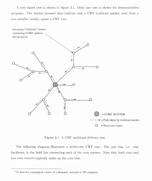
A core based tree is show n in figure 3.1. O nly one core is show n for d em on stration purposes. T h e d o tted arrowed lines in d icate how a C B T m u lticast packet, sen t from a non-m em ber sender, sp an s a C B T tree.
In com in g "m ullicast" p ack et
co n ta in in g C O R E address ^
and group-id.
Ç ) = C O R E R O U T E R
■ - - = Path taken by m u lticast packet
O = N o n -co re router
F igure 3.1: A C B T m ulticast delivery tree
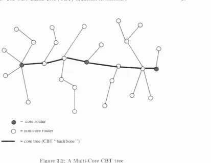
T h e follow ing diagram illustrates a m ulti-core C B T tree. T h e core tree, i.e. tree backbone, is th e bold line con n ectin g each o f the core routers. N o te th a t both core and non-core routers typ ically m ake up th e core tree.