316
Harmonic Reduction In Multilevel Inverter Based
On GA Optimization
Kishor bommassani, P. Ram Prasad
Abstract:This paper proposes a generalized formulation for Harmonic reduction-Pulse Width Modulation (HR-PWM) control suitable for high-voltage high-power cascaded multilevel voltage source converters (VSC) used in constant frequency utility applications. This utilizes the merits of the genetic algorithm (GA) in finding the optimal solution to the nonlinear equation system with fast and guaranteed convergence. This deals with different operation points for both five and seven level converters. The solution to the harmonic minimization problem using genetic algorithm optimization is determined
Keywords: Cascaded multilevel inverter, Hybrid Genetic Algorithm, Pulse width modulation, Selective Harmonic Elimination.
————————————————————
1
INTRODUCTION
Multilevel converters have drawn tremendous interest in recent years and have been studied for several high-voltage and high-power applications. Switching losses in these high-power high-voltage converters represent an issue and any switching transitions that can be eliminated without compromising the harmonic content of the final waveform is considered advantageous. The term multilevel starts with the introduction of the three-level converter. By increasing the number of levels in a given topology, the output voltages have more steps generation a staircase waveform, which approaches closely the desired sinusoidal waveform and also offers reduced harmonic distortion. One promising technology to interface battery packs in electric and hybrid electric vehicles are multilevel converters because of the possibility of high VA rating and low harmonic distortion without the use of a transformer. Harmonic Reduction-pulse-width modulation (HR-PWM) has been mainly developed for two- and three- level converters in order to achieve lower total harmonic distortion (THD) in the voltage output waveform. The main challenge associated with HR-PWM techniques is to obtain the analytical solution of the system for nonlinear transcendental equations that contain trigonometric terms which in turn provide multiple sets of solutions. Genetic algorithm has been recently introduced to optimize the sequence of the carrier waveform of the PWM as to minimize the THD and the distortion factor (DF) of output line voltage. An optimization technique assisted with a hybrid genetic algorithm was successfully applied to find the switching transitions (i.e. ., switching angles) of the HR-PWM ac/ac converter. More recently, a general genetic algorithm using Matlab GA optimization Toolbox was applied to solve the same problem of HR-PWM.
However, the solutions to the equal dc sources and with the fundamental frequency switching method which has lower degrees of freedom for specifying the cost function compared with the proposed PWM method for the same physical structure. Furthermore, hybrid genetic algorithm is applied to stepped multilevel converter with non equal dc sources in. As the primary limitation (disadvantage) of the stepped modulation techniques lies in its very narrow modulation index range, several works have been attempting to overcome this shortcoming. Specifically, proposed a modulation technique that widens the modulation index by swapping the polarity of some levels so that a low modulation index can be obtained and maintaining the fundamental switching technique. A new active harmonic elimination technique was recently introduced to the line frequency method aiming to eliminate higher order of harmonics by simply generating the opposite of the harmonics to cancel them. However, the disadvantage in that is that it uses a high switching frequency to eliminate higher order harmonics. Other approaches have also been reported, including one where the harmonic elimination is combined with a programmed method, and another where multilevel HR-PWM defined by the well-known multi carrier phase-shifted PWM (MPS-PWM) was proposed in, where the modulation index defines the distribution of the switching angles, and then the problem of HR-PWM is applied to a particular operating point aiming to obtain the optimum position of these switching transitions that offer elimination to a selected order of harmonics. By effectively solving the harmonic elimination problem with large number of switching angles, the HR-PWM method can generate high-quality voltage waveform as well as less switching frequency as compared to other modulation techniques. Fig.(1) Shows the structure of a single-phase multi-level cascaded inverter that consists of series connection of H- bridge inverter units. Each unit has its own separated dc source (SDCS), which may be obtained from an ultra-capacitor, battery, fuel cell, solar cell, etc. In order to generate the multilevel voltage waveform, the ac terminal voltages of different H-bridge inverters are connected in series and the overall output voltage van is given by the sum of H-bridge voltages. i.e., van =v1+ v2+ v3+ v4 + v 5.
______________________
Kishor bommassani, P. Ram Prasad
M.tech student, Department of EEE, Swaranandhra
College of Engineering and Technology, Narsapur- 534 280
Associate professor, Department of EEE,
Swaranandhra College of Engineering of
Technology, Narsapur- 534 280
Fig1: Cascaded H-Bridge Multilevel Inverters
Each full bridge inverter can generate three different dc voltage levels of + Vdc, O, and - Vdc in its ac terminal, which depends on the state of four power switches: Q1, Q2, Q3 and Q4. The number of levels of output phase voltage
m in a cascade multilevel inverter is m =2s + 1, where s is
the number of SDCs.
II. ESTIMATION OF SWITCHING ANGLES
As per the Fourier theorem the periodic output voltage V𝜔t) can be described by a constant term plus an infinite
series of sine and cosine terms of frequency nω, where n is
an integer. Therefore V (𝜔t) in general, can be expressed
as
𝑓 ωt =𝑎0
2 + 𝑎𝑛cos n ωt + 𝑏𝑛sin nωt ∞
𝑛=1 , (1)
Because of the output voltage of the multilevel inverter is
quarter wave symmetry, the Fourier series constants 𝑎0 and
𝑎𝑛an become zero and only bn is to be calculated. The
value of bn is found using the equations (2)
bn= 1 𝜋 𝑉0
2𝜋
0 (𝜔t) sin 𝑛𝜔t d(𝜔t), (2)
Fourier series of the quarter-wave symmetric H-bridge multilevel inverter output waveform is written as given in
equation (6) in which 𝜃s are the optimized switching angles,
which must satisfy the following condition
𝜃1< 𝜃2 < 𝜃3… … 𝜃𝑠< 𝜋
2 (3)
The method to solve the optimized harmonic switching angles will be explained in this section. From equation
1. The amplitude of dc component equals zero.
2. The amplitude of all odd harmonic components including fundamental one, are given by
ℎ 𝑛 =4𝑉𝑑𝑐
𝜋 cos 𝑛𝜃𝑘 𝑠
𝑘=1 (4)
3. The amplitude of all even harmonics equal zero. Thus, only the odd harmonics in the quarter-wave symmetric multilevel waveform need to be eliminated. The switching
angles of the waveform will be adjusted to get the lowest THD in the output voltage
ℎ 𝑛 =4𝑉𝑑𝑐
𝑛𝜋 [cos 𝜃1+ cos 𝜃2+ cos 𝜃3+ ⋯ ]
If needed to control the peak value of the output voltage to be V1 and eliminate the fifth and seventh order harmonics, the modulation index is given by
M=𝑛𝑉1
4𝑉𝑑𝑐 the resulting harmonic equations are
4𝑉𝑑𝑐
𝜋 [cos 𝜃1+ cos 𝜃2+ cos 𝜃3+ cos 𝜃4…..]= 𝑉1 (5)
cos 5𝜃1+ cos 5𝜃2+ cos 5𝜃3+ cos 5𝜃4….= 0 (6)
cos 7𝜃1+ cos 7𝜃2+ cos 7𝜃3+ cos 7𝜃4….= 0 (7)
Equation (5) is rewritten as
cos 𝜃1+ cos 𝜃2+ cos 𝜃3+ cos 𝜃4… . = 𝑀 (8)
Each H-bridge inverter unit has a conduction angle Which is calculated to minimize the harmonic components the conduction angles are the factors determining the amplitude of the harmonic components. This paper deals with a H-bridge cascaded inverter because its multi-level output voltage can be almost sinusoidal. In that case the conventional method can eliminate the dominant harmonics except for the fundamental wave. In multi level inverter ‗n‘ dc sources are needed so that the dc voltage levels are chosen so as not to generate the dominant harmonics while achieving the desired fundamental voltage. This is a system of three simultaneous equations with four unknowns
𝜃1, 𝜃2, 𝜃3, 𝜃4. .. .These values are found by solving the
simultaneous equations (5-7).
III. GA TOOLBOX
Genetic Algorithm (GA) is a method used for solving both constrained and unconstrained optimization problems based on natural selection, the process that drives biological evolution. GA repeatedly modifies a population of individual solutions. At each step, GA selects individuals at random from the current population to be parents and uses them to produce the children for the next generation. Over successive generations, the population "evolves" towards an optimal solution. GA uses three main rules at each step to create the next generation from the current population:
Selection rules select the individuals, called parents that
contribute to the population at the next generation.
Crossover rules combine two parents to form children for
the next generation
Mutation rules apply random changes to individual parents
to form children.
Calling the function ‘ga’ at the Command Line To use
318
[x fval] = ga (@fitness fun, nvars, options)
Where
@fitnessfun is a handle to the fitness function.
nvars is the number of independent variables for the fitness
function.
Options is a structure containing options for the genetic
algorithm. If you do not pass in this argument, GA uses its default options. The results are given by
x — Point at which the final value is attained
fval — Final value of the fitness function Using the function
GA is convenient if you want to Return results directly to the MATLAB workspace Run the genetic algorithm multiple times with different options, by calling ga from an M-file.
Fig2: flow chart of GA
Using GA Tool The Genetic Algorithm tool is a graphical user interface that enables you to use the genetic algorithm without working at the command line. To open it, enter
gatool. at the MATLAB command prompt. The tool opens
as shown in the Fig.2. To use the GA tool, the following information is entered,
Fitness function — The objective function is to minimize.
Enter the fitness function in the form @fitnessfun, where fitnessfun is an M-file that computes the fitness function.
Number of variables — The length of the input vector to
the fitness function. Enter constraints or a nonlinear
constraint function for the problem in the Constraints pane.
If the problem is unconstrained, leave these fields blank. To run the GA, click the Start button. The tool displays the results of the optimization in the Status and results pane. We can change the options for the genetic algorithm in the Options pane.
Fig.3: GA toolbox
IV. MULTI-LEVEL INVERTERS
Simulation circuit for Three phases 3-level inverter: Simulation of 3-level and 5-level cascaded multilevel inverter is done using simulink from MATLAB. IGBTs are chosen as switching device for simulation, since it has more features than the other power semiconductor devices.
Three-Level converter: A typical three-phase inverter
designed in half-bridge topology (Figure 3) allows for an output voltage waveform that can switch between two voltage levels only. The topology in Figure 1b, by contrast, allows for an output voltage waveform that switches through three voltage levels, which is why this topology is also known as three-level inverter topology. We will now analyse the principle behind a three-level inverter in order to ascertain the differences between it and a conventional 2-level inverter [1]. For a three-phase three 2-level inverter a structure similar to that used with 12 electronic devices (IGBT) is needed (see Fig 3). Each phase will switch across three voltage levels (+Vdc/2, 0, -Vdc/2).
In a structure such as this the maximum voltage across the IGBT is limited to half the maximum DC link voltage (Vdc/2). This is down to the fact that the IGBTs are connected to the neutral point (MP) by two fast diodes called neutral clamp diodes.
Fig5: Simulation circuit for three phase 3-level inverter
Fig6: Simulation Result For Three Phase 3-Level Inverter
GA results:
Objective function value: 1.19683556479E-4
The optimal firing angles are:
α_1=33.85and α_2=177.5
Fig.7: Best Fitness and Individual Plots
Five-Level Converter: In this case, the five-level output
waveform is produced by connecting two H-bridge cells in series. First, it is assumed that each cell operates at a frequency of three times the fundamental; therefore, there are three switching angles per quarter-cycle at the output
voltage of each cell (i.e., N1 = N 2 = 3) producing an overall
six angles per quarter-cycle of the five level waveform (i.e.,
N = 6). The optimization technique is applied to this case to
find the optimal switching angles that eliminate five lower harmonics and controlling the fundamental. It is interesting to note that even though the solution does not exist for the whole region of modulation index, multiple sets of solution have been found as plotted. The investigation to define the optimal set that might have lower harmonic distortion is beyond the scope of this paper as its application dependant and will be addressed in future work.
Fig8: Simulation circuit for three phase 5-level inverter
0 0.1 0.2 0.3 0.4 0.5
-50 0 50
Selected signal: 25 cycles. FFT window (in red): 3 cycles
Time (s)
0 5 10 15 20
0 2 4 6 8
Harmonic order Fundamental (50Hz) = 80.79 , THD= 16.39%
M
a
g
(
%
o
f
F
u
n
d
a
m
e
n
ta
l)
0 10 20 30 40 50 60 70 80 90 100
0 5 10
Generation
F
it
n
e
s
s
v
a
lu
e
Best: 0.00011968 Mean: 0.00041263
1 2
0 50 100 150 200
Number of variables (2)
C
u
rr
e
n
t
b
e
s
t
in
d
iv
id
u
a
l
Current Best Individual
320
Fig9: Simulation result for Three phase 5-level inverter
Fig.10: Best Fitness And Individual Plots
GA results:
Objective function value: 0.026125005156022996 The optimal firing angles are,
𝛼1=65.96⁰, 𝛼2=205.93⁰,𝛼3=294.92⁰and 𝛼4=294.92⁰
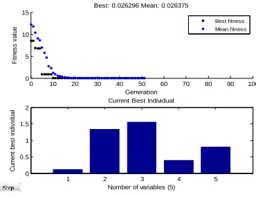
Simulation results for Single Phase 15-Level Inverter:
Simulation circuit for Single phase 15-level inverter is shown in fig. 11, which consist of 7casacded bridges. Simulation result for Single phase 15-level inverter is
shown in fig. 12, best fitness and individual plots is
shown in fig. 13.
Fig11: Simulation circuit for Single phase 15-level inverter
Fig .12 : Simulation result for Single phase 15-level inverter
Fig.13: best fitness and individual plots
0 0.1 0.2 0.3 0.4 0.5
-100 0 100
Selected signal: 25 cycles. FFT window (in red): 3 cycles
Time (s)
0 5 10 15 20
0 1 2 3 4 5
Harmonic order Fundamental (50Hz) = 106.3 , THD= 13.34%
M
a
g
(
%
o
f
F
u
n
d
a
m
e
n
ta
l)
0 10 20 30 40 50 60 70 80 90 100 0
5 10 15
Generation
F
it
n
e
s
s
v
a
lu
e
Best: 0.026296 Mean: 0.026375
1 2 3 4 5
0 0.5 1 1.5 2
Number of variables (5)
C
u
rr
e
n
t
b
e
s
t
in
d
iv
id
u
a
l
Current Best Individual
GA Results:
Objective function value: 0.026187093375983773
The optimal firing angles are,
𝛼1=25.96⁰, 𝛼2=45.453⁰,𝛼3=55.243⁰,𝛼4=74.854⁰,
𝛼5 = 85.543⁰,𝛼6= 97.622⁰and 𝛼7 = 117.847⁰
Comparison table for simulation results: THD values of 3,5and 15 level inverter using PWM technique and Genetic Algorithm are given in Table1.
Table1: Comparison of simulation results
V. CONCLUSION
A generalized formula of Harmonic Reduction-Pulse width Modulation (HR-PWM) suitable for high-power high-voltage cascaded multilevel converters with equal dc voltage sources was proposed and demonstrated in this project. Using this GA optimal firing angles have been determined for various multi-level cascaded inverter topologies. These optimal firing angles are used for triggering the power
devices (IGBT/diode).With this switching angles
approximate sinusoidal output voltage and current waveforms with minimum amount of Total Harmonic Distortion (THD) have been achieved. The percentage of THD obtained in the output of multilevel inverter topologies using PWM technique is compared with that obtained in the output of multilevel cascaded inverters in which advanced Genetic Algorithm optimization technique is used. It is observed that nearly 70-80% THD in the output has been reduced by using Genetic Algorithm optimization technique as compared to that obtained from inverter topologies using PWM technique.
VI. REFERENCES
[1]. J. Kumar, B. Das and A. Pramod, ―Selective
Harmonic Elimination Technique for a Multilevel Inverter,‖ Proceedings of Fifteenth National Power Systems Conference (NPSC), Bombay, December 2008, pp. 608-613.
[2]. A. Sarwar, M. S. J. Asghar, Imdadullah and S. K.
Moin Ahmed, ―Development of Solar PV Based Grid Connected Inverters,‖ Proceedings of International Conference on Electrical Energy System & Power Electronics, Chennai, April 2009, pp. 1172-1177.
[3]. L. M. Tolbert, J. N. Chiasson, Z. Du and K. J.
McKenzie, ―Elimination of Harmonics in a Multilevel Converter with Non equal DC Sources,‖ IEEE Transaction on Industry Applications, Vol. 41, No. 1, 2005, pp. 75-81. doi:10.1109/TIA.2004.841162.
[4]. L. M. Tolbert, J. N. Chiasson, D. Zhong, and K. J.
McKenzie, ―Elimination of harmonics in a multilevel converter with non equal dc sources,‖ IEEE Trans. Ind. Appl., Vol. 4, No. 1, pp. 75–82, Jan./Feb. 2005.
[5]. Distributed Power Generation Systems with DC
Voltage Sources,‖ International Conference on
Renewable Energies and Power Quality,
Saragossa, 2005.
[6]. A. Myrzlk and M. A. Johanna, ―Novel Inverter
Topologies for Single-Phase Stand-Alone or Grid Connected Photo-Voltaic Systems,‖ 4th IEEE International Conference on Power Electronics and Drive Systems, Denpas-sar, October 2001, pp. 103-108.
[7]. A. Sarwar, M. S. J. Asghar, Imdadullah and S. K.
Moin Ahmed, ―Development of Solar PV Based Grid Connected Inverters,‖ Proceedings of International Conference on Electrical Energy System & Power Electronics, Chennai, April 2009, pp. 1172-1177
No. of
levels Phase
THD% using PWM technique
THD% using Genetic Algorithm
3-level Three 35.01% 16.39%
5-level Three 25.80% 13.34%