R E S E A R C H
Open Access
Multichannel simultaneous uplink and
downlink transmission scheme for flexible
duplexing
Adrian Kliks
*and Paweł Kryszkiewicz
Abstract
The idea of adaptive usage of uplink frequency resources for other purposes, such as downlink data transmission, has attracted researchers for many years. As an extension of the conference paper on the same subject, this article discusses the concept of applying a multichannel simultaneous uplink and downlink transmission scheme for flexible duplexing, where the middle part of the so-called uplink component carrier is used for downlink data delivery. The realization of such an idea is based on the adaptive change of the transmit/reception mask at the base stations and/or mobile devices and the application of the non-contiguous transmission scheme. Beside a theoretical analysis, this paper provides the calculation results of the interference rise in the system.
Keywords: Flexible duplexing, Non-contiguous transmission, Interference, LTE/LTE-A, 5G systems
1 Introduction
The problem of asymmetric traffic, typical for modern wireless networks, can be solved in various ways depend-ing on the applied duplexdepend-ing schemes between uplink (UL) and downlink (DL) data delivery. In time division duplexing (TDD), a fragment of the frequency spectrum is utilized in both directions of data transmission (i.e., from base station (BS) to mobile terminal (MT), and from MT to BS), and the split between UL and DL is done in the time domain. As the wireless standards typically pro-vide a very detailed time hierarchy (i.e., transmitted bits are organized into frames, bursts, chunks), it can be fore-seen that asymmetric traffic can be easily managed by the application of adaptive allocation of more time slots to that direction which needs to serve higher traffic. Such an approach has been discussed in, e.g., [1–4].
Contrarily, in the classical frequency division duplex-ing mode (FDD), the data between BS and MT can be
*Correspondence: [email protected]
This paper is an extension of the conference paper by the same authors presented at CROWNCOM 2016 and entitled Simultaneous Uplink and Downlink Transmission Scheme for Flexible Duplexing (Kliks and Kryszkiewicz, Simultaneous uplink and downlink transmission scheme for flexible duplexing, 2016)
Faculty of Electronics and Telecommunications, Poznan University of Technology, pl. M. Skł odowskiej-Curie 5, 60-965 Poznan, Poland
delivered continuously in the time domain in both direc-tions if needed, but the split between UL and DL is realized in the spectrum domain, i.e., dedicated fragments of the frequency spectrum are assigned to each transmis-sion direction. In such a case, the problem of asymmetric traffic can be solved by allowing data transmission in a selected direction in both bands. In other words, UL band can be utilized for DL transmission and vice-versa. Some interesting discussion can be found in, e.g., [5, 6]. It is also worth noticing here that the frequency bands dedicated for UL and DL transmission are separated by a dedicated frequency gap guaranteeing enough isolation between the transmit and receive signals. This isolation is required, as the problem of efficient canceling of strong interference at the reception interface echoed from the transmitted one is not mature enough today, although much progress has been achieved in the area of wireless full-duplex trans-mission [7, 8]. These observations have to be considered while realizing the concept of adaptive utilization of both frequency bands for data delivery only in one direction.
In our work, we concentrate on FDD scheme with particular attention given to LTE/LTE-A systems. Our motivation behind such a selection is to provide new technological solutions, while keeping the backward com-patibility with current standards. In other words, one may notice that many of the existing wireless standards
(including practical deployments of LTE) are based on FDD mode. Thus, it is highly expected that the existing infrastructure will be utilized as effectively as possible, and flexible usage of frequency bands in such a scenario can be one of the interesting solutions. Moreover, we assume that the amount of traffic in the DL direction is much higher than in the opposite direction, as this represents a typical situation in crowded areas where the role of the dominating service is played by mobile video stream-ing [9]. Clearly, an opposite situation is also possible (one can consider mass events where many persons decide to upload the photos or videos), but it is not as popular as the previous one. Finally, in such a context, the selection of LTE-based systems is natural, as this is the technology that permanently supersedes 3G systems in many places in the world. However, the application of flexible duplexing (FD) in FDD-LTE is not straightforward, due to the con-tinuous transmission of control signals in PUCCH in the UL band (PUCCH stands for physical uplink control chan-nel). It means that (potentially) every time there is a useful signal present in the uplink band, and it is not possible to allocate the whole UL band for downlink transmission without interfering to the base station.
One of the possible solutions in such a case is to apply the TDD mode in the uplink band [1]. In other words, the whole DL band is utilized for delivering data from BS to MT only (so the classic FDD transmission scheme is kept in the DL band), but the UL band is split in time into equal time slots which can be adaptively assigned to UL or DL depending on the current traffic in both directions. In this context, it is worth mentioning the further developments in this topic, known as the TDD Enhanced Interference Management and Traffic Adaptation (eIMTA) [10, 11], also standardized in release 12 of LTE [12]. Here, the split between the uplink and downlink data is considered to be flexible and modified adaptively to the observed traffic.
In the approach discussed in this paper, we propose to use the uplink bands in a highly flexible way, so that the split between uplink and downlink traffic depends mainly on the current user demands and assumed priori-ties. We consider simultaneous data transmission in both uplink and downlink directions, implementing advanced adaptive transmission/reception filtering for out-of-band attenuation. In general, this technique allows us to uti-lize the middle part of the uplink component carrier for DL transmission. Clearly, such a transmission scheme results in an interference rise observed inside the serv-ing and all surroundserv-ing cells. Thus, in order to evaluate the proposed scheme, we have analyzed its impact on the interference boost observed by other users (mobile termi-nals or base stations). Based on that analysis, we propose to apply simple resource allocation techniques for further enhancements in the proposed scheme, as well as we dis-cuss the backward compatibility of that study. The key
idea of the paper is to check the possibility of utilizing of all available uplink resources for downlink transmis-sion, assuming that some of these uplink resources are already occupied by legacy UL transmission and need to be protected. This approach is highly flexible and can be used as a solution for advanced spectrum utilization in 5G networks. Moreover, the proposed technique can also guarantee backward compatibility with 4G systems. Thus, in order to check the correctness of the proposed approach (i.e., simultaneous uplink and downlink trans-mission) and its backward compatibility, we intentionally modeled a 4G-like scenario where uplink control data are transmitted at the edges of the uplink band.
As the paper is an extension of the work presented in [13], the key novelties of this contribution can be summa-rized as follows:
• First, we have applied the proposed flexible duplexing (FD) scheme in an advanced case, i.e., when multiple component carriers are applied in the system. In particular, we focus on the carrier aggregation scenario when the mobile network operator utilizes two adjacent component carriers for uplink transmission, and the flexible duplexing algorithms are applied for all component carriers
simultaneously. Although we provide the analysis for two component carriers, let us note that it can be easily extended to other carrier aggregation schemes, where more component carriers are treated jointly.
• Second, we have calculated the maximum allowable values of the transmit power for small cells which work in flexible duplexing mode and which are deployed among macro base stations.
• Third, we have provided the analytic analysis of the interference existing in the considered scheme, i.e. when there is simultaneous UL and DL transmission in the UL channel; comparing to the previous works, we have considered the legacy systems, where Orthogonal Frequency Division Multiplexing (OFDM) signal (in DL) is interfering with uplink SC-FDMA (single-carrier frequency division multiple access) transmissions; our intention is to discuss the flexible duplexing transmission mode in a case when backward compatibility is guaranteed.
• Fourth, we have simulated the impact of the parallel UL transmission on the efficiency of considered flexible duplexing scheme.
the transmit/reception masks. This discussion is followed by the theoretical derivations of the interference power observed in the considered multichannel scheme. In the next section, we discuss two use cases, i.e., when one and more component carriers are used. The analysis is fol-lowed by a presentation of the obtained numerical results for numerous simulation scenarios. Finally, we provide the concluding remarks.
2 Flexible duplexing for 4G and 5G—case with
single-component carrier 2.1 TDD mode applied in uplink band
The concept of flexible utilization of unused frequency resources in FDD-based wireless communication systems is one of the immediate solutions that appeared during the discussion on the effective management of asymmet-ric traffic in current and future networks. As introduced in the previous section, various schemes have been con-sidered so far (please see the discussion also in, e.g., [1]), but the most focus has been put on TDD-based solutions. In such a case, the UL band is utilized following the time division duplex mode, where for certain time slots, the UL channel is used for downlink data transmission. Clearly, such a scheme results in an interference increase observed by other system users (for example, by those located in the surrounding cells). In order to minimize the impact of this phenomenon, quite often, (almost) ideal synchroniza-tion between cells is considered. This issue is illustrated in Fig. 1, where a frame consisting of 10 subframes is shown. In the upper part, the classic case is shown, where the whole UL band is used only for UL transmission. In such a case, one can ideally assume the lack of interfer-ence between the neighboring cells (in the figure, we used the names cell A and cell B). In the middle part of the figure, some arbitrarily selected UL subframes are used for DL data transmission, causing interference to the adja-cent cells. The problem is more severe if there are some
synchronization problems between the cells, as shown in the bottom part of the figure.
2.2 Use cases for transmission scheme with single-component carrier
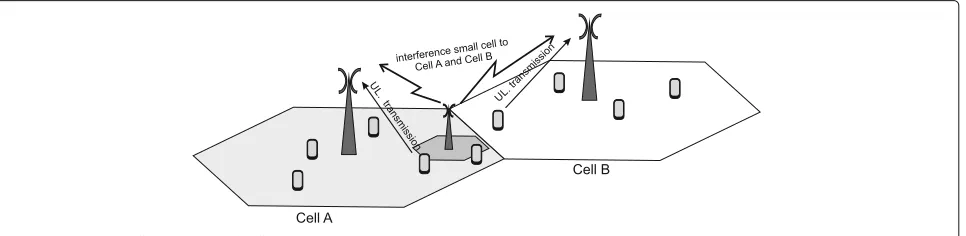
There are various practical use cases considered in the context of flexible duplexing that can be found in the lit-erature. In order to illustrate the idea we show two of them below. First, as discussed in the previous subsection, one can apply flexible duplexing at the macro cell level. Thus, it is the macro base station that decides to assign some of the slots for downlink transmission, and such a transmission scheme is unique within the whole cell. The interference is then observed in the neighboring cells— please see Fig. 2. Another case includes the presence of small cells, i.e., there is more flexibility in assigning the subframes for UL or DL transmission, as this decision can be made either at the macro, or small-cell level. In the latter case, interference is induced into both serving and neighboring sites, as shown in Fig. 3.
2.3 Proposed simultaneous flexible duplexing scheme for single-component carrier transmission scheme Let us now consider an FDD-LTE-based system operat-ing in both macro cells (hereafter denoted as cell A and cell B) with the frequency reuse factor close to unity; the application of the soft frequency reuse can be considered as well, but it does not influence the idea investigated here. In such a case, the uplink component carrier is used, broadly speaking, for user data delivery (realized in PUSCH, standing for physical uplink shared channel) and for uplink control information transmission (typically per-formed via PUCCH). It is important to notice that the PUCCH data are transmitted using small frequency seg-ments located on the borders of the component carrier. In the considered scenario, we focus on the case when the UL channel (in cell B) is used only for conveying control
Fig. 2Two macro cell scenario
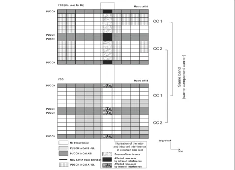
information, and there are no user data to be delivered to the base station. At the same time, cell A is using the middle part of its own component carrier for downlink transmission, causing some interference rise. The idea is illustrated in Fig. 4, where the first seven subframes are managed in the way described above. We foresee that the proposed scheme can be extended to a more flexible sit-uation where the fragment of the UL band will also be used for user data transmission (as shown in the last three subframes); this is a topic for further investigation. Please notice that we have also intentionally illustrated the pres-ence of interferpres-ence observed within the serving cell (cell A), as the resource blocks used for PUCCH delivery in cell A will be affected by the DL transmission in the middle of the band.
The key concept proposed by us is to apply advanced, adaptive spectrum shaping algorithms originally consid-ered to be used in non-contiguous multicarrier trans-mission schemes [14]. These solutions can guarantee a significant reduction of unwanted out-of-band emission even in a very narrow frequency band at a reasonable complexity. Moreover, these algorithms can be applied at the beginning of a frame, allowing for a precalcula-tion of the required spectrum masks (filter shapes). The moments when the new spectrum masks have to be changed within the cell are indicated by solid bold vertical lines in Fig. 4.
2.4 Sources of interference in non-orthogonal OFDM/SC-OFDM systems
The interference power in the considered scenario at the SC-OFDM receiver (cell B base station/eNodeB) comes from two sources [15]:
• Out-of-band (OOB ) radiation of the DL/UL transmitter-this is mostly the effect of sinc-like subcarrier spectrum. As it has been shown in [15], each subcarrier in the time domain can be
represented by a complex sinusoid windowed using a rectangular window. However, there are a number of spectrum shaping methods designed in order to reduce OOB radiation power, e.g., [16, 17]. The simplest one is to use so-calledguard subcarriers [15] by modulating subcarriers closest to the currently utilized spectrum bandwidth with zeros (i.e., subcarriers close to the PUCCH band in cell B are zeroed). Another source of OOB radiation is the high Peak-to-Average Power Ratio (PAPR) of an OFDM transmission carried using a nonlinear front-end. However, it can be effectively reduced using PAPR minimization or predistortion techniques [18]. The method that we use in this paper to reduce OOB radiation at TX side is an Optimized Cancellation Carriers Selection (OCCS) method [16]. Out of all allocated data subcarriers, some subcarriers are
Fig. 4Proposed scheme for simultaneous flexible duplexing [13]
reserved for, so-called, cancellation carriers (CCs). Based on a set of complex data symbols modulating a given OFDM symbol, their frequency response in the OOB region is calculated. As CCs have non-zero frequency response in the same region (sinc-like shape of each subcarrier’s spectrum), their values are adjusted using least squares approximation so that total OOB radiation power is minimal. Most importantly, in [16] an algorithm for finding optimal CCs location is proposed. Additionally, for a given OFDM symbol, the optimization is limited to a single matrix-vector multiplication where matrix is complex valued, constant for a given system configuration and vector consists of data subcarriers symbols.
• Limited selectivity of OFDM/SC-OFDM receiver-in a case when there is no user data transmission in the uplink (only the control channel is present), the middle part of the UL component carrier is empty, and only the resource blocks at the border convey useful data. However, the DFT operation is carried at the receiver onN consecutive incoming samples cut out from a stream of incoming samples. As such, time-domain windowing withN -length rectangular window is used. The reception filter characteristic of a single subcarrier has a sinc-like shape. If there is a DL signal (transmitted as stated above in the middle of the UL band) observed by the cell B receiver, high power sidelobes of a sinc function will cause interference on the used subcarrier (conveying control information). In order to overcome this problem, time-domain windowing or filtering should be applied at the receiver.
The interference phenomenon existing between both systems can be described analytically. The approach presented below is a new one as it describes interference between OFDM and SC-FDMA1. In [19] the interference was calculated between two different radio access tech-nologies (e.g., OFDM and GFSK). Let us note, however, that in case of two FDM bases systems (SC-FDM and OFDM in our scheme), these two signal can be mutually orthogonal depending on the time and frequency syn-chronization between the considered systems. The inter-ference analysis between two OFDM systems has been addressed, e.g., in [20], but that paper did not consider the interference when SC-FDMA transmission is applied. Additionally, it has used analog representation of OFDM modulation, while digital OFDM is a common standard. In the following, we provide the theoretical analysis of the interference phenomenon in the scenario considered in this paper for simultaneous flexible duplexing.
Let us assume that the SC-FDM/OFDM transceivers utilize the N point discrete Fourier transform (DFT) with occupied subcarriers constituting set I. Each ele-ment ofI belongs to set of available subcarrier indexes
{−N/2,. . .,N/2 −1}. In our analysis, we can consider only two consecutive symbols, i.e., 0th and -1st, with-out loss of generality. Each symbol has a cyclic prefix of theNCPsamples. The interfered receiver utilizesNpoint IDFT and as such can span samples out of maximally two consecutive OFDM symbols. Most importantly, we will assume the signal is generated by SC-FDM transmit-ter and received by OFDM receiver. However, the shift in the transmitter by half of subcarrier spacing can be
calculate interference power caused by OFDM transmitter to SC-FDMA receiver.
Let us note also that there is no need to consider here the DFT precoding applied normally at SC-FDMA trans-mitter. According to Parseval theorem, the interference power in the receiver after FFT block (applied as well in OFDM receiver) will be the same as after utilization of IFFT (specific for SC-FDMA).
Having the above assumptions in mind, the mth
sample of the 0th SC-FDMA symbol (where m ∈
{−NCP,. . .,N−1}) is defined as
where dn(0) is either QAM/PSK symbol (also after DFT precoding, if considered) transmitted at subcarrier indexedn, and the shiftn+12 is due to the application of the legacy SC-FDMA scheme, where such a shift in fre-quency is introduced. Such a time-domain signal passes through the multipath channel of L taps with impulse responseh(l); the mobility of the users is also considered. The received signal normalized to subcarrier spacing is defined as:
where ν stands for the Deppler shift. Let us denote the time instant of the beginning of the receiver DFT win-dow as m, so the signal observed at nth subcarrier is
where wm defines the reception window shape applied at the receiver side (e.g., rectangular, Hanning). Two cases are possible, first, when there is no inter-symbol interference (i.e., the receiver can be treated as to be
symbol-synchronizedand there is only one symbol within
the reception window; it is denoted hereafter as case A); and second, when there is lack of synchroniza-tion and fragments of two consecutive symbols are observed within the duration of the reception window (denoted hereafter as case B). In the following, we will consider these two cases separately, starting from the former one.
2.4.1 Case A-no inter-symbol interference
If we consider the case whenm ∈ −NCP+L−1; 0, so there will be no inter-symbol interference, then:
Rn,m =
Assuming that the data on each subcarrier are not corre-lated, i.e., the expected valueE
dn(0)dm∗(0)
=0 forn=m, the power onnth subcarrier can be computed as:
ERn,m2
application of the rule for the sum of a geometric series, one may find that:
N−1
2.4.2 Case B-presence of inter-symbol interference
Now, let us consider more complex situation, when there are samples originating from two consecutive symbolss(0)
and s(−1) within the duration time of the receive win-dow. In such a case, some sort of inter-symbol interference will be observed. Let us consider the exemplary situa-tion when L equals 1. In this casem will be defined as
m∈<−N−NCP+1;−NCP−1>. For other values of L the following derivations constitute the approximate solu-tion, where the influence of multipath channel is included. In consequence, the signal observed atnth subcarrier and for the time-stampmis defined as:
Rn,m =
Using the relation defined in (5) one may write that:
Rn,m=
As previously, we assume that the data symbols within each OFDM symbol and between the two consecu-tive symbols are uncorrelated, i.e., the expected value
Ed(np)dm∗(q)
=0 forn=m, and for any integer values of
pandq. In consequence,
If we assume the special case of rectangular window, the above formula can be simplified as follows:
ERn,m2
= 1 N2
n∈I
d(n−1)2H
n+1 2
2
×
sinπ−m−NCP
N n+12−n+ν sinNπ n+12−n+ν
2
+ 1 N2
n∈I
d(n0)2H
n+1 2
2
×
sinπm+NCP
N +1 n+12−n+ν sinπNn+12−n+ν
2
.
(15)
3 Flexible duplexing for 4G and 5G—extension to
multiple component carrier case
Let us now consider the case where the mobile network operator utilizes more than one component carrier in its wireless cellular network. The prospective transmission
schemes do not differ in general from the ones presented in previous section and illustrated in Figs. 2 and 3. The only difference is in the number of utilized component carriers which is now greater than one. Such a scenario is shown in Fig. 5. One may observe the presence to two adjacent component carriers, which are utilized in the FDD mode for flexible duplexing by applying the trans-mission scheme proposed in this work. Moreover, for the sake of clarity, we have emphasized the intra- and inter-cell interference phenomenon in a certain time slot by indicating the resource blocks being the source of inter-ference and the affected resource blocks.
3.1 Application of non-contiguous multicarrier transmission
Let us observe that from the perspective of the downlink transmission, it is a natural consequence that the consid-eration of more than one component carrier immediately entails the possibility of application of non-contiguous multicarrier schemes for data transmission [14, 19]. In such a scheme, the concatenation of two component carri-ers can be treated as a joint wide spectrum for multicarrier
signal transmission, where selected subcarriers are not used to protect the present uplink signals. Such subcar-riers cancelation (switch off ) results in narrow gaps in the spectrum of the transmitted signal—in the considered case of flexible duplexing, these are the PUCCH channels that have to be protected.
3.2 Cooperation between base stations
As one of our goals is to guarantee backward compatibil-ity (so there would be no need to modify existing legacy hardware, i.e., MT devices), it is also worth analyzing the impact of radio access network on the performance of pro-posed flexible duplexing scheme. In the context of 4G net-works, one may observe that the neighboring base stations (eNodeBs) are connected via well-known X2 interface which allows for efficient coordination of these base sta-tion and applicasta-tion of various advanced algorithms, e.g., inter-cell interference cancelation. For flexible duplexing, coordination between the base stations (eNodeBs, but in a broader sense also potentially between eNodeBs and small cells) entails accurate allocation of unused resource blocks for downlink transmission. If reliable communica-tion between the eNodeBs will be guaranteed, then the dedicated radio resource management algorithms can be applied which will assign UL resources for DL transmis-sion in such a way that the activity of MT located in a considered cell and in the neighboring cells is taken into considerations.
4 Simulation results
In order to evaluate the proposed scheme, we would like to measure the impact of the interference induced to other users due to the application of the proposed flexible duplexing scheme (i.e., when the advanced spec-trum shaping proposed in [16, 17] is implemented) in both scenarios—when one or more component carriers are used in the system. We consider the presence of var-ious receivers in the system, ones that are equipped with the proposed spectrum shaping algorithms, and others that can be treated as classical, legacy LTE devices (base stations or mobile terminals). The idea here is to guar-antee backward compatibility with the existing devices. As the key novelty of this paper is the extension of the work presented in [13] to more than one component carri-ers, we focus on the transmission scheme where multiple component carriers are used.
4.1 Power spectral density analysis—extension to multichannel case
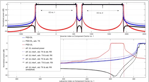
As the results for the single-component case are promis-ing, let us now evaluate the effectiveness of the proposed solution when the non-contiguous multicarrier transmis-sion is applied for two adjacent component carriers. For each component carrier, the details of the transmit signal
are analogous to the setup of the signal described in [13] for single-component carrier case, as we again assume the compatibility with LTE standard. In particular, SC-OFDM (UL) and SC-OFDM (DL) occupying a maximum of 2 component carriers (CCs), 20 MHz bandwidth each, are considered. It is assumed that both CCs are generated and received using a single processing chain utilizing 4096-point FFT/IFFT and spanning 61.44 MHz bandwidth (subcarrier spacing is equal to 15 kHz). This approach is advantageous over separate processing of each CC as it guarantees orthogonality between CCs. The frequency separation between both CCs is calculated to be 19.8 MHz according to [21], Section 5.7.1A. Both systems transmit their signals in dedicated time slots (0.5 ms duration each) composed of 7 OFDM/SC-OFDM symbols. While the first symbol in a slot utilizes 320 samples with CP, the rest are 288 samples long, each. It is assumed that there is no synchronization, neither in time, nor in frequency domain (as it is the most challenging scenario) between UL and flexible DL transmissions. The results were generated for 1000 OFDM/SC-FDMA frames shifted randomly in time. The frequency misalignment between both systems is 0.5 subcarrier spacing.
Let us remind that the maximal number of resource blocks (RBs) in the considered scheme is 100 per CC. In the case of no data transmission in UL, only PUCCH is transmitted on both ends of the available band, i.e., RBs indexed 50 and −50 in each CC. In the proposed scheme, unused resource blocks in between utilized UL channels can be used by cell A for its DL transmission. In Fig. 6, normalized power spectral densities (PSDs) of UL and DL signals are shown using solid lines. While the top figure shows whole 61.44 MHz bandwidth, the bottom plot zooms the left edge of CC no. 1. Cell A transmission utilizes RBs with indexes{−48,. . .,−1, 1,. . ., 48}in both CCs, i.e., a contiguous band around the DC subcarrier (0th RB is not used). Signals are normalized to have equal received power per utilized RB. The OOB emission from the DL transmission in band of the uplink at the level of around−25 dB. As these results are very close to the ones for single-component carrier case [13], one may conclude that the influence of adjacent channels (component carri-ers) is negligible for the outer (i.e., distant from adjacent component carrier center frequency in frequency domain) PUCCH channels. However, also the impact of the adja-cent component carriers on the inner PUCCHs is rather negligible. It is due to the most significant impact origi-nating from the subcarriers closes to the edge of the DL signal spectrum.
Fig. 6Normalized PSDs of UL and DL transmitted signals, effective interference/useful signal power at cell B base station (receiver)—multichannel case. Onlylowerfrequency edge is shown at thebottomfigure [13]
and receiver (in UL) do not apply advanced spectrum filtering—this case is denoted by dashed blue line. Next, two cases where either transmitter apply OCCS method (dashed black) or receiver apply 512-sample-long Han-ning windowing (dashed blue with plus markers). Finally, the case where both, transmitter and receiver, apply ded-icated algorithms for interference minimization (dashed black with plus signs). Again, as in the previous case with single-component carrier, the best results have been achieved in the situation when dedicated algorithms have been applied at both sides of the system. One may observe that again, the observed interference power is around
−45 dB less than the observed power of the wanted PUCCH signal. It also shows that the impact of the addi-tional component carriers is negligible and that the pro-posed FDD non-contiguous multicarrier scheme can be efficiently applied to flexible duplexing with carrier aggre-gation (i.e., when many component carriers are used). Most importantly, the analytical formula (derived in previ-ous chapters) for received interference power was utilized for standard TX and standard RX case and it is aligned with simulation results. In order to obtain this result interference power observed at a given subcarriernwas averaged over all possible RX windows positions m. If there is some other knowledge on both systems timing relations (e.g., there are only some possible shifts between
received frame and RX window), this calculation should be modified using still E[|R(n,m)|2] values. Flat chan-nel was assumed (H(n)=1) and no carrier frequency offset other than standard shift by 0.5 subcarrier spacing.
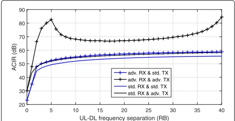
4.2 Adjacent channel interference ratio analysis—extension to multichannel case
In this section, we analyze the adjacent channel inter-ference ratio (ACIR) as a good metric used for the assessment of the ratio of wanted power to the inter-ference power from the other bands. Mathematically, ACIR is the function of the adjacent channel leakage ratio (ACLR, used to characterize the transmitter) and the adja-cent channel selectivity (ACS, used to characterize the
receiver), i.e., ACIR = 1
ACLR−1+ACS−1. In our case, it is calculated as a ratio of FD signal power at the BS RX antenna to the summarized power of interfering signal observed over 12 subcarriers utilized by a given PUCCH channel at the output of FFT block in SC-OFDM receiver. Utilizing results in Fig. 6, it can be calculated for advanced RX and advanced TX by integrating PSD-DL, adv. TX
power and dividing it by result of integration ofeff. UL interf., adv. TX & adv. RXover a−50th RB.
closest to the utilized UL band increases both ACLR and ACS. Let us note that such an approach is compliant with the existing LTE TX/RX technology, although it decreases the achievable rate (as some subcarriers are not utilized). The efficiency of this approach is considered here. In Fig. 7, ACIR values of the standard and advanced TX/RX technologies are shown as the functions of frequency sep-aration between the UL and DL signals. Although this value addresses ACIR for a single PUCCH RB, differences between 4 observed PUCCH RBs were negligible. Results are shown only for one of these RBs.
It is shown that when the PDSCH and PUCCH overlap (frequency separation equal 0), ACIR equals about 25– 30 dB. The situation changes rapidly when guard subcarri-ers are used. Even in the case of a standard transmitter and receiver, the introduction of a single empty resource block between the UL and DL bands (frequency separation equal to 2, this is the case shown in Fig. 6.) increases ACIR to 45 dB. In the case of advanced TX and RX utilization (with the spectrum shaping algorithms discussed previ-ously), the frequency separation of 2 RBs results in ACIR equal to 66 dB. It means that by proper signal process-ing, e.g., spectrum shaping at the transmitter [16, 17] and windowing at the receiver [15] together with the appli-cation of guard subcarriers, a significant ACIR increase can be achieved. It is worth explaining why the curve rep-resenting ACIR for an advanced transmitter and receiver rises steeply for low frequency separation, and then it falls down. Such behavior is observed due to the specificity of the OCCS method which reduces the OOB most signifi-cantly in the adjacent subcarriers. For higher distance (in frequency) between modulated subcarriers and protected band, its performance is limited. Please notice also that for very high distance (in frequency), the performance increases again—it is due to the fact that the total num-ber of used CCs relative to the considered numnum-ber of data subcarriers is high, so the OOB in wide spectrum can be precisely minimized.
0 5 10 15 20 25 30 35 40
UL-DL frequency separation (RB)
20 30 40 50 60 70 80 90
ACIR (dB)
adv. RX & std. TX adv. RX & adv. TX std. RX & std. TX std. RX & adv. TX
Fig. 7Adjacent Channel Interference Ratio for a single PUCCH RB vs UL-DL frequency separation (0 RBs mean that PUCCH and PDSCH overlap) with standard and advanced TX/RX
4.3 Interference from MT UL transmission to MT receiving DL transmission using FD scheme
Although our main concern is not to distort macro cell UL transmission by means of DL transmission using FD scheme, the other sources of interference can be identi-fied as well. Transmission in PUCCH (within the given cell and in neighboring cells) will cause interference to MTs receiving DL transmission. It will be particularly be sig-nificant as both MTs are located close in space. Using the same assumptions as previously normalized PSDs, inter-ference power and wanted signal power are shown in Fig. 8. The wanted signal (dashed blue line) is received from RBs −48,. . .,−1 and 1,. . .,48 (at each CC) with normalized power on each subcarrier equal 0 dB. The PUCCH transmission is carried in RBs−50, 50 (at each CC). The interference power for standard receiver (dashed red line) is higher than the PSD in the wanted signal frequency range. This is the result of high sidelobes of subcarrier spectrum at TX and high sidelobes of RX fil-ter characfil-teristic. However, affil-ter application of Hanning windowing at RX side the interference goes down to the level defined by PSD plot. It is assumed that the UL TX is backward compatible. As such, no advanced TX side processing is considered. Most importantly, the analytical interference power definition was derived as previously, i.e., average over all possiblem values. Theoretical val-ues (red circles), defined analytically in previous chapters, are aligned with simulation results. The measured ACIR value equals 25.3 and 22.3 dB, for the system with and without advanced RX processing, respectively. This calcu-lations assume only one PUSCCH channel is used (−50 RB in CC 1) and that the wanted FD band spans all 192 RBs (defined above). The ACIR can be increased if needed by turning off RBs located closely in frequency to PUCCH transmission, i.e., guard subcarriers can be utilized.
4.4 Influence on transmission opportunity in neighboring cell in multichannel scheme
In the most rigorous approach, the given base station (i.e., the one that applies proposed flexible duplexing scheme) can transmit according to the proposed scheme only if all other cells’ transmissions are not deteriorated (in prac-tice, some deterioration should be acceptable). According to Table 8.2.1.1–6 in [21], the minimum SINR that should allow for PUSCH transmission using QPSK modulation and13coding rate is−0.4 dB. However, PUCCH reception should even be possible for lower SINR values, namely,
-1000 -500 0 500 1000 1500 2000 2500
subcarrier index vs Component Carrier no. 1
-50 -40 -30 -20 -10 0
Normalized power (dB)
-640 -630 -620 -610 -600 -590 -580 -570 -560 -550
subcarrier index vs Component Carrier no. 1
-45 -40 -35 -30 -25 -20 -15 -10 -5 0
Normalized power (dB)
PSD-DL
PSD-UL
eff. DL received power
eff. DL interf., std. TX & std. RX
eff. DL interf., std. TX & adv. RX
eff. DL interf., std. TX & std. RX (analytical)
Fig. 8Normalized PSDs of UL and DL transmitted signals, effective interference/useful signal power at user equipment—multichannel case. Only
lowerfrequency edge is shown at thebottomfigure
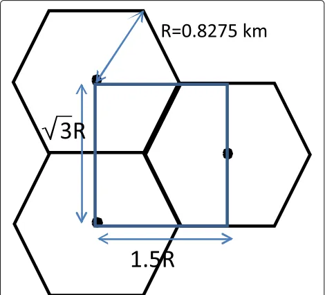
evaluate this issue, the effective cell radius has been cal-culated using the COST 231 model for carrier frequency
f = 2 GHz, base station antenna heightHA = 30 m, mobile terminal antenna heighthMT = 1.5 m, and mobile terminal and BS gainsGMT = 0 dBi andGBS = 18 dBi, respectively, (according to [22]). Assuming the mobile ter-minal transmit power isPMT = 23 dBm and thermal noise power in 300 K increased by a noise figure (NF) of 5 dB [22], standard cell radius equalsRA = 0.83 km.
For the same system parameters, the interference plus noise power can be increased by 3.4 dB while transmitting PUCCH (instead of PUSCH), as discussed above. It can be calculated that the effective interference power from cell A to standard cell UL should be equal or lower than
−93 dBm per a given PUCCH RB.
Let us now assume the case where the base stations are deployed according to the scheme presented in Fig. 9. The considered system composes of 3 standard cells uti-lizing in a given time slot only PUCCH. We assume also the application of full-frequency reuse strategy, i.e., in every cell both component carriers are used. Locations of standard base stations in [X,Y] coordinates are [0,0] km, [0,1.43] km and [1.24,0,72] km, i.e., the radius of the cell is set toR = 0.8275 km. In Fig. 10, the maximal allowed power of FD transmission is calculated in 600 points between these BSs. For each location pathloss to each UL BS is calculated. For each case−93 dBm of effective interference power per PUCCH RB can be introduced, as
derived above. The interference propagation between BSs is assumed to follow log-distance path loss model with pathloss exponentγ equal to 2 or 2.5. Although previously
GBS = 18 dBi was used, now it can be assumed that both BSs (i.e., interfered and interfering) are not directed at each other.GBSequal to 10 dBi at both BSs is used.
Fig. 10Maximal FD transmission power vs location in the presence of 3 PUCCH-receiving BSs
It is visible that the lowest allowed FD BS power is obtained for ACIR=30 dB andγ = 2. In this case, inter-ference propagates easily using line-of-sight propagation between both BS. ACIR value shows there are not many GSs between FD and UL transmission or advanced TX & RX is not used. Still 10 dBm FD transmission is possi-ble if the BSs are distanced by more than 500 m. On the other hand, higher pathloss (γ = 2.5) or ACIR=55 dB allows to use higher FD transmission power or to transmit in locations closer to UL-utilizing BSs. For ACIR=55 dB andγ = 2.5, it is possible to place FD-utilizing BS about 50 m apart from PUCCH-receiving BS and transmit using 35 dBm power.
The previous examples shown that a small cell utilizing the proposed FD scheme can operate relatively close to standard BSs without disrupting PUCCH reception. The other question is if nearby PUCCH transmission from MT will allow reception of DL transmission by another MT working in FD mode. In order to check this scenario, it is assumed that small-cell BS operates in the loca-tion allowing for highest transmit power, i.e., 37.8 dBm. Its coordinates are [0.43,0.69] km. The antenna gain is
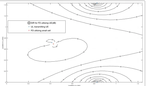
GBS = 18 dBi andGMT = 0 dBi for base station and MT, respectively. It is assumed that propagation conditions between both MTs and between femto BS and MT fol-low log-distance path loss model with pathloss exponentγ equal to 3. As an example, the interfering MT is located at the cell edge, with coordinates [0.83 0] km. As such max-imal power of 23 dBm is used to transmit PUCCH signal. Assuming ACIR between PUCCH transmission and FD utilized band equals 22.3 dB (result provided above), the calculated signal-to-interference ratio at MT RX is shown in Fig. 11. Although the SIR value decreases as MT gets closer to the interfering MT (blue circle), it is anyway
high in most of the observed area. This is caused by rel-atively high BS transmit power (37.8 dBm), TX antenna gain (18 dBi), and some frequency separation (ACIR equal to 22.3 dB).
In a more advanced case up to 3 MTs can cause inter-ference at the same time (3 PUCCH RBs). Next test was done for 3 MTs interfering at the same time located at cell edges with coordinates [0.83 0] km, [0.83 1.4] km, and [0.41 0.72] km. The resultant flexible duplexing MT SIR is shown in Fig. 12. It is visible that the SIR values decreased; however, still relatively high value is achieved.
5 Conclusions
10
Location in x (km) 0
Location in y (km)
SIR for FD utilizing UE(dB)
UL transmitting UE
FD utilizing small cell
Fig. 11Calculated signal-to-interference ratio at MT RX in case of nearby single UL transmission
10
Location in x (km) 0
Location in y (km)
SIR for FD utilizing UE(dB)
UL transmitting UE
FD utilizing small cell
of them are used simultaneously, due to the utilization of some context information, such as position of the macro base stations.
Endnote
1Let us remind that our goal is to analyze the propose
flexible duplexing scheme ensuring backward compatibil-ity with legacy LTE/LTE-A standard, where SC-FDMA is applied for UL. Moreover, in an SC-FDMA mode, there is a so-called half-subcarrier shift introduced in UL, so the signal in baseband is symmetric with regard to the zero (DC) subcarrier.
Acknowledgements
This work has been funded by the EU H2020 project COHERENT (contract no. 671639).
Competing interests
The authors declare that they have no competing interests.
Publisher’s Note
Springer Nature remains neutral with regard to jurisdictional claims in published maps and institutional affiliations.
Received: 10 November 2016 Accepted: 11 May 2017
References
1. L Wan, M Zhou, R Wen, in2013 IEEE Globecom Workshops (GC Wkshps). Evolving LTE with flexible duplex (IEEE, Atlanta, 2013), pp. 49–54 2. H Liu, Y Jiao, Y Gao, L Sang, D Yang, inTelecommunications (ICT), 2015
22nd International Conference On. Performance evaluation of flexible duplex implement based on radio frame selection in LTE heterogeneous network (IEEE, Sydney, 2015), pp. 308–312
3. 3GPP: Performance evaluation of dynamic TDD reconfiguration. R1-120196, Samsung, Feb. (2012). 3GPP
4. 3GPP: Evaluation of TDD traffic adaptive DL-UL reconfiguration in isolated cell scenario. R1-120059, Huawei, HiSilicon, Jan. (2012). 3GPP
5. YS Soh, TQS Quek, M Kountouris, G Caire, Cognitive hybrid division duplex for two-tier femtocell networks. IEEE Trans. Wirel. Commun.12(10), 4852–4865 (2013)
6. P Pirinen, inComputer Aided Modelling and Design of Communication Links and Networks (CAMAD), 2015 IEEE 20th International Workshop On. Challenges and possibilities for flexible duplexing in 5G networks (IEEE, Guildford, 2015), pp. 6–10
7. JI Choi, M Jain, K Srinivasan, P Levis, S Katti, inProceedings of the Sixteenth Annual International Conference on Mobile Computing and Networking.
MobiCom ’10. Achieving single channel, full duplex wireless
communication (ACM, New York, 2010), pp. 1–12. http://doi.acm.org/10. 1145/1859995.1859997
8. A Sabharwal, P Schniter, D Guo, DW Bliss, S Rangarajan, R Wichman, In-band full-duplex wireless: challenges and opportunities. IEEE J. Sel. Areas Commun.32(9), 1637–1652 (2014)
9. CISCO: Cisco visual networking index: global mobile data traffic forecast update, 2014–2019. White paper, 11–520862 (2015). http://www.cisco. com/c/en/us/solutions/collateral/service-provider/visual-networking-index-vni/mobile-white-paper-c11-520862.html. Accessed 07 June 2017 10. V Pauli, Y Li, G Eiko Seidel in Nomor Research GmbH, Munich: Dynamic
TDD for LTE-A and 5G. White paper (2015). http://www.nomor.de/home/ technology/white-papers/dynamic-tdd. Accessed 07 June 2017 11. 3GPP: TR 36.828 - Evolved Universal Terrestrial Radio Access (E-UTRA):
further enhancements to LTE time division duplex (TDD) for
downlink-uplink (DL-UL) interference management and traffic adaptation (Release 11) (2012). 3GPP
12. 3GPP: TS 36.300 - Evolved Universal Terrestrial Radio Access (E-UTRA) and Evolved Universal Terrestrial Radio Access Network (E-UTRAN): overall description (release 12) (2015). 3GPP
13. A Kliks, P Kryszkiewicz, inCognitive Radio Oriented Wireless Networks - 11th International Conference, CROWNCOM 2016, Grenoble, France, May 30 - June 1, 2016, Proceedings. Simultaneous uplink and downlink transmission scheme for flexible duplexing (IEEE, 2016), pp. 192–203
14. H Bogucka, P Kryszkiewicz, A Kliks, Dynamic spectrum aggregation for future 5G communications. IEEE Commun. Mag.53(5), 35–43 (2015) 15. T Weiss, J Hillenbrand, A Krohn, FK Jondral, inVehicular Technology
Conference, 2004. VTC 2004-Spring. 2004 IEEE 59th,vol. 4. Mutual interference in OFDM-based spectrum pooling systems (IEEE, Milan, 2004), pp. 1873–18774
16. P Kryszkiewicz, H Bogucka, Out-of-band power reduction in NC-OFDM with optimized cancellation carriers selection. IEEE Commun. Lett.17(10), 1901–1904 (2013)
17. P Kryszkiewicz, H Bogucka, in2012 IEEE Wireless Communications and Networking Conference (WCNC). Flexible quasi-systematic precoding for the out-of-band energy reduction in NC-OFDM (IEEE, Paris, 2012), pp. 209–214
18. P Kryszkiewicz, A Kliks, H Bogucka, in2015 International Symposium on Wireless Communication Systems (ISWCS). Obtaining low out-of-band emission level of an NC-OFDM waveform in the SDR platform (IEEE, Brussels, 2015), pp. 66–70
19. P Kryszkiewicz, A Kliks, H Bogucka, Small-scale spectrum aggregation and sharing. IEEE J. Sel. Areas Commun.34(10), 2630–2641 (2016)
20. Y Medjahdi, M Terré, DL Ruyet, D Roviras, Interference tables: a useful model for interference analysis in asynchronous multicarrier transmission. EURASIP J. Adv. Signal Process.2014(1), 54 (2014)
21. 3GPP: TS 36.104 V12.5.0 (2014-09) - Technical Specification Group Radio Access Network; Evolved Universal Terrestrial Radio Access (E-UTRA): base station (BS) radio transmission and reception (release 12) (2014). 3GPP 22. EPT: Report 40: Report from CEPT to European Commission in response to
![Fig. 1 Examples of flexible duplexing schemes in TDD mode [13]](https://thumb-us.123doks.com/thumbv2/123dok_us/929649.1112855/3.595.59.544.566.715/fig-examples-flexible-duplexing-schemes-tdd-mode.webp)
![Fig. 4 Proposed scheme for simultaneous flexible duplexing [13]](https://thumb-us.123doks.com/thumbv2/123dok_us/929649.1112855/5.595.58.541.87.296/fig-proposed-scheme-for-simultaneous-flexible-duplexing.webp)