[N.G. Ghazey* et al., 4(10): October, 2017]
ISSN: 234-5197
Impact Factor: 2.715
I
NTERNATIONAL
J
OURNAL
OF
R
ESEARCH
S
CIENCE
&
M
ANAGEMENT
EFFECT OF CURRENT, PULSE DURATION, AND PULSE INTERVAL FOR
DIFFERENT ELECTRODES SHAPE ON ELECTRODE WEAR RATE IN EDM
Nagham Ghanem Ghazey*1 and Dr. Shukry Hammed Aghdeab2*1M.Sc Research Scholar, Production Engineering & Metallurgy Department, University of
Technology, Baghdad, Iraq
2 Ph.D Research Scholar, Production Engineering & Metallurgy Department, University of
Technology, Baghdad, Iraq
DOI: 10.5281/zenodo.1006763
Keywords: Electrical discharge machining, Electrode shape, Electrode wear rate, Factorial design.
Abstract
The process of electrical discharge machining (EDM) includes thermal erosion of the workpiece by a series of sparks from an electrode depending on electrical source of energy. The workpiece and the electrode are submerged in a dielectric fluid. This paper presents an experimental investigation for studying the effect of electrodes shape using (flat, conical, and round) bottoms, currents of (10, 20, and 42 A), pulse duration of (25, 50, and 75 µs) and pulse interval of (37, 12, and 3.5 µs) on electrode wear rate (EWR). A series of experiments was carried out using 27 specimens, workpiece of AISI 1060 steel material with thickness of 2 mm, electrode of extra high leaded brass material with diameter of 16 mm, and transformer oil as dielectric liquid. The relationship between machining parameters (current, pulse duration, and pulse interval) and electrode wear rate (EWR) was found for each electrode shape and a comparison between electrodes shape was done to know which electrode shape gives lowest EWR. From experimented results, it is revealed that for most of runs conical electrode gives lowest EWR as compared with flat and round electrodes. The factorial design was used to develop a mathematical model to create a plot that shows the effect of electrodes shape and predict the values of EWR by the Minitab statistical software (MSS).
Introduction
Electrical discharge machining (EDM) is an electro-thermal machining process, because it uses electrical energy to generate electrical spark and thermal energy of the spark to remove workpiece material [1]. EDM is the process of machining the workpiece by melting and vaporizing it, using controlled sparks occur between an electrode and a workpiece in a tank of a dielectric fluid [2]. Workpiece material of EDM could be difficult to cut in conventional machining with striking properties like high bending stiffness, low thermal expansion, high strength, and better fatigue characteristics such as ceramics, super alloys, and composites [3]. Materials of the electrode and workpiece should be electrically and thermally conductive to perform the process [4]. The mechanical properties of electrode and workpiece materials like (tensile strength, grain size, hardness, and transverse rupture strength) have no effect on machining performance. The thermo physical properties like (melting and boiling temperature, thermal expansion, and electrical and thermal conductivity) have considerable effect. The mechanical properties of electrode affect the manufacturing of the electrode [5, 6]. The performance of the process relies on the electrode in its design, fabrication method, and material [7-9]. The process uses a physical tool with geometry that represents geometric feature or impression of the obtained hole [4]. Intricate shapes, delicate or thin fragile sections, and very small workpieces can be produced with EDM without deforming them [10]. This process doesn't need to direct physical contact between the electrode and the workpiece so there is no exerted mechanical stress on the work piece [11]. This process is utilized in production of the moulds, punches, dies, and finished parts of automotive and aerospace industry and surgical components [12].
Yan B.H. et al. (2000) [7] researched in rotary EDM using Al2O3/6061Al composite workpiece and copper
[N.G. Ghazey* et al., 4(10): October, 2017]
ISSN: 234-5197
Impact Factor: 2.715
I
NTERNATIONAL
J
OURNAL
OF
R
ESEARCH
S
CIENCE
&
M
ANAGEMENT
discharge machining (micro-EDM) with and without ultrasonic vibration to make micro holes and finish them with the use of a cylindrical and helical micro electrodes with tungsten carbide material in a high nickel alloy. It was concluded that micro-EDM with ultrasonic vibration with the use of a helical electrode reduces the EDM gap more, gives better shape accuracy, and the machining time has been decreased than others. Ahsan Ali Khan et al. (2009) [14] discussed the influence of electrode shape of die sinking EDM on mild steel workpiece material using copper electrode. The selected shapes of the electrodes were round, square, triangular, and diamond having constant cross-sectional area of 64 mm2. It has been concluded that the round electrode leads to
highest MRR and lowest EWR, then square, triangular and diamond electrodes followed. Also the diamond electrode produces highest wear ratio (WR), then triangular, square and the round electrodes followed. In addition, the round electrode gives lowest average surface roughness (Ra), followed by square, triangular and the
diamond electrodes. Oguzhan Yilmaz and M. Ali Okka (2010) [15] investigated electrical discharge machining of hole drilling using single-channel electrode (having one cavity) and multi- channel electrode (having three cavities) made of brass and copper materials on Inconel alloy. It has been concluded that brass electrode with single-channel has the highest MRR and the lowest electrode wear ratio (EWR). In addition, brass and copper electrodes having multi- channel gives less hardness of the drilled hole. G. D’Urso et al.
(2011) [16] worked on influence of process parameters (current, frequency, pulse duration, and electrode rotation speed) using micro- EDM on Titanium plates using cylindrical and tubular carbide electrodes. The geometrical characteristic of the micro-holes was investigated such as (the overcut and the taper rate). It has been discovered that tubular electrode led to better conditions (increasing in MRR, decreasing in wear rate, decreasing in overcut, and increasing in taper rate). Abhishek Singh et al. (2013) [17] investigated the effect of electrode geometry in electric discharge drilling process on MRR using copper electrodes with four bottom shapes (solid cylindrical, chamfered, conical and helical) on Al6063/10% SiC composite workpiece. The experimental results showed that the conical electrode produced the highest MRR, the chamfered and solid cylindrical electrodes produced nearly the same MRR, and the helical electrode produced the lowest MRR.
Saad Hameed Najem and Maan Aabid Tawfiq (2014) [18] worked on die sinking EDM machine on stainless steel workpiece, two copper electrodes (multi 4-channels and multi 7-channels). Results showed that the electrode having 7-channels gives lowest EWR. M.Manohar et al. (2014) [19] focused on electrodes having different bottom profiles like (convex, concave and flat) of copper rod with 12 mm diameter and 6, 8 and 10 mm curvature radius of Inconel alloy. The convex electrode was better because of obtaining higher MRR, lower EWR, thinner recast layer, better surface finish, closer geometry, and took less time for machining.
(Symbols, Greek, & abbreviations):
EA: Electrode weight after machining (g)
EB: Electrode weight before machining (g)
Ip: Current (A)
MT: Machining time (min)
Ra: Average surface roughness (µm)
Toff: Pulse interval (µs) Ton: Pulse duration (µs)
ρE: Density of electrode material (g/mm3)
Al: Aluminum Al2O3: Alumina
ANOVA: Analysis of Variance CNC: Computer Numerical Control D.C: Direct Current (A)
DOE: Design of Experiments
EDM: Electrical Discharge Machining E.S: Electrode Shape
EWR: Electrode Wear Rate (mm³/min) or Electrode Wear Ratio (%) MRR: Material Removal Rate
MSS: Minitab Statistical Software SiC: Silicon Carbide
[N.G. Ghazey* et al., 4(10): October, 2017]
ISSN: 234-5197
Impact Factor: 2.715
I
NTERNATIONAL
J
OURNAL
OF
R
ESEARCH
S
CIENCE
&
M
ANAGEMENT
Principle of EDM
In this process removing the workpiece material is due to the erosion effect that is caused by rapidly spark discharge between the tool and workpiece [20]. The energy source of the sparks is an intermittently discharged capacitor or a D.C power source [21]. Workpiece is connected to one pole of power source and electrode is connected to another [22]. A small gap is seperated between the electrode and the workpiece to give electrical resistance in gap by a servo system [20, 22]. As a pulse delivers a dense electric field generates between the electrode and the workpiece. At the beginning of electrical pulse, when voltage is increased up to about 70 volts, the temperature of a high conductive bridge across the gap is increased results in ionizing the gap and spark is formed between two surfaces at the rate of 20,000 to 300,000 sparks per second with a current density of 1550 A/mm3 or more for each spark [21, 22]. Due to the heat which leads to a conductive discharge channel the
positive ions and electrons are accelerated [20]. At the mid- point of electrical pulse, voltage decreases to about 20 volts and current increases which causes increasing in temperature and pressure of the discharge channel and consequently melting and vaporizing small amount of material at the spark contact point from both electrode and workpiece producing vapour bubble that expands outwardly from the spark channel [21, 22]. Figure (1(a)) shows variation of voltage and current with time [23]. When the electrical pulse is stopped heating and spark are terminated causing collapse both the spark channel and the vapour bubble. The injection of the dielectric fluid leads to explosive expulsion of molten material from both electrode and workpiece surfaces forming small crater in both surfaces, Figure (1(b)) shows the parts that achieve the working principle of EDM [22].
Figure (1) Working principle of EDM [(a) 23, (b) 22].
Planning of Experiments
1. Details of workpiece and tool assembly
Workpieces (27 specimens) were cut by wire electrical discharge machining process (WEDM) of AISI 1060 steel material with 2 mm thickness and 55 mm diameter, as shown in Figure (2). It is susceptible to magnetization, difficult to fabricate more than the lower carbon grades, have poor machinability and resistance to corrosion, and weldable by all of the welding methods with hardness of (51.6 HRC), melting temperature of (1370 – 1400 °C), and density of (7.9 g/cm3 at 25°C). The chemical composition in weight percentage (Wt %)
of the elements that form AISI 1060 steel alloy was obtained in the laboratories of the Central Organization for Standardization and Quality Control, as shown in Table (1).
An electrode of extra high leaded brass alloy with 100 mm length, and 16 mm diameter was used. Extra high leaded brass has free machining properties, good formability, it does not resist wear as well as tungsten or copper, but is easier to machine and die-cast or extruded for specialized applications with hardness of (16.9 HRC), melting temperature of (888 °C for solidus), and density of (8.5 g/cm3 at 20º C). Three bottom shapes of
[N.G. Ghazey* et al., 4(10): October, 2017]
ISSN: 234-5197
Impact Factor: 2.715
I
NTERNATIONAL
J
OURNAL
OF
R
ESEARCH
S
CIENCE
&
M
ANAGEMENT
Figure (2) Cutting a round bar into workpieces by WEDM process.
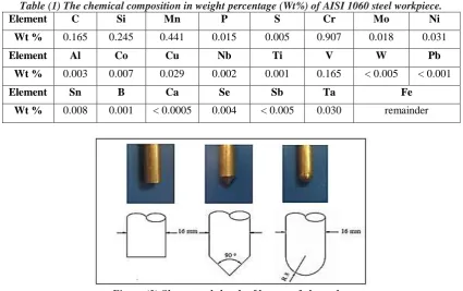
Table (1) The chemical composition in weight percentage (Wt%) of AISI 1060 steel workpiece.
Element C Si Mn P S Cr Mo Ni
Wt % 0.165 0.245 0.441 0.015 0.005 0.907 0.018 0.031
Element Al Co Cu Nb Ti V W Pb
Wt % 0.003 0.007 0.029 0.002 0.001 0.165 < 0.005 < 0.001
Element Sn B Ca Se Sb Ta Fe
Wt % 0.008 0.001 < 0.0005 0.004 < 0.005 0.030 remainder
Figure (3) Shapes and sketch of bottom of electrodes.
2. Selection of process parameters
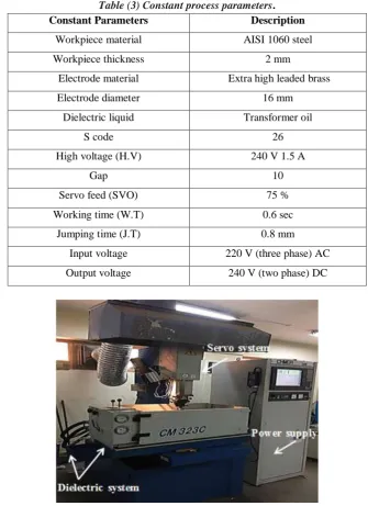
Three variable process parameters have been considered (electrode shape, current, and pulse duration with pulse interval), as shown in Table (2). The constant parameters of the process are shown in Table (3). Die Sinking EDM process was used to perform the experiments on a CHMER EDM machine of CM 323C model making a hole in the center of workpieces in the University of Technology, as shown in Figure (4).
Table (2) Variable process parameters.
Variable parameters Level 1 Level 2 Level 3
Electrode shape (E.S) flat conical round
Current (Ip) 10 A 20 A 42 A
Pulse duration (Ton)
Pulse interval (Toff)
25 µs 37 µs
50 µs 12 µs
[N.G. Ghazey* et al., 4(10): October, 2017]
ISSN: 234-5197
Impact Factor: 2.715
I
NTERNATIONAL
J
OURNAL
OF
R
ESEARCH
S
CIENCE
&
M
ANAGEMENT
Table (3) Constant process parameters.
Constant Parameters Description
Workpiece material AISI 1060 steel
Workpiece thickness 2 mm
Electrode material Extra high leaded brass
Electrode diameter 16 mm
Dielectric liquid Transformer oil
S code 26
High voltage (H.V) 240 V 1.5 A
Gap 10
Servo feed (SVO) 75 %
Working time (W.T) 0.6 sec
Jumping time (J.T) 0.8 mm
Input voltage 220 V (three phase) AC
Output voltage 240 V (two phase) DC
Figure (4) CHMER EDM machine components.
The weight of the electrode before and after the machining process was measured for each experiment by the sensitive balance Instrument and the machining time was recorded by CHMER EDM machine to calculate the EWR from the following equation:
EWR =EB−EA
MT×ρE (1) Where:
EWR: Electrode wear rate (mm3/min).
EB: Electrode weight before machining (g).
EA: Electrode weight after machining (g).
MT: Machining time (min).
[N.G. Ghazey* et al., 4(10): October, 2017]
ISSN: 234-5197
Impact Factor: 2.715
I
NTERNATIONAL
J
OURNAL
OF
R
ESEARCH
S
CIENCE
&
M
ANAGEMENT
Design of Experiments (DOE)
DOE was done to investigate the effects of input variables (factors) on output variable (response) at the same time for a series of runs, in which changes are made to the input variables, identify the process conditions that improve process quality, and determine the factor settings that optimize the results using Minitab statistical software (MSS). Factorial design was the selected design of MSS.
Full factorial design helps in improving the process through considering the important of process factors and to achieve the relative importance of each of these factors on response parameter. This method tries various combinations of factors settings to establish the best way to run the process [24]. It provides easier interface for specifying model terms, easier interface for calculating predicted values, and automatic model selection to identify important factors. General full factorial design type was used. It includes 2 to 15 factors each factor can have any number of levels (at least two levels but not more than 100 levels). 33 (level factor) full factorial design
was used producing 27 runs.
Results and discussion
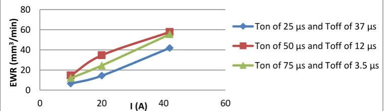
1. Flat Electrode ShapeFigure (5) shows the effect of current using values of (10, 20, 42 A) on EWR for various pulse duration and pulse interval levels using values of (25 µs with 37 µs, 50 µs with 12 µs, and 75 µs with 3.5 µs), respectively. It is obvious that as current increases, the EWR increases for all pulse duration and pulse interval levels. The increasing of EWR is due to increasing the diameter of crater in electrode surface that is caused by strong spark that make temperature higher.
Figure (5) Effect of current on EWR for various pulse duration and pulse interval levels using flat electrode.
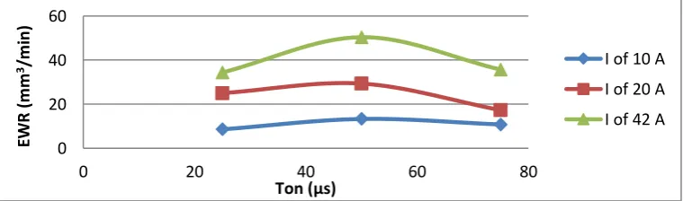
Figure (6) shows the effect of pulse duration using values of (25, 50, 75 µs) on EWR for various currents using values of (10, 20, 42 A). It is obvious that as pulse duration increases the EWR increases but after a specific value of pulse duration of 50 µs, it decreases for all currents. Reduction in EWR from longer pulse duration of 75 µs is due to erratic cutting that is caused by forming bridges on electrode surface by the particles of molten material.
Figure (6) Effect of pulse duration on EWR for various currents using flat electrode.
Figure (7) shows the effect of pulse interval using values of (3.5, 12, 37 µs) on EWR for various currents using values of (10, 20, 42 A). It is obvious that as pulse interval increases, the EWR increases but after a specific value of pulse interval of 12 µs, it decreases for all currents. Increasing the value of EWR is due to clean gap
0 20 40 60 80
0 20 40 60
EW
R
(m
m
3/m
in
)
I (A)
Ton of 25 µs and Toff of 37 µs
Ton of 50 µs and Toff of 12 µs
Ton of 75 µs and Toff of 3.5 µs
0 20 40 60 80
0 20 40 60 80
EW
R
(m
m
3/m
in
)
Ton (µs)
[N.G. Ghazey* et al., 4(10): October, 2017]
ISSN: 234-5197
Impact Factor: 2.715
I
NTERNATIONAL
J
OURNAL
OF
R
ESEARCH
S
CIENCE
&
M
ANAGEMENT
and decreasing after a specific value of pulse interval of 12 µs caused by arcing that creates by remaining debris on electrode surface.
Figure (7) Effect of pulse interval on EWR for various currents using flat electrode.
2. Conical Electrode Shape
Figure (8) shows the effect of current using values of (10, 20, 42 A) on EWR for various pulse duration and pulse interval levels using values of (25 µs with 37 µs, 50 µs with 12 µs, and 75 µs with 3.5 µs), respectively. It is obvious that as current increases, the EWR increases for all pulse duration and pulse interval levels. The increasing of EWR is due to high discharge energy that makes more positive ions collide with the surface of electrode which increases the amount of melted and vaporized material of electrode.
Figure (8) Effect of current on EWR for various pulse duration and pulse interval levels using conical electrode.
Figure (9) shows the effect of pulse duration using values of (25, 50, 75 µs) on EWR for various currents using values of (10, 20, 42 A). It is obvious that as pulse duration increases the EWR increases but after a specific value of pulse duration of 50 µs, it decreases for all currents. High pollution on electrode surface is the reason of reduction in EWR from longer pulse duration of 75 µs that reduces spark efficiency.
Figure (9) Effect of pulse duration on EWR for various currents using conical electrode.
Figure (10) shows the effect of pulse interval using values of (3.5, 12, 37 µs) on EWR for various currents using values of (10, 20, 42 A). Also, it is obvious that as pulse interval increases, the EWR increases but after a specific value of pulse interval of 12 µs, it decreases for all currents. Increasing the value of EWR is due to
0 20 40 60 80
0 10 20 30 40
EW
R
(m
m
3/m
in
)
Toff (µs)
I of 10 A I of 20 A I of 42 A
0 20 40 60
0 10 20 30 40 50
EW
R
(m
m
3/m
in
)
I (A)
Ton of 25 µs and Toff of 37 µs
Ton of 50 µs and Toff of 12 µs
Ton of 75 µs and Toff of 3.5 µs
0 20 40 60
0 20 40 60 80
EW
R
(m
m
3/m
in
)
Ton (µs)
I of 10 A
I of 20 A
[N.G. Ghazey* et al., 4(10): October, 2017]
ISSN: 234-5197
Impact Factor: 2.715
I
NTERNATIONAL
J
OURNAL
OF
R
ESEARCH
S
CIENCE
&
M
ANAGEMENT
better flushing of debris in the gap from electrode surface and decreasing after a specific value of pulse interval of 12 µs is due to the reason of arcing formation because of the remaining debris in the gap as a result of inability of the dielectric liquid to flush it away rightly.
Figure (10) Effect of pulse interval on EWR for various currents using conical electrode.
3. Round Electrode Shape
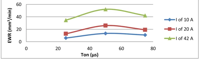
Figure (11) shows the effect of current using values of (10, 20, 42 A) on EWR for various pulse duration and pulse interval levels using values of (25 µs with 37 µs, 50 µs with 12 µs, and 75 µs with 3.5 µs), respectively. It is obvious that as current increases, the EWR increases for all pulse duration and pulse interval levels. The increasing of EWR is due to high current densities that rapidly heats the electrode and causes it to wear.
Figure (11) Effect of current on EWR for various pulse duration and pulse interval levels using round electrode.
Figure (12) shows the effect of pulse duration using values of (25, 50, 75 µs) on EWR for various currents using values of (10, 20, 42 A). It is obvious that as pulse duration increases the EWR increases but after a specific value of pulse duration of 50 µs, it decreases for all currents. At longer pulse duration of 75 µs a layer of carbon elements precipitates from the dielectric liquid on electrode surface and increases wear resistance producing reduction in EWR.
Figure (12) Effect of pulse duration on EWR for various currents using round electrode.
Figure (13) shows the effect of pulse interval using values of (3.5, 12, 37 µs) on EWR for various currents using values of (10, 20, 42 A). It is obvious that as pulse interval increases, the EWR increases but after a specific
0 20 40 60
0 10 20 30 40
EW
R
(m
m
3/m
in
)
Toff (µs)
I of 10 A
I of 20 A
I of 42 A
0 20 40 60
0 20 40 60
EW
R
(
m
m
3/m
in)
I (A)
Ton of 25 µs and Toff of 37 µs
Ton of 50 µs and Toff of 12 µs
Ton of 75 µs and Toff of 3.5 µs
0 20 40 60
0 20 40 60 80
EW
R
(m
m
3/m
in
)
Ton (µs)
I of 10 A
I of 20 A
[N.G. Ghazey* et al., 4(10): October, 2017]
ISSN: 234-5197
Impact Factor: 2.715
I
NTERNATIONAL
J
OURNAL
OF
R
ESEARCH
S
CIENCE
&
M
ANAGEMENT
value of pulse interval of 12 µs, it decreases for all current, as discussed for the Figures (7) and (10) for flat and conical electrodes, respectively.
Figure (13) Effect of pulse interval on EWR for various currents using round electrode.
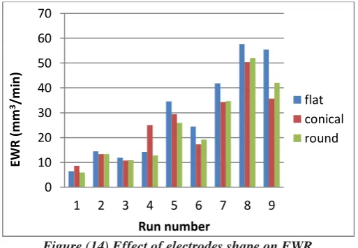
4. Effect of Electrode Shape on EWR
Figure (14) shows the experimented values of EWR for the nine runs for each electrode shape including flat, conical, and round. It is obvious that for most of runs conical electrode produces lowest EWR as compared to flat and round electrodes. The reason of this decreasing in conical electrode is due to lowest contact area between the conical electrode and workpiece. Including a point to be sparking area at first leads to low heat energy on surface of electrode and as electrode advances towards the workpiece, heat energy gradually increases at every instant. This gives intense heat on electrode surface causing melting and vaporizing by increased heat amount.
Figure (14) Effect of electrodes shape on EWR.
5. Prediction in Minitab Statistical Software (MSS)
The general full factorial design with confidence interval of 95% analyzes the experimented values by Minitab Software with general linear model.
A model is fitted for the data to generate residual plots to assess the importance of the effects such as normal probability plot between the residuals versus their expected values when the distribution is normal using regression and ANOVA. The output from analysis of variance (ANOVA) determines whether factors are significantly related to the response. Percentage contribution of each factor on EWR is measured from ANOVA table.
Conclusions
The main conclusions which can be deduced from the present study can be summarized as follows:
1. In flat electrode the maximum value of EWR is (57.696 mm3/min) and minimum value is (6.395
mm3/min).
0 20 40 60
0 10 20 30 40
EW
R
(m
m
3/m
in
)
Toff (µs)
I of 10 A
I of 20 A
I of 42 A
0 10 20 30 40 50 60 70
1 2 3 4 5 6 7 8 9
EW
R
(m
m
3/m
in
)
Run number
[N.G. Ghazey* et al., 4(10): October, 2017]
ISSN: 234-5197
Impact Factor: 2.715
I
NTERNATIONAL
J
OURNAL
OF
R
ESEARCH
S
CIENCE
&
M
ANAGEMENT
2. In conical electrode the maximum value of EWR is (50.413 mm3/min) and minimum value is (8.566
mm3/min).
3. In round electrode the maximum value of EWR is (52.109 mm3/min) and minimum value is (5.945
mm3/min).
4. From experimented results, it is found that for most of runs conical electrode gives lowest EWR due to lower contact area including in a point then increased region at every instant between the conical electrode and workpiece as compared to flat and round electrodes.
Acknowledgements
I would like to express my sincere gratitude and appreciation to my supervisor (Dr. Shukry Hammed Aghdeab), Department of Production Engineering and Metallurgy, Training and Workshops Center / Turning Unit in the University of Technology, and the Central Organization for Standardization and Quality Control.
References
[1] S. Dewangan and C.K. Biswas, "Experimental Investigation of Machining Parameters for EDM Using U-Shaped Electrode of AISI P20 Tool Steel", International Conference on Emerging Trends in Mechanical Engineering (ICETME), National Institute of Technology, Rourkela, India, 2011.
[2] E. C. Jameson, "Book: Electrical Discharge Machining", Society of Manufacturing Engineers (SME), Michigan, Dearborn City, pp.1, 2001.
[3] J. Kozak and K.P Rajurkar., "Hybrid machining processes, Evaluation and development", Proceedings of 2nd International Conference on Machining and measurement of sculptured surfaces, Krakow, pp. 501-536, 2001.
[4] "Book: non-conventional machining", Module 9, lesson 39, Second Edition, The Indian Institute of Technology Kharagpur (IIT Kharagpur).
[5] K. Roger, "Pdf: Sinker electrode material selection", EDM Today Publication, United States, 2008. [6] F.L. Amorim and W.L. Weingaertner, "The behavior of graphite and copper electrodes on the finish
die-Sinking electrical discharge machining (EDM) of AISI P20 tool Steel", Journal of the Brazilian Society of Mechanical Sciences and Engineering , Vol. 29, pp. 366-371, 2007.
[7] B.H. Yan, C.C. Wang, W.D. Liu, and F.Y. Huang, " Machining characteristics of Al2O3/6061Al
composite using rotary EDM with a disk like electrode", The International Journal of Advanced Manufacturing Technology, Vol. 16, pp. 322–333, 2000.
[8] J.S. Soni and G. Chakraverti, "Machining characteristics of titanium with rotary electro-discharge Machining", Elsevier Sequoia Library, Vol. 171, pp. 51–58, 1994.
[9] K.S. Don, "Book: Electro discharge machining", Fu Wen Publisher, Kaoxiong City, Taiwan, p. 40, 1994.
[10]G. Kucukturk and C. Cogun, "A New Method for Machining of Electrically Nonconductive Workpieces Using Electric Discharge Machining Technique", International Journal of Machining Science and Technology, Vol. 14, pp. 189–207, 2010.
[11]J.L Lin and C.L. Lin, "The use of the orthogonal array with grey relational analysis to optimize the electrical discharge machining process with multiple performance characteristics", International Journal of Machine Tools and Manufacture, Vol. 42, pp. 237-244, 2002.
[12]K.H. Ho and S.T. Newman, "State of the art electrical discharge machining (EDM)", International Journal of Machine Tools and Manufacture, Vol. 43, pp. 1287–1300, 2003.
[13]J.C. Hung, J.K. Lin, B.H. Yan, H.S. Liu and P.H. Ho, "Using a Helical Micro-Tool in Micro-EDM Combined with Ultrasonic Vibration for Micro-Hole Machining", Journal of Micromechanics and Microengineering, Vol. 16, pp. 2705–2713, 2006.
[14]A. A. Khan, M.Y.Ali and M. M. Haque, "A Study of Electrode Shape Configuration on The Performance of Die Sinking EDM", International Journal of Mechanical and Materials Engineering, Vol. 4, pp. 19 -23, 2009.
[N.G. Ghazey* et al., 4(10): October, 2017]
ISSN: 234-5197
Impact Factor: 2.715
I
NTERNATIONAL
J
OURNAL
OF
R
ESEARCH
S
CIENCE
&
M
ANAGEMENT
[16]G. D’Urso, M. Longo, G. Maccarini, and C. Ravasio, "Electrical Discharge Machining of Micro Holes on Titanium Sheets: Effect of Process Parameters and Electrode Shape", Department of Design and Technology, University of Bergamo, Italy, DOI: 10.3850/978-981-07-0319-6_211, January 2011. [17]A.Singh, P. Kumar and I.Singh, "Electric Discharge Drilling of Metal Matrix Composites with
Different Tool Geometries", Journal of Engineering Manufacture, Vol. 227, pp. 1245–1249, 2013. [18]S. H. Najem and M. A.Tawfiq, "Optimization of Electrode Wear Rate on Electrical Discharge
Machining AISI 304 SS with Multi Hole Electrode", International Journal of Mechanical Engineering and Technology (IJMET), Vol. 5, pp. 113-124, 2014.
[19]M. Manohar, T. Selvaraj , D. Sivakumar, S. Gopinath, and K. M. George, "Experimental Study to Assess The Effect of Electrode Bottom Profiles While Machining Inconel 718 Through EDM Process", Journal of Procedia Materials Science, Vol. 6, pp. 92–104, 2014.
[20]D.N. Mishra , A. Bhatia , and V. Rana, "Study on Electro Discharge Machining (EDM)", The International Journal of Engineering and Science (IJES), Vol. 3, pp. 24-35, 2014.
[21]R.S. Parmar, "Book: Manufacturing Processes and Automation", Khanna Publisher, First Edition, pp. 502-505, 2009.
[22]B. Singh, C.D. Singh, and J. Singh, "Improving the Process Capabilities of EDM: A Review", International Journal of Emerging Technologies in Computational and Applied Sciences (IJETCAS), Vol. 12, pp. 115-119, 2015.
[23]A. Descoeudres, "Characterization of Electrical Discharge machining Plasmas", Thesis, Federal Institute of Technology, Switzerland , Lausanne City, 125 pages, 2006.
![Figure (1) Working principle of EDM [(a) 23, (b) 22].](https://thumb-us.123doks.com/thumbv2/123dok_us/8460154.1708156/3.595.132.466.382.539/figure-working-principle-edm-b.webp)