Thermal Analysis on Mono-Block Type Divertor Based on
Subcooled Flow Boiling Critical Heat Flux Data against
Inlet Subcooling in Short Vertical Tube
Koichi HATA, Masahiro SHIOTSU
1)and Nobuaki NODA
2)Institute of Advanced Energy, Kyoto University, Uji 611-0011, Japan
1)Deptartment of Energy Science and Technology, Kyoto University, Uji 611-0011, Japan 2)National Institute for Fusion Science, Toki 509-5292, Japan
(Received 8 December 2005/Accepted 14 February 2006)
The subcooled flow boiling critical heat fluxes (CHFs) and the heat transfer coefficients (HTCs) data for the tube length,L, of 49, 99 and 149 mm with 9-mm inner diameter were applied to thermal analysis on the Mono-block type divertor of LHD. Incident CHFs for the divertor with the cooling tube diameter,d, of 10 mm and the carbon armor outer diameter,D, of 26 and 33 mm were numerically analyzed based on the measured CHFs and HTCs at the inlet pressure of around 800 kPa. The numerical solutions were also compared with those for the Flat-plate type divertor, which were numerically analyzed for the divertor with the cooling tube diameter
d=10 mm and the divertor width,w, ranging from 16 to 30 mm. It is confirmed that the ratio of the one-side heating CHF data, qcr,inc, to the uniform heating CHF data, qcr,sub, can be represented as the simple equation
based on the numerical solutions. The values of theqcr,incforL=50, 100 and 150 mm were estimated with various
D/dandw/dat higher pressures. c
2006 The Japan Society of Plasma Science and Nuclear Fusion Research
Keywords: subcooled flow boiling critical heat flux, incident critical heat flux, mono-block type divertor, numerical solution
DOI: 10.1585/pfr.1.017
1. Introduction
The understanding of the critical heat flux (CHF) on vertical tube inner surface in subcooled water flowing up-ward is important as a database for the design of a divertor plate in a nuclear fusion facility.
Various studies have been conducted on the CHF in water for high heat flux heat removal. For example, the ex-perimental investigation for CHF on tubes with and with-out a twisted tape or a coiled wire has been presented. Heat transfer coefficient and critical heat flux for water in swirl flow through tubes with internal twisted tapes was conducted by Gambillet al. [1]. The correlation of the non-boiling heat transfer coefficient was presented and it was demonstrated that CHF with swirl flow was twice as large as with straight flow through an identical tube with-out a twisted tape. The swirl tube with the effect of two-phase heat transfer and asymmetric heating of tubular ele-ments was numerically analyzed to study the performance of swirl-flow-based neutral particle beam targets by Milora
et al. [2]. CHF of subcooled flow boiling with water in tubes under peripherally non-uniform heating conditions was investigated by Nariai and Inasaka [3]. Divavinet al.[4] carried out the high heat flux experiments on rectan-gular samples with cylindrical cooling ducts with one-side heating to the effect of a porous coating deposed on inner
author’s e-mail: [email protected]
cooled surface on the Incident Critical Heat Flux (ICHF) performance at water subcooled boiling regime. They de-fined the empirical correlation between ICHF at one-side heating condition and geometrical parameters of elements of cooling design. The critical heat flux (CHF) exper-iments for the different geometries (smooth tube, finned swirl tube, screw tube and hypervapotron) were performed in the thermal hydraulic conditions of fusion reactors: one-side heating, high heat flux and water-cooled by JAERI (Japan Atomic Energy Research Institute) [5]. Recently, three-dimensional thermal measurements for a one-side-heated mono-block were made for the robust design of one-side-heated plasma-facing components and other high heat flux components by Boydet al. [6].
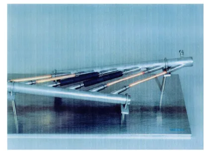
The heat load tests have been under way by the elec-tron beam heating on a divertor element which consists of the carbon armors joined to the copper heat-sink with a cooling tube. A helical type fusion experimental device which is Large Helical Device (LHD) located in the Na-tional Institute for Fusion Science, Japan, has two types of divertor element. One is Mono-block type (Cylindri-cal one), the other is Flat-plate type (Rectangular one). Figure 1 shows a typical photograph of the LHD diver-tor, Mono-block type. It is important to clarify the rela-tion between the uniform heating CHF data,qcr,sub, on the
test tube heated by a steadily increasing current and the
c
Fig. 1 Typical photograph of the LHD divertor, Mono-block type.
one-side heating CHF data,qcr,inc, on the divertor element
heated by an electron beam facility with the effect of the cooling tube length.
The purpose of this study is first to make the ther-mal analysis of the Mono-block type divertor based on the CHFs and the HTCs data for the tube length,L, of 49, 99 and 149 mm with 9-mm inner diameter, and secondly to give the ratio of theqcr,incto the qcr,suband establish the
database for the high heat flux thermal management at the divertor.
2. Divertor Types
The cross-sectional views of Mono-block type diver-tor and Flat-plate type are shown in Figs. 2 (a) and (b), respectively. The Mono-block type divertor is made of the oxygen-free copper cooling tube with 10 mm inner diameter and 1.5 mm thickness, and the carbon armor (CX2002U) with 33 mm outer diameter and 10 mm thick-ness. The cooling tube is located in the center of the car-bon armor. The carcar-bon armor is brazed to the cooling tube. On the other hand, the Flat-plate type one is made of the oxygen-free copper block of 30 mm wide by 25 mm high and the carbon tile (CX2002U) of 30 mm wide by 10 mm high. The carbon tile is brazed to the copper block. The cooling tube with the inner diameter of 10 mm is horizon-tally located at the height of 17 mm from the lower surface on the central line of the copper block. The heated lengths of the divertors are given as 49, 99 and 149 mm in this
Fig. 2 Cross-sectional views of LHD divertors, (a) Mono-block type and (b) Flat-plate type.
right, left and lower surfaces for the Flat-plate type one are under the adiabatic conditions because the divertor is equipped in the plasma vessel which will be normally op-erated under ultra-high vacuum (10−5Pa for hydrogen).
3. Numerical Analysis of the
Mono-Block Type Divertor
3.1
Fundamental equations
The unsteady two-dimensional heat conduction equa-tion for the Mono-block type divertor in the coordinate sys-tem shown in Fig. 3 is described as follows. The Flat-plate type one is shown in Appendix.
∂
∂t(ρcT)=
1
r
∂ ∂r
rλ∂∂T r
+1
r
∂ ∂θ
λ
r
∂T
∂θ
ford/2≤r≤D/2 and 0≤θ≤π, (1) whereρ,candλare density (kg/m3), specific heat (J/kg
K) and thermal conductivity (W/mK), respectively and the carbon armor outer diameter, D, and the cooling tube di-ameter,d, are in (m). Thez-direction thickness of the con-trol volume is assumed to be unity. The numerical analysis is performed within 0 ≤θ ≤ πas the symmetrical prob-lem. The boundary conditions are expressed in the follow-ing forms.
∂T
∂r =0 atr=D/2 for 0≤θ≤π/2, (2)
(qwall)i=qinc
18 π
sin π 18i−sin
π 18(i−1)
atr=D/2 forπ(i−1)/18≤θ≤πi/18(i=10 to 18),
(3)
q=−qθ atr=d/2, (4)
Fig. 3 Coordinates of Mono-block type divertor.
where the outer surface heat flux of carbon armor, (qwall)i, and the inner surface heat flux of the cooling tube,qθ, are in (W/m2). The (q
wall)iare given as the values calculated from the incident heat flux,qinc, at everyπ/18 forθranging
fromπ/2 toπ. Theqθare given with the aid of the relation between the heat flux,q, and the surface temperature,Ts,
previously obtained based on the surface temperature of the cooling tube numerically analyzed at everyπ/18 forθ ranging from 0 toπ.
3.2
Calculation method
Boiling curves measured by three different heated lengths of the test tubes under the same experimental con-dition (pressure at inlet of heated section, Pin, in (kPa),
flow velocity, u, in (m/s) and inlet liquid temperature, Tin, in (K) =constant) are used for the numerical
anal-ysis. Figure 4 shows the heat transfer characteristics for
d=9 mm tube with L=149 mm for the inlet condition of
Pin=775 kPa,u=9.9 m/s andTin=306.76 K as a typical
ex-ample. The heat flux gradually becomes higher with an increase in (Ts−Tin) on the forced convection heat
trans-fer derived from Nusselt correlation [17] up to the point where the slope begins to increase with heat flux following the onset of nucleate boiling, and increases up to a value called CHF where the heater surface temperature rapidly jumps from the nucleate boiling heat transfer regime (N-B) to the film boiling one (F-(N-B). The film boiling curve in the figure is given by the values derived from Shiotsu and Hama’s correlation [18, 19]. It is assumed that the film boiling exists for the heater surface temperature,Ts,
higher than the homogeneous spontaneous nucleation tem-perature,TH. The transition boiling curve is given as the
straight line drawn between the point for (Ts−Tin) 20 K
higher than that at CHF and that at the minimum heat flux. The plateau was adopted based on the experimental study
Fig. 4 Relationship betweenqand (Ts−Tin) with L=149 mm at
on transient boiling heat transfer including transition to film boiling on a heated horizontal cylinder in a pool of water caused by a rapid pressure reduction from an ini-tial pressure [20, 21]. Minimum film boiling temperature or heat flux on inner surface of a vertical tube with wa-ter flowing upward is neither clearly understood at present experimentally nor theoretically. On the other hand, Saku-raiet al. [22] performed systematic experiments of mini-mum film boiling states on horizontal cylinders in a pool of liquids at various pressures. They observed that the min-imum film boiling temperature, Tmin, in each liquid was
lower than the homogeneous spontaneous nucleation tem-perature,TH, at atmospheric pressure, and it increased and
approachedTHwith the increase in the pressure. In case of
water,Tminalmost agreed withTHfor the pressures higher
than around 1 MPa. They also reported that the minimum film boiling state seemed to be characterized by the surface temperature rather than the heat flux. It was becauseTmin
on different diameter cylinders under the same condition agreed with each other, although the heat flux at the point was lower for larger diameter cylinder due to the depen-dence of film boiling heat transfer coefficients on cylinder diameter. It is assumed based on these facts thatTmin for
the forced convection film boiling of water at high pres-sures would be aroundTH.
The qθ value for each control volume is given from the boiling curve shown in Fig. 4 as the heat flux at the surface temperature numerically obtained for each control volume. The boiling curve shown in Fig. 4 was formulated to give the surface heat flux on the cooling tube in the CFD (Computational Fluid Dynamics) code as follows:
q=C∆Tn, (5)
∆T =Ts−Tin, (6)
where all constants,C andn, are given in Table 1. The surface heat flux,qθ, and the surface temperature, Ts, on
Table 1 Constants of Eq. (5)
the cooling tube was calculated from the analyzed temper-ature,T1, at the central point of the first control volume on
the cooling tube, by the 50-times iteration on the thermal conduction in the control volume as follows:
λcu(T1)= f(T1), (7)
qs1=C(T1−Tin)n, (8)
Ts=T1−qs1
ln(1+ ∆r/d) 2πλcu(T1)
, (9)
qs=C(Ts−Tin)n, (10)
Ts=T1−qs
ln(1+ ∆r/d) 2πλcu(T1)
, (11)
qθ=qs, (12)
where the thermal conductivity of the oxygen-free copper, λcuis in (W/mK) and the depth of the first control volume
on the cooling tube,∆r, is in (m). Equations (10) and (11) were iterated 50 times in the code. All the calculations were made by using the PHOENICS code [23].
4. Results and Discussion
4.1
Conditions for calculation
The heat characteristic of Mono-block type divertors are numerically analyzed under the following conditions:
Mono-block Type Divertors
Material : Oxygen free copper tube and cylindrical CX2002U
Outer diameter (D) : 26 and 33 mm Heated Length (L) : 49, 99 and 149 mm Incident Heat Flux (qinc) : 11–16 MW/m2
Cooling Tube Diameter (d) : 10 mm Cooling Water
Inlet Pressure (Pin) : 775–792 kPa
Flow Velocity (u) : 9.9 m/s
Inlet Liquid Temperature (Tin) : 306.76–308.65 K
(33.61–35.5◦C)
4.2
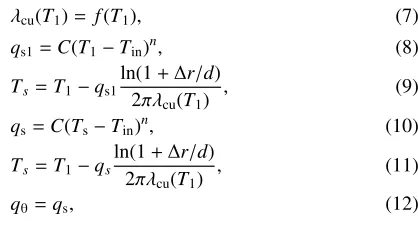
Incident critical heat flux
Figure 5 shows the numerically obtained time varia-tions in the surface temperature of the carbon armor on the central line of the divertor,Twall, the inner temperature of
the carbon armor,Tcx, the outer temperature of the copper
cooling tube,Tcu, and the inner surface temperature of the
copper cooling tube,Ts, forqinc=11 MW/m2for the carbon
armor outer diameter,D, of 33 mm with the cooling tube diameter,d, of 10 mm, which is cooled with highly sub-cooled and pressurized water for the inlet liquid tempera-ture,Tin, of 306.76 K at the inlet pressure,Pin, of 775 kPa
with the flow velocity,u, of 9.9 m/s. The surface
tempera-ture of the carbon armor (CX2002U) rapidly increases up to 1199 K within 5 seconds of the heating and gradually approaches the constant value of about 1218 K with the elapse of time.
The peripheral distributions of the surface heat flux,
qθ, and the inner surface temperature,Ts, on the cooling
sur-Fig. 5 Time variations in Twall, TCX, TCu and Ts for
qinc=11 MW/m2withL=149 mm.
Fig. 6 Peripheral distribution ofqwall,qθ,Ts,TCu,Ts−TinandTwall
forqinc=11 MW/m2.
face after 12 seconds of the heating are shown in Fig. 6 with the experimental data point of CHF,qcr,sub. The line,
θ=0◦, is the central axis of the carbon armor. Theqθvalues
on the cooling tube are widely distributed ranging from 4.86 MW/m2 atθ=0◦ (the bottom of the cooling tube) to
18.95 MW/m2 at θ=180◦ (the top of the one) which is
almost the CHF value. It is assumed the vapor behav-ior on the cooling tube surface from this figure that the heat transfer on the inner surface of the cooling tube for
qinc=11 MW/m2 will be in non-boiling forced convection
for the lower part of the tube and in nucleate boiling (N-B) for the upper part of the tube.
The numerical solutions of the time variations inTwall,
Tcx, Tcu andTs forqinc=12 MW/m2 are shown in Fig. 7.
After 3.4 seconds of the heating, theTwallvalue steeply
in-creases again because the top inner surface of the cooling tube begins to be covered with vapor, the vapor spreads downward the cooling tube surface and the surface tem-perature of the cooling tube jumps to that of the film boil-ing regime (F-B). The incident critical heat flux,qcr,inc, is
Fig. 7 Time variations in Twall, TCX, TCu and Ts for
qinc=12 MW/m2withL=149 mm.
defined as the maximum value ofqincwithout the steep
in-crease ofTwalldue to the surface temperature on the
cool-ing tube increascool-ing to that of the film boilcool-ing regime (F-B). The contours of the cross-section temperature of the divertor which were numerically solved at 12 and 8 sec-onds after the heating forqinc of 11 and 12 MW/m2 are
shown on Fig. 8. The phenomena on the inner surface of the cooling tube are observed to be in the non-boiling forced convection and nucleate boiling regimes (N-B), and the film boiling regime (F-B), respectively.
4.3
Influence of heated length
The numerical solutions ofqincfor the heated length,
L, of 49, 99 and 149 mm are shown in Fig. 9 with the cir-cle, triangle and rectangle symbols. Theqincvalues with
and without the transition to film boiling are shown as the solid and open symbols, respectively. Theqcr,incvalue is
around 14 MW/m2 at theL/d of 4.9. They become lower
with an increase in theL/dand finally arrive at the value of about 12 MW/m2atL/dof 14.9. Theq
cr,incvalue becomes
14.3% lower with an increase inL/dfrom 4.9 to 14.9. The critical heat fluxes, qcr,sub, for uniformly heated tube are
also shown in this figure for comparison. Furthermore, the values calculated from the CHF correlation against inlet subcooling mentioned below, Eq. (13), are shown as a bro-ken line. Theqcr,subdata are in good agreement with this
correlation. Theqcr,incvalues show nearly the same trend
of dependence ofqonL/dasqcr,sub, although they are
al-most 38% lower than the latter. Based on these data un-der the subcooled condition, it is supposed that the liquid subcooling and the bubble boundary layer on the heated surface become little by little lower and thicker along the heated length of the test tube at the same inlet liquid sub-cooling,∆Tsub,in, condition for the wideL/drange.
Fig. 8 Contour of cross-section temperature.
Fig. 9 Relationship betweenqincandL/dforD/d=3.3.
based on the effects of L/d clarified in the CHF experi-ment [12, 13, 16].
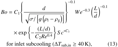
Bo=C1
σ/gdρl−ρg
−0.1
We−0.3
L
d
−0.1
×exp
− (L/d)
C2Re0.4
S c∗C3
for inlet subcooling (∆Tsub,in≥40 K), (13)
whereC1=0.082, C2=0.53 and C3=0.7 for L/d≤around
40, andC1=0.092,C2=0.85 andC3=0.9 forL/d>around
40.Bo,Re,S c∗andWeare boiling number, (=qcr/(Ghfg)),
Reynolds number, (=Gd/µl), non-dimensional
in-let subcooling, (=cpl∆Tsub,in/hfg) and Weber number,
(=G2d/(ρ
lσ)), respectively. Saturated thermo-physical
properties were evaluated at the outlet pressure.
This correlation can describe not only these CHF data for Pin of around 800 kPa but also the authors’
published CHFs data (1805 points) for the wide ranges of Pin=159 kPa to 1 MPa, d=2 to 12 mm, L=21.5 to
149.7 mm, ∆Tsub,in=10 to 151 K and u=4.0 to 13.3 m/s
within 15% difference for 40 K≤∆Tsub,in≤151 K.
4.4
Influence of carbon armor thickness
The divertor for the outer diameter,D, of 26 mm is nu-merically analyzed to clarify the influence of the thickness on the incident critical heat flux. The numerical solutions ofqinc withL=49, 99 and 149 mm are shown in Fig. 10
with the circle, triangle and rectangle symbols, respec-tively. The numerical solutions ofqinc forD=33 mm are
also plotted in this figure for comparison. Theqcr,incvalue
forL=149 mm as a typical example is around 12 MW/m2
at the D/d of 3.3. They become larger with a decrease in theD/d and arrive at the value of about 13 MW/m2 at
D/d of 2.6. Theqcr,inc value becomes 8.3% larger with a
decrease in D/d from 3.3 to 2.6. It is supposed that the incident critical heat flux becomes higher for smallerD/d
value because the heat induced by collecting on the car-bon armor upper surface with the outer diameter,D, and transfering to the cooling tube with 10 mm inner diame-ter becomes smaller for smallerD/dvalue under the same incident heat flux condition.
4.5
Influence of divertor shape
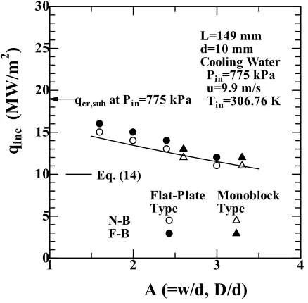
Figure 11 shows the influence of the divertor shape on the incident critical heat flux. The numerical solutions of
qincfor the Mono-block type divertor withL=149 mm are
plotted on theqincvs.D/dgraph as open and solid
trian-gles. Those for the Flat-plate type one are shown versus w/d as open and solid circles in this figure for compari-son [9, 10]. Theqcr,incvalue for the Flat-plate type one is
around 16 MW/m2 at thew/dof 1.6. They become lower
Fig. 10 Relationship betweenqinc and D/d for L=49, 99 and 149 mm.
Fig. 11 Relationship between qinc and A(=D/d, w/d) for the Mono-block type and Flat-plate type divertors.
of about 12 MW/m2atw/dof 3. Theq
cr,incvalues become
almost 4 MW/m2 lower with an increase in thew/d from
1.6 to 3. Theseqcr,incvalues for the Mono-block type and
Flat-plate type divertors are approximately expressed by the single curve on this figure with no influence of the di-vertor shape on the incident critical heat flux.
4.6
Comparison with uniform heating data
The ratios of the calculated qinc for the Mono-block
type divertor and the Flat-plate type one with the cool-ing tube diameter of 10 mm at the pressures of 594 kPa to 1 MPa to the experimental data ofqcr,subwith the SUS304
Fig. 12 Relationship betweenqinc/qcr,sub and A(=D/d, w/d) for
the Mono-block type and Flat-plate type divertors.
tube of 9 mm inner diameter at the same pressure condi-tion,qinc/qcr,sub, are shown vsA(=D/dorw/d) in Fig. 12.
The calculated values of theqcr,incfor the heated length of
49 to 149 mm with the flow velocity of 6.9 to 13.3 m/s at the inlet pressure of 594 kPa to 1 MPa are approximately expressed by the following correlation:
qcr,inc
qcr,sub =
0.97e−A/6.4, (14)
whereA=D/d for Mono-block type divertor and A=w/d
for Flat-plate type one.
The curve derived from this correlation is independent of the divertor shape, the flow velocity and the inlet pres-sure for the entire calculated range. On the other hand, theqcr,subvalue in Eq. (14) for∆Tsub,in higher than around
40 K is given by Eq. (13). Theqcr,incvalue for higher
pres-sures can be predicted by using Eqs. (13) and (14). The
qcr,incvalue thus derived for the inlet pressures of 0.5, 1 and
2 MPa at the flow velocity of 10 m/s with the inlet liquid temperature of 308.15 K are shown in Fig. 13 as a curve for each value of the pressure. Theqcr,incvalue forL=50 mm
becomes higher than 20 MW/m2with the decrease in the
A smaller than 2 for the pressure of 2 MPa. Those for
L=100 and 150 mm becomes higher than 15 MW/m2with the decrease in theAsmaller than 3.3 and 2.6 for the pres-sure of 2 MPa, respectively.
It is considered that the incident critical heat flux,
qcr,inc, for the divertor will be larger than the value derived
Fig. 13 Relationship between qcr,inc and A(=D/d, w/d) at Pin=0.5, 1 and 2 MPa.
5. Conclusions
The subcooled flow boiling critical heat fluxes (CHFs) and the heat transfer coefficients (HTCs) forL=49, 99 and
149 mm with 9-mm inner diameter were applied to thermal analysis of the Mono-block type divertor of LHD. Incident CHFs,qcr,inc, for the divertor with the cooling tube
diame-ter,d, of 10 mm and the carbon armor outer diameter,D, of 26 and 33 mm were numerically analyzed.
The qcr,inc values become 14.3% lower with an
in-crease inL/dfrom 4.9 to 14.9. They show nearly the same trend of dependence ofqcr,subon L/d, although they are
almost 38% lower than the values ofqcr,sub.
The qcr,inc values become almost 8.3% larger with a
decrease inD/dfrom 3.3 to 2.6.
Theqcr,incvalues were also compared with those for
the Flat-plate type divertor with the cooling tube diameter
d=10 mm and the divertor width, w, ranging from 16 to
30 mm. Theseqcr,incvalues for the Mono-block type and
Flat-plate type divertors are approximately expressed by the single curve with no influence of the divertor shape on the incident critical heat flux.
The ratio of the one-side heating CHF data,qcr,inc, to
the uniform heating CHF data,qcr,sub, can be represented
as the simple equation based on the numerical solutions. The values of theqcr,incfor the tube lengths of 50, 100
and 150 mm were estimated with variousD/dandw/dat higher pressures.
Acknowledgments
This research was performed as a LHD joint research project of NIFS (National Institute for Fusion Science), Japan, L2-22, 2001–2003 and was partially supported by the Japan Society for the Promotion of Science, Grant in Aid for Scientific Research (C), 15560180, 2003 and 2004.
Appendix
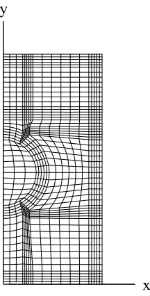
A.1 Numerical analysis of the Flat-plate type divertor
The unsteady two dimensional heat conduction equa-tion in boundary fitted coordinate as shown in Fig. A1 is described as follows:
∂
∂t(ρcT)=
∂ ∂x
λ∂T ∂x
+∂y∂
λ∂T ∂y
for 0≤x≤w/2,0≤y≤0.035. (A1) The numerical solution is performed within 0≤x≤w/2 as
the symmetrical problem. The boundary conditions are ex-pressed in the following forms:
∂T
∂x =0 atx=0, (A2)
∂T
∂x =0 atx=w/2, (A3)
∂T
∂y =0 aty=0, (A4)
q=qinc aty=0.035, (A5)
q=−qθ atx=
d2
4 −(y−0.017)
2, (A6)
where the divertor width,w, and the cooling tube diameter,
d, are in (m) and the incident heat flux,qinc, and the surface
heat flux,qθ, of the cooling tube are in (W/m2). All calcu-lations were made by using the PHOENICS code [23].
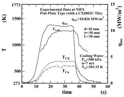
A.2 Comparisons of our numerical solution with other worker’s experimental data
The mock-up experiment has been performed by Kubota et al. [24, 25] at the National Institute for Fu-sion Science (NIFS). This is the high heat flux heat re-moval experiment on the mock-up divertor plate heated by electron beam facility. The cross-sectional view of this divertor-plate is shown in Fig. A2. The hatched area on the upper surface of the divertor shown in figure is
x
y
heated with the heat flux of 11.6 MW/m2. The
inci-dent heat flux,qinc, within the heated length is equivalent
to 10.826 MW/m2. The cooling water for P
in=500 kPa,
u=7 m/s and Tin=303.15 K is circulated through the
di-vertor. The mock-up experimental results of time varia-tions are shown in Fig. A3. The Twallis measured by a
pyro-meter, andTCX and TCu by thermocouples. These
experimental data are numerically analyzed by the CFD code developed in this work. Figure A4 shows the nu-merically obtained time variations in the surface temper-ature,Twall, the inner temperature of the carbon tile,Tcx,
and the inner temperature of the copper block, Tcu, for
qinc =10.8 MW/m2with the divertor of 30 mm wide and
the cooling tube diameter,d, of 10 mm, which is cooled with highly subcooled and pressurized water for the inlet liquid temperature,Tin, of 306.55 K at the inlet pressure,
Pin, of 594 kPa with the flow velocity,u, of 6.9 m/s. The
Fig. A2 Flat-plate type divertor used by the heat load test (Kub-otaet al. [24, 25]).
Fig. A3 Time variations in Twall, TCX and TCu for qinc=10.8
MW/m2in the heat load test (Kubotaet al.[24, 25]).
experimental data in Fig. A3 are also shown in the figure for comparison. From the comparison of the numerical re-sults with the mock-up rere-sults, theTwall,TCXandTCu in
the numerical results and those in the mock-up results at maximum values are approximately same, respectively, al-though their increasing rates for the experiment are a little smaller than those for the numerical solution. This fact ver-ified that numerical analyses are reliable. It is assumed that the incident heat flux of the mock-up experiment might be just below the maximum incident heat flux.
Figure A5 shows the comparison between Divavin et al.’s one-side-heating CHF data [4] without porous coating for d=6 mm, w=13 mm, L=60 mm, ∆Tsub,out=160 K and
Pin=2 MPa. These incident critical heat flux,qcr,inc, are
nu-merically solved by the CFD code developed in this work. And theqcr,incvalues are also predicted by the CHF
corre-lation against inlet subcooling, Eq. (13), theqcr,inc
correla-tion, Eq. (14) and the energy balance equation for the test
Fig. A4 Comparison of Kubota et al. data with the numerical solution.
tube given as
∆Tsub,out=Tsat,out−(Tout)cal=Tsat,out−
Tin+
4Lqcr,sub
ucplρld
,
(A7) where∆Tsub,out,Tsat,out and (Tout)cal are outlet liquid
sub-cooling (K), outlet saturation temperature (K) and cal-culated outlet liquid temperature (K). Thermo-physical properties were evaluated at the temperature of {Tin +
(Tout)cal}/2. The average values of their experimental data
show nearly same trends of dependence on u. And fur-thermore, those are also within 25% of the values obtained from the values calculated from Eqs. (13), (14) and (A7) and the numerical solutions.
[1] W.R. Gambill, R.D. Bundy and R.W. Wansbrough, Chem. Eng. Prog. Symp. Series57, 127 (1961).
[2] S.L. Milora, S.K. Combs and C.A. Foster, Nucl. Eng. Des./Fusion3, 301 (1986).
[3] H. Nariai, A. Ishikawa and F. Inasaka,Proc. NURETH-6, (1993) p. 715.
[4] V.A. Divavin, S.A. Grigoriev and V.N. Tanchuk, Proc. ASME Heat Transfer Division,HTD-Vol. 317-1, IMECE (1995) pp. 143–148.
[5] J. Boscary, M. Araki and M. Akiba, JAERI-Research 97-053(Japan Atomic Energy Research Institute, 1997). [6] R.D. Boyd, A. Ekhlassi, P. Cofie and H. Zhang, Int. J. Heat
Mass Transf.47, 2183 (2004).
[7] K. Hata, K. Fukuda, M. Shiotsu, A. Sakurai, N. Noda, O. Motojima and A. Iiyoshi,Proc. 6th International Confer-ence on Nuclear Engineering, ICONE-6362 (1998) pp. 1– 16.
[8] K. Hata, K. Fukuda, M. Shiotsu and A. Sakurai,9th Int. Topical Meeting on Nuclear Reactor Thermal Hydraulics
(1999) pp. 1–20.
[9] G. Sato, K. Hata, M. Shiotsu and N. Noda,Proc. 8th Int.
Conference on Nuclear Engineering, ICONE-8126 (2000) pp.1–12.
[10] K. Hata, T. Sato and M. Shiotsu,Proc. 9th Int. Conference on Nuclear Engineering, ICONE-9569 (2001) pp. 1–12. [11] K. Hata, T. Sato, T. Tanimoto, M. Shiotsu and N.
Noda,Proc. 10th Int. Conference on Nuclear Engineering, ICONE10-22324 (2002) pp. 1–10.
[12] K. Hata, T. Tanimoto, H. Komori, M. Shiotsu and N. Noda,Proc. 11th Int. Conference on Nuclear Engineering, ICONE11-36116 (2003) pp. 1–10.
[13] K. Hata, H. Komori, M. Shiotsu and N. Noda,Proc. 10th Int. Topical Meeting on Nuclear Reactor Thermal Hy-draulics, NURETH10-C00207 (2003) pp. 1–13.
[14] K. Hata, H. Komori, M. Shiotsu and N. Noda,Proc. 12th Int. Conference on Nuclear Engineering, ICONE12-49194 (2004) pp. 1–10.
[15] K. Hata, M. Shiotsu and N. Noda, J. Heat Transf., Trans. ASME, Series C,126, 312 (2004).
[16] K. Hata, H. Komori, M. Shiotsu and N. Noda, JSME Inter-national Journal, SeriesB,47, 306 (2004).
[17] W. Nusselt, Forsch. Geb. Ingenieurwes.2, 309 (1931). [18] M. Shiotsu and K. Hama,Proc. NURETH-8, Vol.2(1997)
pp. 679–690.
[19] M. Shiotsu and K. Hama, Nuc. Eng. Des.200, 23 (2000). [20] A. Sakurai, M. Shiotsu and K. Hata,Heat and Fluid Flow
in Water Reactor Safety, C199/77, (The Institute of Me-chanical Engineers, London, 1977) pp.55–62.
[21] A. Sakurai, M. Shiotsu and K. Hata, Multiphase Trans-port, Fundamentals, Reactor Safety, Applications, Vol. II, (Hemisphere Pub. Corp., Washington D.C., 1980), pp.727– 747.
[22] A. Sakurai, M. Shiotsu and K. Hata, Experimental Thermal and Fluid Science3, 450 (1990).
[23] D.B. Spalding,The PHOENICS Beginner’s Guide(CHAM,
UK, 1991).
[24] Y. Kubota, N. Noda, A. Sagara, A. Komori, N. Inoue, K. Akaishi, H. Suzuki, N. Ohyabu and O. Motojima, Proc. ASME Heat Transfer Division, HTD-Vol.317-1, IMECE (1995) pp.159–163.