WIRELESS DIGITAL STETHOSCOPE
USING BLUETOOTH TECHNOLGY
GODFREY A. MILLS
Department of Computer Engineering, University of Ghana, P. O. Box LG 25, Legon, Accra, Ghana
[email protected] http://<www.ug.edu.gh>
THOMAS A. NKETIA
Department of Biomedical Engineering, University of Ghana, P. O. Box LG 25, Legon, Accra, Ghana
[email protected] http://<www.ug.edu.gh>
ISAAC A. OPPONG
Department of Biomedical Engineering, University of Ghana, P. O. Box LG 25, Legon, Accra, Ghana
[email protected] http://<www.ug.edu.gh>
ELSIE EFFAH KAUFMANN
Department of Biomedical Engineering, University of Ghana, P. O. Box LG 25, Legon, Accra, Ghana
[email protected] http://<www.ug.edu.gh>
Abstract
Stethoscopes are used to listen to acoustic signals from the internal organs of the human body. Although stethoscopes play a very important role in the diagnosis process, the chest piece and the connecting cable are known to facilitate transmission of pathogens from patient to patient and from patient to the user. Replacing the connecting cable with a wireless system may help reduce the potential risk and further allow broadcasting of the signals to multi-users for examination. This work reports on the design of a two-piece Bluetooth-based wireless system that eliminates the connecting cables in electronic stethoscopes. The design consists of a Bluetooth based integrated chest-piece module for captured acoustic sound transmission and a microcontroller-based (MSP430) head-piece receiver module for decoding the data for the three operational modes of the stethoscope. The design was first tested using a chirp signal source with frequency of 10 Hz – 5 kHz. Results obtained for the three operational frequency bands of the stethoscope were consistent with the expected behaviour of the stethoscope. Keywords: Bluetooth, Microcontroller, FIR filter, Stethoscope, Auscultation
1. Introduction
Stethoscopes are used regularly by medical personnel to listen to acoustic signals picked from the internal parts of the human body during diagnosis and treatment of patients. Typically, signals that are picked from the body for diagnosis include that of the heart, lungs, and bowels [1]. Although stethoscopes have become ubiquitous in healthcare delivery and are often used as a symbol of medicine in several media, their use may also serve as a threat to both patient and health personnel. For example, the diaphragm of the chest-piece and the connecting cable of the stethoscopes have been shown to harbor potentially pathogenic bacteria as these elements make the most contact with the patients and are also the parts mostly exposed to hospital wares [2].
signal captured from a patient can be broadcast to multiple users of the device within operational range with restricted access.
In this work, we focus on the design reconfiguration and development of the electronic stethoscope by introducing wireless transmission between the chest-piece and the head-piece using the Bluetooth technology and a low-power microcontroller (MSP430) to facilitate the operational mode selection. The advantage of using the Bluetooth protocol is its ability to allow very high data rates compared to other protocols such as the Zigbee and Wi-fi. The proposed design aims to enable different users in a team to select different examination modes from the broadcast data without interference, minimize the mobility issues during examinations, and also reduce some of the inherent problems associated with connecting cable of the modern electronic stethoscope.
2. System design description
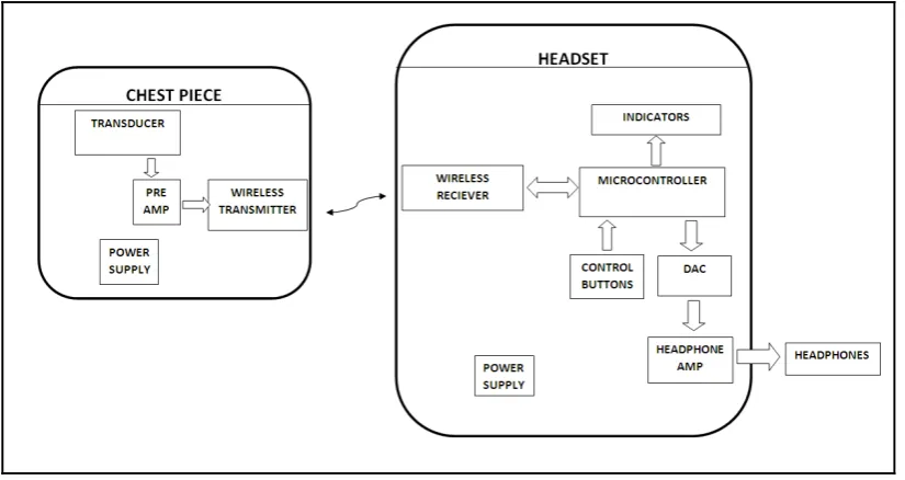
A typical stethoscope is made up of three components: the head-piece, chest-piece, and a connecting cable that serves as a communication link between the two main components. The chest-piece embodies the acoustic or electronic sensor which captures the analog signals or sounds from the body and transmits the data in the form of voltage signals over the communication link to the head-piece. The proposed wireless stethoscope design consists of two modules: an integrated chest-piece that serves as the transmitting system and integrated head-piece that serves as a receiver system. The chest-head-piece system consists of the data acquisition interface that is integrated with the wireless module whereas the head-piece system consists of an integrated wireless receiver unit and a microcontroller. Figure 1 shows the hardware architectural view of the wireless stethoscope system and sub-systems interconnection and Figure 2 shows the conceptual view of the expected device.
Figure 2: Diagram of the form factor of the proposed wireless stethoscope
2.1. Design of integrated chest-piece system
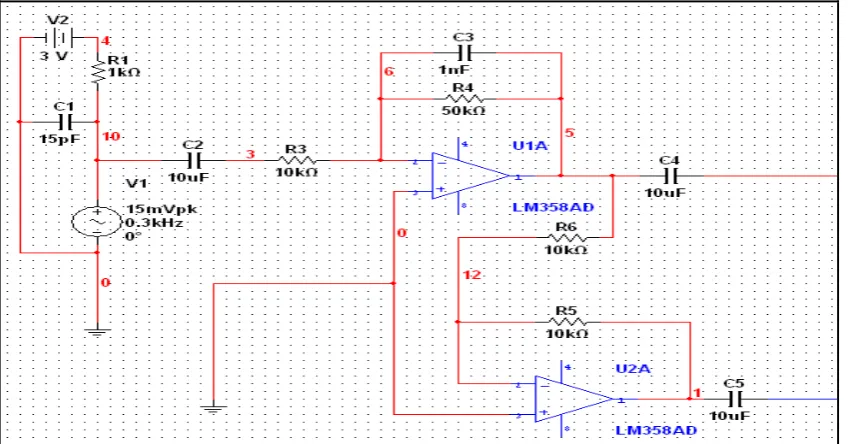
The chest-piece captures the analog signals or sounds from the human body by means of an electret condenser microphone as a transducer. The captured electrical signal is amplified using an analog amplifier circuit before encoding for transmission via the transmitter. Figure 3 shows the microphone biasing and amplification circuit in the chest-piece. The circuit was designed using Multisim design suite of National Instruments. The electret microphone was designed to have a biasing voltage of 2 V for the operation of the incorporated field effect transistor, which is consistent with the conventional electret microphones. With a power supply, V2 of 3.0 V, resistor R1 of 1.0 kΩ and internal resistance, Rs, of the electret microphone (2.2 kΩ based on manufacturer datasheet) the required bias voltage was obtained. An active low pass anti-aliasing filter with a cut-off frequency, fc of 3 kHz and a gain of 25.5 dB was found adequate to ensure that the sampling theorem was
obeyed. To minimize attenuation effect at low frequency, de-coupling and DC noise rejection capacitors (C2, C4, C5) shown in the circuit in Figure 3 were chosen to be sufficiently high (10 µF). The second stage amplifier circuit, U2A, was employed to produce an inverted output signal with unity gain. The output together with its inversion served as a differential input to the wireless transmitter circuit. This ensured that the output is less susceptible to interference as the difference remains the same despite voltage spikes in both lines.
In equation (1), do is a reference point which was set at 0.2 m beyond which the path loss becomes relevant, λ is
the wavelength of the wireless signal, γ is the path loss exponent, d is the distance in meters measured beyond do
and Po is the shadow fading effect. To find the acceptable signal power required for transmission in order to
receive a healthy signal at the receiver for 2.5 GHz wireless signal, the following parameters were used; γ = 4, d
= 10m, and P0 = 10 dB. From these, a power loss PL of 102 dB was obtained. Based on the data transfer rate and
transmission range of this design (data rate of 192 kbps from the sampling rate and number of bits; and distance of less than 10 m), a Class 2 Version 2.0+ EDR device was considered most appropriate.
2.3. Design of integrated receiver head-piece system
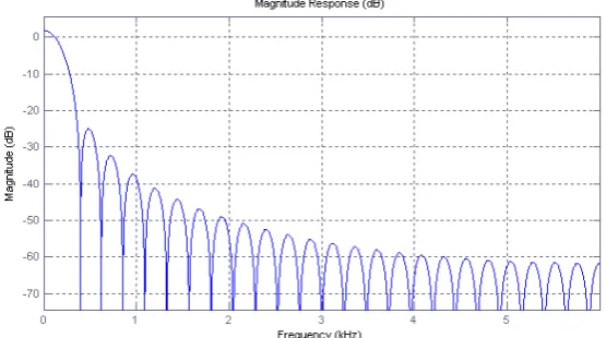
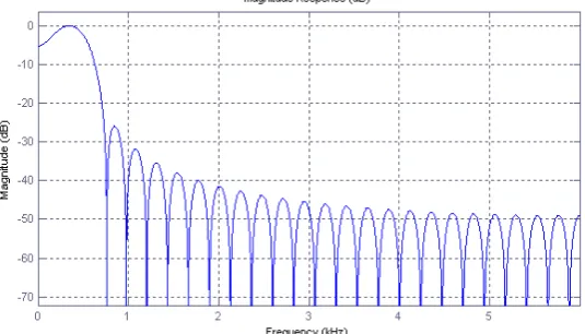
The design for the microcontroller-based receiver head-piece system included a wireless receiver unit, a digital signal processor, control buttons, LED indicators, amplifier circuit, and power supply source as illustrated in Figure 1 above. The signal processor which is a microcontroller (MSP430) performs filtering operation on the received wireless signal. Three operational modes were developed to conform to the stethoscope applications: Bell mode (20 - 220 Hz), Diaphragm mode (50 - 600 Hz), and Extended mode (20 - 2000 Hz). These frequency bands define the characteristic frequency spectra that apply to the various applications. For example, heart sounds are usually of low frequency and therefore, fall within the Bell mode band. To facilitate the selection process, three buttons to change the operational modes and three LEDs were provided, one for each mode to provide feedback to the user. Figures 4(a) to 4(c) show the magnitude responses of the filter for the bell, diaphragm, and the extended operational modes, respectively.
Figure 4 (b) Filter Magnitude Response for Diaphragm mode
Figure 4 (c) Filter Magnitude Response for the Extended mode
With the filter design, the finite impulse response (FIR) filter structure was used as against the infinite impulse response (IIR) filter due to the guaranteed stability and easy constraint to linear phase offered by the FIR. The Matlab Filter Design and Analysis (FDA) toolbox was used to design the filters as windowed Gaussian FIR filters. Based on the expected characteristics of the input signal, the following parameters were found to give acceptable results for the different operational modes: filter roll-off characteristic parameter α = 0.6, filter order, N = 50, and signal sampling rate, Fs =12 kHz. The filter coefficients and the transfer functions were derived which served as the platform for encoding on the microprocessor.
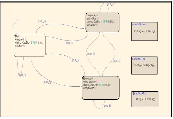
Figure 5: Finite State Machine Stateflow Model of the behaviour of the microcontroller
Once a mode has been selected for the signal through the microprocessor process and filtered to produce the desired signal, the output was in turn converted for analog display. A double-stage amplifier circuit was designed for that purpose. The circuit first amplifies the output signal obtained from the microcontroller before passing it to the headphone. A variable resistor in the circuit allows the user to vary the extent of amplification (volume control). Figure 6 shows the receiver head-piece system amplification circuit model. The first stage of the circuit performed anti-aliasing filtering operation for the signal reconstruction. The analog amplifier circuits were modeled and designed using the Multisim design suite.
Figure 6: Receiver Headset amplification circuit
2.4. Numerical simulation and system integration
This chirp signal was found to be consistent with a signal characteristic from a condenser microphone captured on an oscilloscope.
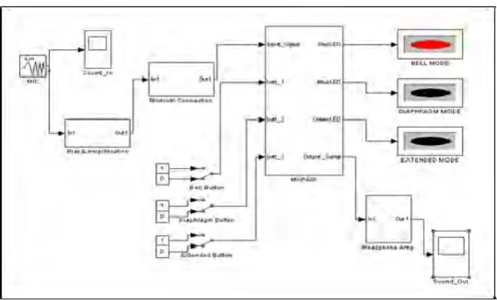
Figure 7: Simulink model of the wireless stethoscope system
3. Results and discussion
To ascertain the performance of the proposed wireless stethoscope design, a numerical model of the system was first created in Simulink environment. Parameters used in the test model were: 14dB amplifier gain for the chest-piece circuit, variable (volume control) gain of 25.5 dB to 30 dB for the head-piece circuit, MSP430 microcontroller, and chirp waveform with frequency range of 10 Hz – 5 kHz as input source. Figure 8(a) shows the characteristics of the unidirectional input chirp waveform used for the testing and Figure 8(b) is the resulting output waveform for the three operational modes of the stethoscope: bell mode, diaphragm mode, and the extended mode, obtained from the simulation model. Modes were selected based on the type of examination required by the user using the microcontroller. Following the choice of a desired mode, all the frequencies outside that mode were filtered out. As shown in Figure 8(b), signal attenuation within the pass-band range appeared minimal whereas attenuation within the stop-band range is sufficiently high. This ensures that the output signal within any mode adheres strictly to the filter specifications.
software. The code was run independently on the MSP430 microcontroller which delivered desired results. The numerical model produced expected results and aspects of the system deployment in hardware show promising results. To validate these results, the complete prototype is currently under construction. This will be reported in further studies. Much as the proposed wireless stethoscope has great potential, it may also come with some challenges such as privacy of patient’s data and security challenges if proper encryption protocols are not properly addressed. Another challenge may come from protocol configuration to ensure that signals from one wireless stethoscope device do not leak to or interfere with other wireless stethoscopes within the surroundings of examinations. A possible remedial action for the latter challenge may be taken by ensuring that each wireless device is first uniquely configured to a number of headset units before deployment to respond only to the transmitter to which it is configured.
4. Conclusions
In this paper, a novel design idea of integrating wireless bluetooth technology into a two-piece electronic stethoscope has been presented. Bluetooth protocol is known for its effectiveness in short range peer-to-peer communication and can therefore offer short range high efficiency data transfer in a simple device. To demonstrate the operational capability of the proposed device, a numerical model of the system was created. Results showed that it is possible for wireless data to be broadcast to multi head-piece sets and the various operational modes selected for evaluation with the aid of a microcontroller. Preliminary implementation of aspects of the system in hardware produced results that show that it is possible to realize the wireless electronic stethoscope in hardware and commercialized. A full two-piece wireless electronic stethoscope will eliminate the connecting cables of the conventional stethoscope and offer easy movement of the device users around patients during auscultation, minimize the spread of infections, and contribute to teamwork, especially in auscultation training of healthcare practitioners, where data is broadcast simultaneously to the members in the team for evaluation. Hardware implementation of a prototype system is currently ongoing using donated development boards from Texas Instruments Inc.
Acknowledgments
The authors would like to express their profound gratitude to the Texas Instruments Inc., (Ben Sarpong and Tuli Dake) for their initiative for the supply of the MSP430 microcontroller boards as well as the Bluetooth wireless development boards for implementation of the proposed wireless stethoscope project.
References
[1] Saladin K. S. (2003). Anatomy and Physiology: The Unity of Form and Function, 3rd Ed., McGraw-Hill, New York.
[2] Marinella M. A, Pierson C, Chenoweth C. (1997): The stethoscope: a potential source of nosocomial infection. Arch Intern Med; 157, pp. 786-790.
[3] 3MTM Littmann (April 20 2012): Electronic Stethoscope Model 3200 with Bluetooth Technology.
http://www.mystethoscope.com/littmann-3200-electronic-stethoscope-bluetooth-p-429.html
[4] 3M Littmann (April 20 2012): Electronic Stethoscope Model 4100WS with Ambient Noise Reduction. http://www.mansionhealthselect.com/Littmann-Electronic-Stethoscope-p/4100ws.htm
[5] Texas Instruments (April 20 2012): Digital Stethoscope Solution. http://www.element14.com/community/docs/DOC-39206/l/texas-instrumentsdigital-stethoscope-implementation-on-tms320c5515-dsp-medical-development-kit-rev-a
[6] Thinklab (April 20 2012): ds32a Digital Electronic Stethoscope. http://www.thinklabsmedical.com/
[10] Jatupaiboon N., Pan-ngum S., Israsena P. (2010): Electronic stethoscope prototype with adaptive noise cancellation. 8th International Conference on ICT and Knowledge Engineering, pp: 32 – 36.
[11] Hung, K, Zhang, Y. T. (2002): Usage of Bluetooth in wireless sensors for tele-health. 24th Annual Conference of Biomedical
Engineering Society, 23-26 October, 2002
[12] Ying-Wen Bai and Chao-Lin Lu. (2005): Embedded digital stethoscope using adaptive noise cancellation filter and type I Chebyshev IIR bandpass filter to reduce noise of the heart sound. Proceedings of 7th International Workshop on Enterprise Networking and Computing in Healthcare Industry, pp. 278-281
[13] Yang Tang, Guitao Cao, Hao Li. (2010): The Design of Electronic Heart sound Stethoscope based on Bluetooth. 4th International
Conference on Bioinformatics and Biomedical Engineering, pp. 1 - 4.
[14] Chan Chien Jia-REn, Cheng-Chi Tsi. (2004): The Implementation of a Bluetooth-based Wireless Phonocardio-diagnosis system. International Conference on Networking, Sensing and Control.
[15] Pereira D., Hedayioglu F. (2011): DigiScope – Unobtrusive Collection and Annotating of Auscultations in Real Hospital Environment. 33rd International Conference of the IEEE EMBS, pp. 1193-1196
[16] Sa-Ngasoongsong A., Bukkapatnam, S. T. S (2010): Wireless Transmission of Sensor Signals for Phonocardiology Applications. IEEE Sensors 2010 Conference, pp. 1975-1978