T o m a s O l s s o n 9 Modris Megnis 9 Janis Varna H e n r i k L i n d b e r g
Study of the transverse liquid flow paths in pine and spruce using scanning
electron microscopy
Received: October 4, 1999 / Accepted: August 1, 2000
Abstract Samples of pine
(Pinus sylvestris)
and spruce(Picea abies)
were impregnated with a low-viscous epoxy resin using a vacuum process. The epoxy was cured in situ and the specimens sectioned. Deposits of the cured epoxy was then observed in the wood cavities using a scanning electron microscope. The investigation concentrated on tracing the transverse movements of a viscous liquid in the wood, and special attention was therefore given to the cross-field area between ray cells and longitudinal tracheids. A damage hypothesis is proposed based on the results obtained in the present investigation in combination with those from earlier studies on linseed oil-impregnated pine: In addition to the morphology of the bordered pits, viscous liquid flow in wood is dependent on damage that occurs during the impregnation procedure. For pine sapwood, liquid flow is enabled through disrupted window pit mem- branes, which divide the longitudinal tracheids and the ray parenchyma cells. A mechanism accounting for the reduced permeability of pine heartwood is believed to be deposits of higher-molecular-weight substances (extractives) in the ray parenchyma cells and on the cell walls. In spruce the thicker ray cells in combination with the smaller pits, which are connected to the longitudinal tracheids, reduce permeabil- ity considerably.Key words Impregnation 9 Microstructure 9 Liquid flow path- Microscopy
T. Olsson ([]) . H. Lindberg
Division of Wood Material Science, Lulefi University of Technology, Skelleftegt 931 87, Sweden
Tel. +46-910-585337; Fax: +46-910-585399 e-mail: [email protected]
M. Megnis. J. Varna
Division of Polymer Engineering, Lule~ University of Technology, Skellefte~ 931 87, Sweden
Introduction
Wood is a material used in many building and construction applications. Unfortunately, wood degrades biologically if certain conditions (e.g., the supply of water, oxygen, and nourishment and a suitable temperature range) are met. 1 Impregnation of wood has been used successfully for many years as a method to extend the life in service for wood products.
One of the most important aspects of wood as far as impregnation is concerned is related to its porosity and how internal cavities at the microscopic level communicate with each other. Although much effort has been put into trying to understand liquid flow in wood, and more importantly the critical factors that limit liquid flow in wood, many questions remain unanswered. Variations in the morphol- ogy of the interconnecting pits within and among species add to the complexity of being able to predict reliably the success of a particular preservative treatment. The ease by which liquids flow in conifers is often related to the struc- ture of the bordered pit membranes, with the aspiration process 2 usually stated to be the most significant obstacle to capillary flow. 3-5 Variability of aspiration within annual rings is also reported to cause higher uptake in latewood than in earlywood. 6-s
Some studies have suggested that rays act as important flow paths for liquids during impregnation. 9'1~ However, theories concerning spreading from ray elements to longitudinal tracheids (or vice versa) are still disputed. Some authors have shown that the ray parenchyma in pine can act as important flow paths, 9"11-1s whereas others state the opposite, z4 For softwoods, the ray tracheids, situ- ated at the outermost tunnels in a ray, are often found to serve as an important liquid transport path during impregnation. ~5,~6
The objective of this work was to determine qualitatively the microstructural features that promote viscous liquid movements in pine
(Pinus sylvestris)
and spruce(Picea
abies).
More specifically, the work focused on understand- ing the role of the rays in liquid uptake.Materials and methods
Sample collection and impregnation
Specimens were taken from defective free pine and spruce, with an initial moisture content of 12%. The specimens were obtained from both sapwood and heartwood and grouped accordingly. The tangential and radial dimensions of the samples were both 20mm and the longitudinal di- mension 30mm. The annual rings were oriented parallel to one side of the specimen, selected so the annual ring widths were of the same magnitude within each group. The trans- verse cut ends were sealed with a layer of silicone rubber to prevent exaggerated flow.
Impregnation with a low-viscous (20mPas) epoxy was carried out by placing the samples in a desiccator submerged in the epoxy and applying a vacuum of approxi- mately 3 • 10 2kPa for 5min. The vacuum was then re- leased and the specimens returned to atmospheric pressure, allowing the penetrant to flow into the cavities. The impreg- nated specimens remained immersed in the liquid and were then cured in an oven at 60~ for 24h. This procedure was expected to leave the epoxy "frozen" in the cavities in the penetrated state. The technique minimizes the risk of the penetrant to recede when the pressure is released.
To evaluate the overall retention of epoxy following im- pregnation, the density of the samples was measured before and after this process. Small samples (weighing about 6 g) from each batch of impregnated specimens were immersed in mercury and weighed to an accuracy of 0.001 g.
Sectioning and microscopy
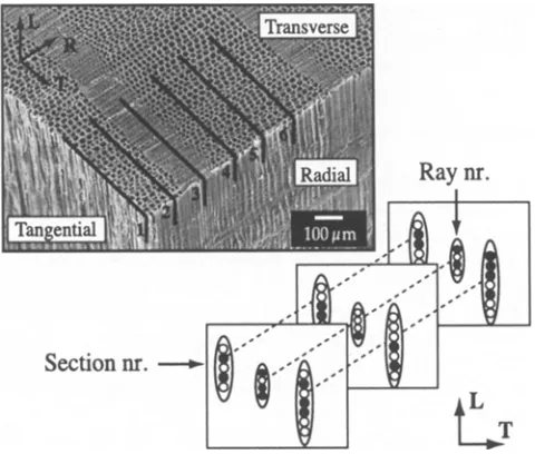
To evaluate the penetrant flow paths and particularly the extent to which the rays were followed, the longitudinal/ tangential (LT) and longitudinal/radial (LR) planes were studied by sectioning. The method is illustrated in Fig. 1, which also shows the three main planes in wood: transverse, radial, tangential. Sequential sections, exemplified by num- bers 1-6 in Fig. 1, were taken from each sample using a Reichert sliding microtome with steel blades. The thickness of the individual sections (S) was about 180~um, with the first section located 3 m m from the radial surface. In this way, any flow characteristics specifically related to the edge of the sample were avoided. Ten sequential sections were analyzed for pine and six for spruce. The observed area in each section was 0.4 • 0.6mm (L • T), covering a total of 16-20 individual rays (R).
Using this method, serial observations were made of the same rays from the LT plane, as illustrated in the right-hand portion of Fig. 1. In Fig. 1, a filled circle shows the presence
Fig. 1. Sequential sectioning. L, longitudinal; T, tangential
Table 1. Macroscopic weight increase
Specimen Weight increase (%)
Pine
Sapwood 45
Heartwood 24
Spruce
Sapwood 8
Heartwood 6
of epoxy in the ray elements. A total 574 ray fractions were studied (~ S • R), which covered several thousand indi- vidual ray elements.
To study the L R plane, cracks were introduced to split the specimens along the rays, creating one visible surface from each side of the crack, which allowed the path and extent of penetration of the impregnant to be followed. All specimens were sputter-coated with platinum in a Denton Desk II sputter before being observed in a Jeol 5200 scan- ning electron microscope.
Results and discussion
The average weight increase of the specimens following impregnation is given in Table 1. The overall level of im- pregnation achieved using the vacuum technique described earlier was small compared to the maximum theoretical level. The weight increase resulting from filling all porosi- ties would be more than 100% for dry wood with a density of 500kg/m 3. As is usual with impregnation, however, the specimens exhibited a gradient from the surface into the specimen that resulted in higher concentration near the surface than the average values presented in Table 1.
smaller: In spruce sapwood it was around one-sixth that for pine. The weight increase difference between spruce sap- wood and heartwood is far smaller than that for pine.
Sequential sectioning of the LT plane
The results obtained from studying the sequential tangen- tial sections are shown in Fig. 2. The vertical axis shows the area fraction of ray voids filled with epoxy for each group of specimens (represented by the horizontal axis). The total numbers of sections and rays are presented in the lower part of Fig. 2. As the tangential and radial planes were unsealed, rays were considered to be important for dispersion of the penetrant (epoxy). In the remainder of this article the con- nection between the rays and longitudinal tracheids are referred to as cross-field pits.
It can be seen in Fig. 2 that the rays in pine sapwood become almost completely filled with the penetrant. The fractional area occupied by the epoxy in the ray tracheids is
Fig. 2. Fractional retention of epoxy in the rays. S, R, sections, rays
0.9. The high degree of filling (0.85) observed in the ray parenchyma in the pine samples is contradictory to an earlier study, ~4 which concluded that the ray parenchymas were impermeable to liquids. For pine heartwood the corresponding numbers are significantly lower: 0.15 and 0.20 respectively. For spruce, the fractional retention is considerably lower in both sapwood and heartwood.
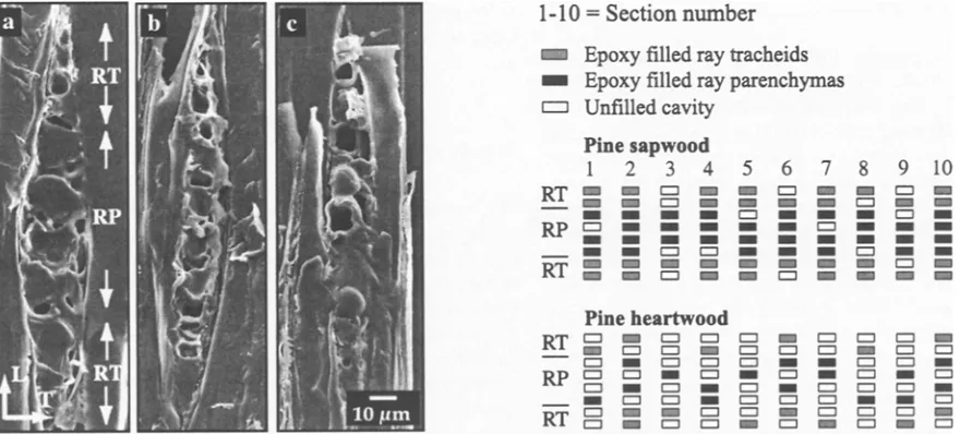
Three sections through one ray from pine sapwood viewed from the LT plane are shown at the left of Fig. 3. The cells at the upper and lower end are ray tracheids (RTs) and the middle cells are ray parenchymal cells (RPs). In Fig. 3a, both the RTs and the RPs are homogeneously filled with polymer. In the other micrographs not all the RTs/RPs are filled, and the pattern of filling varies. In Fig. 3b empty RPs and RTs are spread over the whole ray, whereas in Fig. 3c the empty RPs/RTs are predominantly located in the upper part. By observing sections of the same ray, it is possible to determine whether the epoxy depositions are continuous throughout a given row of ray cells.
The results obtained for pine sapwood and heartwood are summarized on the right in Fig. 3. Numbers 1-10 refer to the observed sections. Again, RTs are located at the upper and lower extremes of the ray. Depositions of epoxy are marked when present in the RTs or RPs. The right-hand portion of Fig. 3 is for a single ray, and the filling pattern in other rays may well be slightly different.
For pine sapwood, the filling appeared to be continuous throughout the sectioned area. However, this should not be taken to imply that the flow during impregnation proceeds radially through the rays. This point is discussed later.
For heartwood, the filling pattern of the epoxy is more scattered, with the epoxy distributed more unevenly. The same scattered distribution was observed in both the sap- wood and heartwood of spruce. By studying the LT sections from both pine and spruce, no certain conclusion can be drawn whether the ray parenchyma or the ray tracheids
play a dominant role in macroscopic uptake of epoxy. How- ever, the results obtained for the pine heartwood and spruce show that these materials have a tess permeable ray struc- ture. As a consequence, the flow may have to change chan- nels, which requires more energy (pressure) owing to the much smaller openings around obstacles in the flow direc- tion. The heterogeneous distribution of the penetrant may support theories 20 claiming that entrapped air blocks the flow path. Another possibility is that an impermeable cell wall structure or higher-molecular-weight resins (extrac- tives) block the ray cells.
Analysis of the L R plane
A more continous analysis of the rays can be achieved by studying split radial surfaces along the ray (i.e., in the LR plane) and reveal the relative importance of the ray ele- ments (RT and RP) in the transverse flow path. Figure 4 shows a split ray from pine sapwood obtained approxi- mately 4 m m from the penetrating surface. Parts of one annual ring, earlywood to latewood, can be seen in at mark- ers a-e. The area covers five rows of RP cells and two rows (one on each side) of R T cells. It is clear that the polymer has filled most of the longitudinal tracheids in the observed area and that the regions near the RP cells are heavily filled with epoxy (Fig. 4,1). The tracheid marked b is unfilled, and it can be seen that the cross-field pits belonging to this tracheid have remained intact. Evidence of flow through pits in the ray tracheids is found in the lower part of Fig. 4, marked by 2.
A closer view of another cross-field pit area is presented in Fig. 5, which shows longitudinal tracheids (a-e) and the connections to a ray, which is located underneath. The tra-
cheids marked a and b are unfilled, whereas the tracheids marked c-e contain varying amounts of epoxy. The upper- most window pit m e m b r a n e in tracheid c is intact, whereas the middle (1) and right pits apparently provide a path for flow through the distorted window pit membranes. The cross-field pit between ray tracheids and longitudinal trac- heids are marked by 2. No evidence of transverse flow from ray tracheids is found in this micrograph.
The mechanism of distorted cross-field pits in pine (Pinus sylvestris) providing lateral flow paths has been pro- posed by other researchers, ~3 who suggested that the divid- ing m e m b r a n e is damaged at some critical level of pressure. Findings from the present study indicate that even if the applied pressure gradient is relatively low (approximately
Fig. 5. Longitudinal/radial (LR) plane in pine sapwood showing the effect of flow through distorted window pit membranes. See text for other explanations
130 kPa) the cross-field pits in pine sapwood could still serve as important flow paths.
The morphology of unimpregnated and impregnated pine sapwood has been investigated. 21 Observations of fracture surfaces by scanning electron microscopy (SEM) revealed evidence of microstructural changes (damage) caused by the impregnation process. The damage observed was a combination of distorted pit membranes and micro cracks in the cell wall material and was closely correlated with the specific amount of uptake (filling). The damage resulting from impregnation at high uptake levels, in turn, caused the mechanical properties of the impregnated wood material to be reduced. 22
The sharp density transition between earlywood and latewood must be regarded as a mechanically weak zone. Interestingly, deposits of the penetrant in the L R plane were commonly found in regions near density gradients related to annual ring borders. This point is illustrated in Fig. 6, which shows an area where the radial penetrating front is directed from earlywood (a) to the sharp transition between earlywood and latewood (c). The tracheid marked b is heavily filled with the penetrant. In addition, the cross- field pits near this tracheid are filled with epoxy, showing the tangential spreading through distorted window pit membranes in the ray parenchyma (white arrows). The physical significance of this effect has been investigated using fractographic methods, 22 which indicate that the inter- face between earlywood and latewood is almost certainly weakened during pressure impregnation treatment.
The lower permeability of pine heartwood is most often claimed to be attributed to a high degree of aspiration of the bordered pitsY Incrustation of the bordered pit membranes add to the resistance to flow. A view of the cross-field pits recorded from pine heartwood is presented in Fig. 7, which shows a typical appearance with localized penetration of epoxy (black arrows) that has most likely entered the parenchymatous ray cell from the longitudinal tracheid underneath. The transverse liquid flow is apparently more restricted through the large cross-field pits in the heartwood compared to sapwood. This may also be observed as a scat-
tered distribution in the ray and the deposits switching between ray elements in the sequential sections (Fig. 3).
The transformation from sapwood to heartwood causes changes in the parenchymatous cells. Polyphenols are laid down in the window pits (cross-field pits) and in the walls of ray p a r e n c h y m a ] 4'25 We believe that this restricts transverse flow from longitudinal tracheids passing through the large cross-field pits in ray parenchyma of pine. Hence, this is also suggested as the main mechanism responsible for the re- duced permeability of pine heartwood.
The superior treatability of pine compared to spruce has earlier been attributed to the larger volumetric amount of ray tracheids. 15 Furthermore, the pits between the ray trac- heids and longitudinal tracheids in pine are claimed to re- main unaspirated to a greater extent than in spruce. 15 The ray tracheids of pine sapwood were in fact seen to be filled to a great extent in this study. Still, we argue that the rela- tive importance of the ray parenchyma as providing a trans- verse flow path is of greater importance than ray tracheids. The characteristics of ray cells in pine and spruce were investigated earlier. 26 The mean size of the m e m b r a n e divid- ing ray parenchyma cells and longitudinal tracheids was found to be 12 • 31,um in pine but only 2/~m (in diameter) for the corresponding pit in spruce. The tangential cell wall thickness of the parenchymatous cells was also investigated and was found to average 0.5#m and 4 # m for pine and spruce, respectively. If the internal wood microstructure, pit membranes (as shown in Figs. 4-6), or cell wall material is damaged as a consequence of an general impregnation pro- cess, the thin cross-field pits in pine sapwood would serve as a more efficient flow path for the liquids (i.e., because the liquid flow is proportional to the fourth power of the capil- lary radius - Poiseille's law).
In the present investigation the volume fraction of epoxy found in the ray elements of spruce was low (approximately 5%). The differences between sapwood and heartwood was also small. The result obtained from sequential sectioning indicated that the internal distribution is scattered, without significant bias to either type of ray element (ray tracheids or ray parenchymas). This is somewhat contradictory to reports 27 suggesting that ray tracheids in spruce heartwood should have significant lower permeability due to blocking
Fig. 6. SEM micrographs of mirror split surfaces from pine sapwood. The radial penetrating front is from the bark to the pith side (black arrows). See text for other explanations
Fig. 8. Deposits of epoxy in the rays of spruce. See text for other explanations
by extractives. A view from the outer part of a ray in spruce sapwood is shown in Fig. 8, with deposits of epoxy marked with white arrowsheads. From the results obtained in this study, we attribute the poor penetrability of both sapwood and heartwood of spruce to the morphology of the rays (i.e., the smaller pit structure in combination with the thicker ray cell walls).
Bordered pit
When discussing liquid flow in wood, many researchers 7'27 draw attention to the particular morphology of the bor- dered pits (i.e., incrustation from extractives, structural variability of the pits, or variability in the degree of aspira- tion observed). For this reason, the present study also inves- tigated a significant number (several hundred) of bordered pits from epoxy-impregnated specimens at various locations in the annual rings.
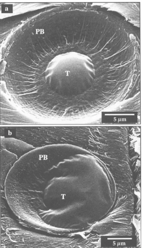
Figure 9 shows a typical view of a bordered pit from an unimpregnated specimen with the torus membrane situated in the extreme positions. The bordered pit in Fig. 9a, which is fully unaspirated, is claimed to offer an important flow path for liquids, whereas the pit structure in Fig. 9b presents an effective obstacle. Although the pit membrane shown in Fig. 9a is not representative for dry wood produced com- mercially (it was dried using a solvent-exchange technique), it does show the approximate size of the micropores that liquids are forced to pass through if the pit were to be imperfectly aspirated. However, it is also thought that speci- men preparation techniques used may result in the condi- tion shown in Fig. 9a, containing artifacts such as the micropores being of exaggerated size due to formation of cracks in the surrounding fibril network.
Figure 10 shows a corresponding area from epoxy-im- pregnated pine sapwood. As can be seen in Fig. 10a, the aspirated torus membrane effectively blocks the flow of epoxy, whereas in Fig. 10b the penetrant has partly filled
Fig. 9. Earlywood bordered pits from pine sapwood, a Unaspirated state, b Aspirated state
the cavity of the bordered pit pair, but the sealing mem- brane restricts any further flow.
Although there is evidence of liquid flow through the irregular network that surrounds the torus, the general con- clusion fi'om this study must be that viscous flow would be somewhat restricted through these micropores. Instead, a damage hypothesis is proposed 21'22 stating that viscous flow in wood, in addition to the particular state of the torus membranes, is also governed by damage introduced during the impregnation procedure. By applying the damage hyphothesis to the species used in this investigation, in which the ray morphology differs markedly, a lower perme- ability of spruce is expected.
Conclusions
Fig. 10. Bordered pits (earlywood) of epoxy-impregnated pine sap- wood. PB, bordered pit pair; T, toms membrane
The results obtained can be summarized as follows. For pine sapwood, liquid flow is enabled through disrupted pinoid pit membranes (cross-field pits), which divide the longitudinal tracheids and the parenchymatous ray cells. The main mechanism accounting for the reduced perme- ability of pine heartwood is believed to be deposits of higher-molecular-weight substances (extractives) on the cell walls and in the parenchymatous ray cells. For spruce, the thicker ray cells in combination with the smaller pits, which are connected to the longitudinal tracheids, severely reduce permeability.
Acknowledgments The authors thank the Swedish National Board for Industrial and Technical Development (NUTEK) and the European Regional Development Fund for financial support for this work.
References
1. Richardson B A (1993) Wood preservation. Cambridge University Press, Cambridge, UK
2. Hart CA, Thomas RJ (1967) Mechanism of bordered pit aspiration as caused by capillarity. For Prod J 17(11):61-68
3. Comstock GL, C6td W A (1968) Factors affecting permeability and pit aspiration in conferious sapwood. Wood Sci Technol 2:279- 291
4. C6t6 WA, Krahmer RL (1962) The permeability of coniferous pits demonstrated by electron microscopy. TAPPI 45:I19-122 5. Bailey PJ, Preston RD (1969) Some aspects of softwood perme-
ability. I. Holzforschung 23(2):113-120
6. Phillips WWJ (1933) Movement of the pit membrane in coniferous woods, with special reference to preservative treatment. Forestry 7:109-120
7. Liese W, Bauch J (1967) On the closure of bordered pits in coni- fers. Wood Sci Technol 1:1-13
8. Richter K, Sell J (1992) Studies on impregnation pathways in white fir (Abies alba). Holz Roh Werkstoff 50:329-336
9. Wardrop AB, Davies GW (1961) Morphological factors relating to the penetration of liquids into wood. Holzforschung 15:129-141 10. Banks WB (1970) Some factors affecting the permeability of scots
pine and Norway spruce. Wood Sci 5:10-17
11. Keith CT, Chauret G (1988) Anatomical studies of CCA penetra- tion associated with conventional (tooth) and with micro (needle) incising. Wood Fiber Sci 20:197-208
12. Greaves H (1974) Electron probe X-ray analysis of selected ana- tomical structures in copper-chrome-arsenic-treated wood. For Prod J 7(2):164-i68
13. Trenard Y, Gueneau P (1984) Penetration pathways of liquid gal- lium in wood seen by scanning electron microscopy. Wood Fiber Sci 16:403-410
14. Buro A, Buro E A (1959) The routes by which liquids penetrate into wood of Pinus sylvestris. Holzforschung 13(3):71-77 15. Liese W, Bauch J (1967) On anatomical causes of the refractory
behaviour of spruce and Douglas fir. Wood Sci 19:3-14
16. Erickson HD, Balatinecz JJ (1964) Liquid flow paths into wood using polymerization techniques: Douglas-fir and styrene. For Prod J 14:293-299
17. Omidvar A, Schneider MH, Van Heiningen ARP (t997) Probing red maple pit membrane pore size at fiber saturation point and oven dry using polystyrene macromolecules. Wood Sci Technol 31:235-240
18. Smulski S, C6t6 WA (1984) Penetration of wood by a water-borne alkyd resin. Wood Sci Technoi 18:59-75
19. Moore GR, Kline DE, Blankenhorn PR (1983) Impregnation of wood with a high viscosity epoxy resin. Wood Fiber Sci 15:223- 234
20. Behr EA, Sachs IB, Kukachka BF, Blew JO (1969) Microscopic examination of pressure-treated wood. For Prod J 19(8):31-40 21. Olsson T, Megnis M, Varna J, Lindberg H (2001) Measurement of
the up take of linseed oil in pine by the use of X-ray microdensito- metry technique. J Wood Sci 47:275-281
22. Megnis M, Olsson T, Varna J, Lindberg H (1999) Mechanical performance of linseed oil impregnated pine as correlated to the take up level. (Submitted)
23. Erickson HD (1970) Permeability of southern pine wood - a review. Wood Sci 2(3):149-158
24. Bauch J, Schweers W, Berndt H (1974) Lignification during heart- wood formation: comparative study of rays and bordered pit mem- branes in coniferous woods. Holzforschung 28(3):86-91
25. Bamber RK, Fukazawa K (1985) Sapwood and heartwood: a review (abstract). Forestry 46:567-580
26. Nyr6n V, Back E (1960) Characteristics of parenchymatous cells and tracheidal ray cells in Picea Abies Karst: the resin in parenchy- matous cells and resin canals of conifers VI. Svensk Papperstidning 63:501-509