RESEARCH ARTICLE
Flexural Response of Reinforced
Concrete Beams Strengthened
with Near-Surface-Mounted Fe-Based
Shape-Memory Alloy Strips
Kinam Hong
1, Sugyu Lee
1*, Yeongmo Yeon
1and Kyusan Jung
2Abstract
This paper proposes an advanced near-surface-mounted (NSM) technique with an Fe-based shape-memory alloy (Fe-SMA) strip which can solve issues of low workability and reduced ductility of reinforced concrete (RC) beams strengthened with an NSM technique using prestressed fiber-reinforced polymer (FRP) strips in the concrete ten-sion section. The flexural behavior of the RC beam strengthened by the NSM technique with the Fe-SMA strip was investigated. A total of seven RC beams were tested by four-point bending tests under displacement control. The type of reinforcements, the quantity of Fe-SMA strips, and the pre-straining level of the Fe-SMA strips were considered as experimental variables. Cracking load, yielding load, and ultimate load increased, respectively, with larger quantities of Fe-SMA strip. In addition, activation of embedded Fe-SMA in the concrete by electrical resistance heating effectively induces a prestressing force on the concrete beam, resulting in a cambering effect. The introduced prestressing force to the RC beam by activation of the Fe-SMA increased the crack and yielding loads, and did not decrease the ductility of the RC beam compared to the RC beam with non-activated Fe-SMA. It can be concluded from the test results that the strengthening technique using the recovery stress of the Fe-SMA strip as the prestressing force solves the various problems of the existing prestressing strengthening systems, meaning that Fe-SMA can be used as a substitute for conventional prestressing strengthening systems.
Keywords: NSM reinforcing method, prestressed strengthening material, Fe-SMA strip, pre-straining level, prestressing force, ductility
© The Author(s) 2018. This article is distributed under the terms of the Creative Commons Attribution 4.0 International License (http://creat iveco mmons .org/licen ses/by/4.0/), which permits unrestricted use, distribution, and reproduction in any medium, provided you give appropriate credit to the original author(s) and the source, provide a link to the Creative Commons license, and indicate if changes were made.
1 Introduction
Various materials and techniques have been developed to strengthen damaged or deteriorated civil structures. Fiber reinforced polymer (FRP) sheets and plates are the most widely used strengthening materials
(Trian-tafillou and Plevris 1992; Elsanadedy et al. 2013; Loreto
et al. 2013). The most common strengthening techniques
used for deteriorated structures are external bonding
reinforcement (EBR) and near-surfaced-mounted (NSM)
methods (Kim 2015). The EBR technique is a
strength-ening method that improves structural performance by attaching steel or FRP plates on the surface of a structure. However, the strengthening material in the EBR method is exposed, making it vulnerable to damage due to fire or corrosion. Furthermore, different thermal coefficients of the concrete and the material can cause debonding, leading to a premature failure of either the epoxy resin
matrix or the strengthening material (Park 2003; Kim
2005; Barros et al. 2006; Casadei et al. 2006; Choi et al.
2010; Hong et al. 2014; Bilotta et al. 2015; Coelho et al.
2015). NSM technology was proposed to overcome such
problems of the EBR method. NSM involves inserting strengthening materials such as FRP bars, FRP strips, or
Open Access
*Correspondence: [email protected]
1 Department of Civil Engineering, Chungbuk National University, 1 Chungdae-ro, Seowon-Gu, Cheongju 28644, Chungbuk, Republic of Korea
steel strands into the grooves of concrete cover which needs to be strengthened, and then bonding the strength-ening material with a cement mortar or epoxy resin
matrix as a filler inside a groove (De Lorenzis et al. 2002;
El-Hacha and Rizkalla 2004; El-Hacha and Gaafar 2011;
El-Hacha and Soudki 2013). Recently, various researches
on the strengthening civil structures using FRP materi-als for NSM methods have been conducted (El-Hacha
and Rizkalla 2004; Gaafar and El-Hacha 2008; El-Hacha
and Gaafar 2011; El-Hacha and Soudki 2013). Even
though researches have not found a way to completely solve the premature failure of the strengthening mate-rial in the EBR method, the considerable improvement of the flexural behavior of reinforced concrete (RC) beams strengthened by the NSM method compared to the RC beams strengthened by the EBR method has been dem-onstrated. Prestressing strengthening methods (PSMs) are used for concrete which needs to improve its flexural behavior in terms of serviceability and deflection (Yang
et al. 2009). For decades, PSMs have been performed by
fastening the post-tensioned material on the tensile side
of a concrete beam (Rosenboom and Rizkalla 2006).
Compressive stresses at the bottom of the concrete mem-ber and tensile stresses at the top of the concrete memmem-ber are produced by the prestressing force transmitted from the prestressed strengthening material, which is known as
the cambering effect (El-Hacha et al. 2001). The RC beam
strengthened by the prestressed strengthening material has various advantages, such as reducing both deflection and crack width, increasing load-carrying capacity, and
resistance of fatigue failure (El-Hacha et al. 2001; Woo
et al. 2008). Among the PSMs, the NSM technique using
prestressed FRP material, referred to as prestressed FRP NSM, has been studied by many researchers failure
(El-Hacha et al. 2001; Nordin 2003; Hong et al. 2006; Woo
et al. 2008). It has been reported that the prestressed FRP
NSM technique increases cracking and yielding loads and reduces deflection at mid-span and crack width for the strengthened RC beams. However, this technique faces the critical problem of reduced ductility of the
strengthened RC beam (Badawi and Soudki 2009). The
ductility of the strengthened RC beam is reduced with higher prestressing level of the prestressed FRP material, which finally causes failure at a smaller deflection. The reason for this is that a large part of the strain capacity of the FRP reinforcement is already used during prestress-ing. The deformability of the RC beam strengthened by prestressed FRP material is greatly reduced, resulting in all specimens being strengthened by the prestressed FRP material failing by rupture of the FRP material
(Rezaza-deh et al. 2015; Kara et al. 2016). The decreased
ductil-ity of the strengthened RC beam is because of increased tensile reinforcement and the prestressing effect, which
leads to less energy dissipation. Furthermore, in the pre-stressed FRP NSM technique, it is difficult to assign and secure the FRP material in the groove and to apply a
pre-tension force in the groove (Shahverdi et al. 2016). This
is the reason why the prestressed FRP NSM technique is not widely used in practice.
The NSM technique using shape-memory alloys (SMAs) can be an alternative way to solve the abovemen-tioned problems of the prestressed FRP NSM technique. SMAs are very widely known unique materials which have the ability to return to a pre-defined (memorized) shape when heated to a certain temperature, which is called the shape-memory effect (SME). An NiTi-based SMA (NiTi-SMA) having the SME and super elasticity is used in various fields such as the aerospace and medical
industries (Miller and Lagoudas 2000). However, it is not
feasible to use the NiTi-SMA as the strengthening mate-rial for retrofitting civil structures because of its high production cost. Fe-based SMAs (Fe-SMAs) were devel-oped by Sato et al. in 1982, and their wide shape-memory capacity was subsequently studied by many
research-ers (Sato et al. 1982; Kajiwara et al. 2001; Farjami et al.
2004; Dong et al. 2009; Lee et al. 2013). Since the 2000s,
Fe-SMA material to strengthen civil structures has been
researched (Abdulridha et al. 2013; Cladera et al. 2014;
Czaderski et al. 2014; Shahverdi et al. 2016). Deformation
recovery of an embedded Fe-SMA strip in concrete is restrained, resulting in compressive force—namely pre-stressing force.
The most attractive advantage of using the Fe-SMA NSM technique is that no frictional loss at initial pre-stressing stage occurs because uniform compression is generated along the entire length of the Fe-SMA strip, and the prestress loss due to creep and drying shrinkage can be easily recovered by re-applying electric resistance
heating to the Fe-SMA strip (Shin and Andrawes 2010).
This paper presents a study on the feasibility of Fe-SMA strips as an NSM strengthening material for civil structures. The purpose of this paper is to acquire greater flexural capacity and ductility of RC beams by employ-ing the Fe-SMA NSM technique. The flexural behavior of seven RC beams was investigated with four-point bend-ing tests. The type of reinforcement material, the number of SMA strips, and the pre-straining level of the Fe-SMA strips were considered as experimental variables.
2 Experimental Program 2.1 Test Specimens
A total of seven RC beams were produced to evaluate the flexural behavior of RC beams strengthened with the Fe-SMAs using the NSM technique. The
cross-sec-tion of the specimens was 300 mm × 200 mm, and the
specimens had a total length and a net length of 3000 and 2700 mm, respectively. Three deformed steel bars with a nominal diameter of 10 mm were embedded in the RC beam as tensile reinforcements for restraining the opening of flexural cracks. For shear, no stirrup was required because of a sufficient shear-loading capacity
by the concrete web member. Figure 1 presents
speci-men details.
The type of strengthening, the number of the Fe-SMA strips, and the pre-straining levels of the Fe-Fe-SMA strips were considered as experimental variables. A carbon fiber reinforced polymer (CFRP) strip and the Fe-SMA strip were used as the strengthening materials. The cross-sectional areas of the Fe-SMA strips were 30,
60, and 90 mm2, respectively. The Fe-SMA strips were
stretched by up to 0.0, 2.0, and 4.0% of the pre-straining
levels. In Table 1, the specimens were named
accord-ingly: the first term “SL” represents the slab beam, the second term “60S” refers to the cross-sectional area of the Fe-SMA strip, and the CFRP strip was denoted as “60C”. The third term “2” represents the pre-straining level of the Fe-SMA strip. For example, “SL-60S-2” denotes the slab beam strengthened with the NSM method using the Fe-SMA strip which was pre-strained
of 2.0%. All test variables are given in Table 1.
Further-more, an un-strengthened beam with the strengthening material was fabricated and named as “SL-CTRL.”
2.2 Materials Used
The Fe-SMA used in this study was manufactured by R-Company (Switzerland). The Fe-SMA plate had a width and a thickness of 100 mm and 1.5 mm, respectively. The Fe-SMA plate was cut into tensile specimens with a
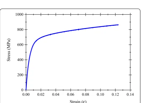
width of 10 mm and a length of 330 mm. Figure 2 shows
the stress–strain responses of the Fe-SMA strip from the
direct tensile tests. In Fig. 2, 0.2% offset yielding point
method was applied to define the modulus of elasticity
150 1100 500 1100 150 300
20
0
3-Φ10
P/2 P/2
(unit: mm) SG
SG: Strain gauge
30
LVDT CL
Fig. 1 Specimen details.
Table 1 Test variables.
Specimen ID Strengthening
material Strengthening material area (mm2) The number of strengthening materials Pre-strain (%)
SL-CTRL – – – –
SL-60C-0 CFRP strip 60 2 0
SL-30S-4 Fe-SMA strip 30 1 4
SL-60S-0 Fe-SMA strip 60 2 0
SL-60S-2 Fe-SMA strip 60 2 2
SL-60S-4 Fe-SMA strip 60 2 4
SL-90S-4 Fe-SMA strip 90 3 4
0.00 0.02 0.04 0.06 0.08 0.10 0.12 0.14 0
200 400 600 800 1000
Stress (MPa
)
Strain (ε)
since a yield point on the stress–strain response of the
Fe-SMA strip was not easily defined. In Table 2, the
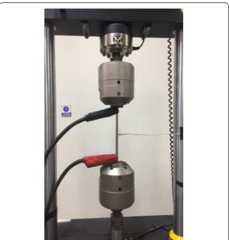
mechan-ical properties of the Fe-SMA strip are summarized. To evaluate the recovery stress of the exposed Fe-SMA strip, the Fe-SMA strips were stretched to 2.0 and 4.0%
of the pre-straining level (Fig. 3). After the strain of this
strengthening material reached the target strain value, the tensile load was totally removed. In order to avoid buckling failure due to the thermal expansion effect on the Fe-SMA strip, a pre-tensile stress of 50 MPa, conserv-atively calculated using the coefficient of thermal-expan-sion on it, was applied. An electric pulse with a density
of 2 A/mm2 was applied to create electric resistance
heating on the Fe-SMA strip. After the applied tempera-ture by electric resistance heating reached 160 °C, the electric resistance heating system was turned off to cool the heated Fe-SMA strip to ambient temperature. The temperature on the mid-length of the Fe-SMA strip was assessed with an insulating K-type thermocouple, and the recovery stress was calculated with the tensile force divided by the nominal area of the Fe-SMA strip. The tensile force was measured with a load cell in the tensile
test machine. Figure 4 shows a diagram of the recovery
stress on the temperature of the exposed Fe-SMA strip. The recovery stresses of the exposed Fe-SMA strip with 2.0 and 4.0% pre-straining level were 308 and 348 MPa, respectively. With this result, it could be concluded that an insignificant correlation was shown between the pre-straining level and the recovery stress of the exposed Fe-SMA strip.
The RC beam specimens were fabricated with a
ready-mixed concrete. Table 3 presents the mixture
properties of the concrete used in terms of water– cement ratio (W/C), sand percent of total aggregate by volume (S/a), water (W), cement (C), sand (S), gravel (G), and water-reducing admixture (Ad). The maximum aggregate size of the concrete mixture was 25 mm, and the slump and the compressive strength were 150 mm and 28 MPa, respectively. To confirm the compressive
strength of the concrete, three cylinders of ∅100 mm
were cast in accordance with ASTM C39/39 M (ASTM
2001) at the time of the RC beam casting. The cylinders
were cured with identical curing conditions to the RC
beams. The averaged compressive strength of the cylin-der specimens was 32.3 MPa at 28 curing days.
Mechanical properties of the steel rebar as the tensile reinforcement were investigated by a direct tensile test. The direct tensile tests with three deformed steel rebars with a nominal diameter of 10 mm were conducted in
accordance with ASTM A370 (ASTM 2016b), resulting
in 200 GPa, 480 MPa, and 590 MPa of modulus of elas-ticity, yielding strength, and ultimate strength, respec-tively. The mentioned mechanical properties of the
steel rebar are given in Table 4.
Table 2 Mechanical properties of Fe-SMA.
Modulus of elasticity (MPa)
Strain corresponding to yield strength (mm/ mm)
Yield strength (MPa)
Ultimate strength (MPa)
Elongation (%)
1.33 × 10⁵ 0.00547 463 863 12.4
Fig. 3 Electric resistance heating of exposed Fe-SMA.
In this paper, a rapid hardening cement was used to bond the Fe-SMA strengthening material to the concrete. Additionally, it was used as a filler for the groove on the concrete cover. According to ASTM C1329 (ASTM
2016a), the compressive strength of the rapid hardening cement was measured, resulting in 25 MPa at 2 h, 30 MPa at 3 h, 40 MPa at 24 h, and 80.5 MPa at 28 days.
2.3 Strengthening Procedure
2.3.1 Pre‑strain
The Fe-SMA strip was cut with a size of 1.5 mm thick-ness, 20 mm width, and 3000 mm length. To avoid struc-tural damage of the Fe-SMA strip caused by frictional resistance heating, a water-jet cutting machine was employed. As an additional step, mechanical sandblast-ing on the surface of the Fe-SMA strip was performed to increase the bonding strength between the Fe-SMA strip and the rapid hardening cement mortar. In order to max-imize the recovery stress on the SMA strip, the cut Fe-SMA strip was stretched up to 2.0 and 4.0% by using a
tensile machine, as shown in Fig. 5. This machine consists
of two parts: the end anchor to fasten the Fe-SMA strip and the hydraulic tensioning system to apply the pre-ten-sile stress on the Fe-SMA strip. The applied pre-tenpre-ten-sile
force was maintained for 30 s to make the Fe-SMA strip stable, and then removed until the residual stress on the Fe-SMA strip reached zero. Residual strains of 2.0 and 4.0% of the pre-strained Fe-SMA strip, after the tension force was completely removed, were 1.07 and 2.92%, respectively, which were close to the residual strains
esti-mated by Yeon’s equation (Yeon 2017). The Fe-SMA strip
was punched with a 10 mm diameter hole which was 20 mm away from both ends to connect copper clips for
supplying the electricity (see Fig. 7a). As well as the
cop-per clips, insulating K-type thermocouples for assessing the temperature on the surfaces of the Fe-SMA strip at mid-length were used.
2.3.2 Embedding Fe‑SMA Strip
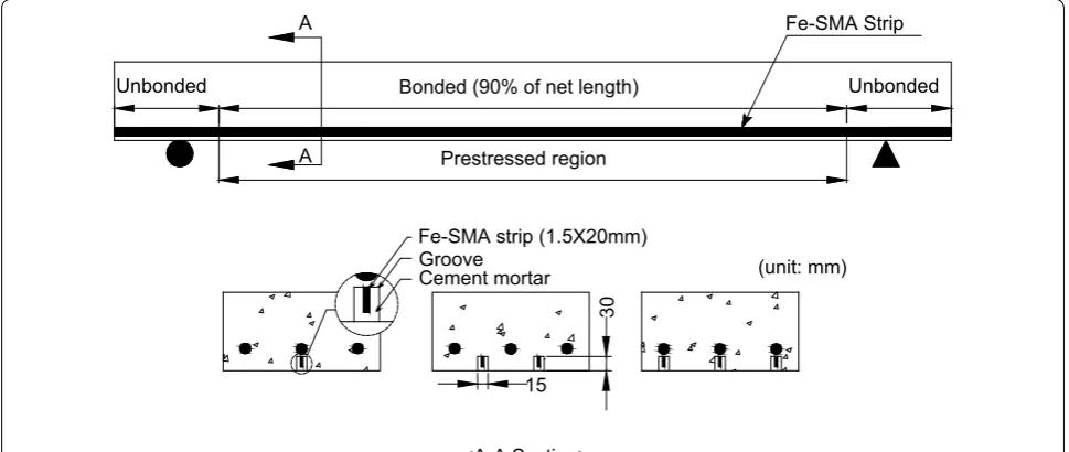
The Fe-SMA strengthening material was inserted in a groove fabricated in the concrete cover with the rapid hardening cement mortar. The groove with a size of
15 × 30 mm was fabricated along the length of the RC
beam in the tension region by a grooving machine. As
shown in Figs. 6 and 7, the Fe-SMA strip was
embed-ded with a length of 2430 mm, which is 90% of the net length in the groove with the cement mortar. This means that the prestressing force was applied on 90% of the net length to prevent crack developments at the tension region due to excessive negative moment at the mid-span during prestressing.
2.3.3 Activation of Fe‑SMA
To activate the Fe-SMA strip embedded in the RC beam, the RC beam was placed at the center of the
Table 3 Mixture design of concrete used.
a Maximum gravel size. b Water-reducing admixture.
W/C (%) S/a (%) Gmax (mm)a Slump (mm) Unit weight (kg/m3)
W C S G Adb
42.3 50.4 25 150 164 388 954 908 3.1
Table 4 Mechanical properties of the steel rebar used.
Modulus of elasticity (MPa)
Nominal diameter (mm)
Yield strength (MPa)
Ultimate strength (MPa)
Elongation (%)
2.0 × 10⁵ 9.53 480 590 17.1
reaction frame, and the cables of the electric power supply were connected in series to the copper clips.
Figure 8a shows the process to activate the SME of
the embedded Fe-SMA strip with an electric density
of 10 A/mm−2. When heating the embedded Fe-SMA
strip, a restrained longitudinal displacement of the embedded Fe-SMA strip by the rapid hardening cement mortar induced recovery stress, which was introduced into the RC beam as the prestressing force. The tem-perature generated by electrical resistance heating was measured by the insulating K-type thermocou-ples attached to the surface of the embedded Fe-SMA strip, and the temperature at the bottom surface of the RC beam was measured by employing an infrared
thermometer (see Fig. 8b). During heating of the
Fe-SMA strip, to assess upward displacements induced by the prestressing force, linear variable differential transformers (LVDTs) with a capacity of 50 mm were placed at the mid-span of the RC beams. Furthermore, strain values at the tension region corresponding to the upward displacement were measured with a strain gauge installed 30 mm away from the top mid-surface. The electrical resistance temperature was applied to 160 °C of the planned temperature and then stopped. The RC beam specimen was cured indoors until the upward displacement caused by the cambering effect was stable.
Unbonded Bonded (90% of net length) Unbonded
15 Prestressed region
Fe-SMA Strip A
A
Groove Cement mortar
Fe-SMA strip (1.5X20mm)
30
<A-A Section>
(unit: mm)
Fig. 6 Details of the bonded Fe-SMA inside the concrete beam.
2.4 Test Setup
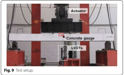
The RC beam specimens were loaded with 2000 kN of an actuator capacity at a stroke speed of 3 mm/min, and were tested under a four-point loading system. The net length and the distance between two loading points were 2700 and 500 mm, respectively. Two LVDTs were placed on the lower surface of the specimen to measure the deflection at mid-span. To assess the strain values of the concrete and the tensile reinforcements, strain gauges were attached on them at the mid-span section. The measured data such as load, mid-deflection, and strains from the concrete and tensile reinforcements were
recorded at a frequency of 1 s by a data logger. Figure 9
shows the overview of the test setup.
3 Result and Discussion
3.1 Cambering Effect by Prestressing Force
As aforementioned, electric resistance heating was used to activate the SME of the embedded Fe-SMA strip, which induces recovery stress under the restrained Fe-SMA strip by the cement mortar. The recovery stress
referred to as the prestressing force can be introduced as compression into the bottom of the RC beam, which causes upward displacement (cambering effect). The electric resistance heating temperature and the corre-sponding vertical displacement diagrams across heating
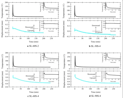
time are shown in Fig. 10 and Table 5. The embedded
Fe-SMA strips in all the RC beams were equally heated to the target temperature of 160 °C with the electric density
of 10 A/mm2. A different heating time was required (45,
75, and 122 s) depending on the Fe-SMA strip’s
cross-sectional area (30, 60, and 90 mm2). After reaching the
target temperature of 160 °C, the RC beam specimens strengthened, with the Fe-SMA strips cooled until the surface temperature of the embedded Fe-SMA strips reached ambient temperature to acquire sufficient pre-stressing force from the embedded Fe-SMA strip. The RC beams strengthened by the prestressed Fe-SMA NSM technique showed two different behaviors of deflection. At the beginning of heating the Fe-SMA strip, the down-ward displacements of SL-60S-2, SL-30S-4, SL-60S-4, and SL-90S-4 were 0.097, 0.114, 0.134, and 0.151 mm at the mid-span, respectively, due to the thermal expan-sion effect of the embedded Fe-SMA strips in the RC beams. The downward displacements were restored after the completely activated SME of the Fe-SMA strips, and then upward displacement occurred due to the camber-ing effect by the prestresscamber-ing force for about 250 min. The final upward displacements of SL-60S-2, SL-30S-4, SL-60S-4, and SL-90S-4 were 0.205, 0.218, 0.443, and 0.625 mm, respectively.
The strain value of the Fe-SMA strips using the strain gauge was not directly acquired because of the higher surface temperature of 160 °C and the high voltage pass-ing through the Fe-SMA strip durpass-ing the activation for
Fig. 8 Activation of embedded Fe-SMA in a concrete beam.
the SME. Therefore, the prestressing strength was calcu-lated with the upward displacement and flexural rigidity and modulus of elasticity of the RC beams. The equations
for the prestressing strength are expressed in Eqs. (1)–
(8) below. The bonding length with the rapid hardening
cement mortar was taken into account in Eqs. (1)–(8).
The effects of shrinkage, creep, and self-weight of the RC beam specimen for calculating the prestressing strength
were ignored. As shown in Fig. 11, the embedded
Fe-SMA strip at the bottom of the concrete beam causes the recovery stress due to the SME, which induces the compression force (prestressing force). This compressive force generates a constant negative moment along the bonding length of the Fe-SMA strip.
(1) δ= Ml0(l−l0)
4EI +
Ml02 8EI
(2)
M=8EIδ 1
l0(l−l0)+l02
(3) M=Precoverye=ASMAσrecoverye
a SL-60S-2 b SL-30S-4
c SL-60S-4 d SL-90S-4
0 50 100 150 200
0 50 100 150 200 250 -0.4 -0.2 0.0 0.2 0.4 Temperature (C ) Displacement (mm) Time (min) Upward Downward
0 5 10 15 20 -0.50
-0.25 0.00 0.25
Displacement (mm) Time (min) 0 5 10 15 20 0 50 100 150 Temperature ( C) Time (min) 0 50 100 150 200
0 50 100 150 200 250 -0.2 0.0 0.2 0.4 Temperature ( C) Upward ) m m( tn e me cal psi D Time (min) Downward
0 5 10 15 20 -0.50
-0.25 0.00 0.25
Displacement (mm) Time (min) 0 5 10 15 20 0 50 100 150 Temperature ( C) Time (min) 0 50 100 150 200
0 50 100 150 200 250 -0.6 -0.4 -0.2 0.0 0.2 0.4 Temperature (C ) Displacement (mm) Time (min) Upward Downward
0 5 10 15 20 -0.50
-0.25 0.00 0.25
Displacement (mm) Time (min) 0 5 10 15 20 0 50 100 150 Temperature (C ) Time (min) 0 50 100 150 200
0 50 100 150 200 250 -0.8 -0.6 -0.4 -0.2 0.0 0.2 0.4 Temperature (C ) Displacement (mm) Time (min) Upward Downward
0 5 10 15 20 -0.50
-0.25 0.00 0.25
Displacement (mm) Time (min) 0 5 10 15 20 0 50 100 150 Temperature (C ) Time (min)
Fig. 10 Activation temperature and displacement curves across time.
Table 5 Summary of displacement by activation.
Specimen SL-60S-2 SL-30S-4 SL-60S-4 SL-90S-4
Downward (mm) 0.097 0.114 0.134 0.151
where l0 : length of embedded Fe-SMA strip with cement
mortar (mm); l : net span of reinforced beam (mm); M :
moment induced by prestressing force (kN m); σrecovery :
Recovery stress induced by shape-memory effect of
Fe-SMA (MPa); e : eccentric distance (mm); Precovery :
recov-ery force induced by prestressing force (kN); δ : deflection
at mid-length of beam (mm); ASMA : nominal area of
Fe-SMA (mm2); EI : flexural rigidity of reinforced beam (kN
m2).
where Ec : modulus of elasticity of concrete (MPa); Es :
modulus of elasticity of steel (MPa); n : modulus of
elas-ticity transformation coefficient for steel to concrete; c :
distance from the top to the neutral axis of a concrete
beam (mm); d : effective depth from the top of a
rein-forced concrete beam to the centroid of the tensile steel
(mm); dSMA : effective depth from the top of a reinforced
concrete beam to the centroid of the Fe-SMA strip (mm);
δ : deflection at mid-length of beam (mm).
The ratio of the recovery stress of the exposed
Fe-SMA strip, σre,ex , to that of the embedded Fe-SMA
strip, σre,em , is shown in Table 6. The ratio of the
recov-ery stresses ranged from 0.992 to 1.191, which indicates that the recovery stress of the embedded Fe-SMA strip was effectively transferred to the RC beam as the pre-stressing force. Therefore, it is worth mentioning that the Fe-SMA strip activated with electric resistance heating can easily introduce prestressing force in the concrete
(4) σrecovery=
8EIδ
ASMAe
l0(l−l0)+l20
(5)
Ec=85003
fcu
(6) n= Es
Ec
(7)
c= 0.5bh
2+(
n−1)Asd
bh+(n−1)As
(8) e=dSMA−c
member rather than the conventional mechanical pre-stressing technique which requires additional equipment such as a hydraulic jack and an end anchor. However, the increase of the number of Fe-SMA strips requires more heating time for the activation of the SME, resulting in the concrete member and Fe-SMA strip expansion. This phenomenon might reduce the recovery stress of the strengthened RC beam.
3.2 Flexural Behavior of RC Beam
3.2.1 Failure Mode
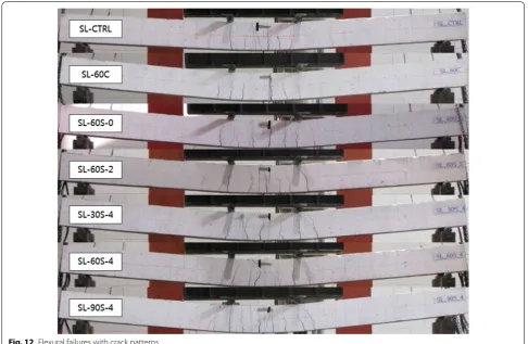
Figure 12 shows the failure modes of the specimens after
the tests. For the specimen strengthened by the CFRP strip, a slippage failure occurred before reaching yield-ing load. The reason for this is that the bondyield-ing strength at the interface between the CFRP strip and the cement mortar was not sufficient to endure the slippage. Except for the specimen strengthened with the CFRP strip, all other specimens failed by forming cracks at mid-span and the yielding of tensile steel rebar followed by the concrete crushing of the compression zone. Initial cracks were observed at the mid-span and developed toward the compression zone. With the increase of the quantity of the Fe-SMA strengthening materials, the number of developed cracks increased, and the averaged width of cracks decreased.
3.2.2 Responses of Load and Displacement
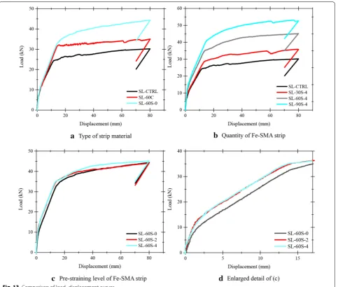
Table 7 and Fig. 13 show the responses of load and
dis-placement at the mid-span of all specimens. Figure 13a
is a comparison of the load–displacement responses depending on the type of reinforcement. RC beam specimens strengthened with no strengthening mate-rial (SL-CTRL), CFRP strip (SL-60C-0), and Fe-SMA
Fig. 11 Schematic of camber deflection by prestressing force.
Table 6 Comparison of recovery stresses of Fe-SMA strips.
Specimen σre,ex (MPa) σre,em (MPa) σre,ex/σre,em
SL-60S-2 347.5 354.93 0.98
SL-30S-4 401.5 366.82 1.09
SL-60S-4 401.5 372.71 1.08
strip (SL-60S-0), respectively. The pre-straining was not applied on these Fe-SMA strips. It was observed that the change of stiffness, after initial cracks, occurred in all specimens. For cracking loads, initial cracks of SL-CTRL were shown at 7.42 kN, whereas SL-60C-0 started to crack at approximately 10.03 kN, and SL-60S-0 showed initial cracking at 9.94 kN. The crack-ing loads of SL-60C-0 and SL-60S-0 increased by 35.17 and 33.96%, respectively, compared to that of SL-CTRL. This might be because the larger modulus of elasticity of strengthening can effectively control the crack develop-ments. The yielding load of SL-60S-0 was increased by
34.89% compared to that of SL-CTRL. Unfortunately, for SL-60C-0, the premature slippage failure at 31.05 kN occurred before the tensile reinforcement yielded, and no significant increase of the load was shown thereafter. In contrast, the Fe-SMA strip with the sandblasted surface showed sufficient bonding strength to the cement mortar. The ultimate load of SL-60S-0 is approximately 52.98% higher than that of SL-CTRL.
Figure 13b is a comparison of the load–displacement
responses of SL-30S-4, SL-60S-4, and SL-90S-4, which are specimens with different cross-sectional areas of
Fe-SMA strip: 30, 60, and 90 mm2. In Fig. 13b, SL-CTRL was
plotted and compared with other specimens. The crack-ing loads of SL-30S-4, SL-60S-4, and SL-90S-4 increased by 26.95, 81.40, and 89.22%, respectively, compared to that of SL-CTRL. With such results, it can be concluded that the increase in quantity of the strengthening mate-rials showed a positive crack control effect. The yielding loads of SL-30S-4, SL-60S-4, and SL-90S-4 increased by 19.71, 43.0, and 74.11%, respectively, compared to that of SL-CTRL. The reason for this is that the increased
area of 30 mm2 increased the stiffness after initial
crack-ing occurred. The ultimate loads showed a similar trend with the yielding loads. The ultimate loads of SL-30S-4,
Fig. 12 Flexural failures with crack patterns.
Table 7 Summary of experimental test results.
Specimen Pcrack (kN) Pyield (kN) Pultimate (kN)
SL-CTRL 7.42 23.79 29.56
SL-60C-0 10.03 31.05 34.73
SL-60S-0 9.94 32.09 45.22
SL-60S-2 11.52 33.12 44.23
SL-60S-4 13.46 34.02 46.64
SL-30S-4 9.42 28.48 36.78
SL-60S-4, and SL-90S-4 increased by 24.42, 57.78, and 87.45%, respectively, compared to that of SL-CTRL. The ultimate load increased by an average of 30.0% by
increase of the area of 30 mm2.
Figure 13c shows a comparison of the
load–displace-ment curves of the specimens strengthened with
differ-ent pre-straining levels on 60 mm2 area of the Fe-SMA
strip. The Fe-SMA strips were pre-strained to 0.0, 2.0, and 4.0% of SL-60S-0, SL-60S-2, and SL-60S-4, respec-tively. The cracking loads of SL-60S-2 and SL-60S-4 increased by 15.89 and 35.41%, respectively, compared to that of SL-60S-0. This result might be because the intro-duced prestressing force to the tension region of the con-crete increased the flexural rigidity and delayed initial crack development. However, the yielding loads of SL-60S-2 and SL-60S-4 increased slightly by 3.21 and 6.01% compared to the yielding load of SL-60S-0. However, it
would be noted that similar to the characteristic of con-ventional prestressed RC beams with strengthening materials, the RC beam strengthened with the Fe-SMA NSM technique showed an insignificant increase of the ultimate loads with higher pre-straining levels of the Fe-SMA strips. Additionally, the RC beam strengthened with the Fe-SMA NSM technique did not show a reduc-tion of ductility by introducing prestressing force to the concrete compared to the RC beam strengthened by the prestressed FRP NSM technique. Based on those results, it would seem that the prestressing technique using the recovery stress of the Fe-SMA strip can overcome the limitations of conventional strengthening techniques using prestressed FRP plates or steel strands such as difficult-to-apply pre-tension force, required equipment for anchoring, and reduced ductility of the strengthening material.
4 Conclusions
This paper investigated the flexural behavior of RC beams strengthened with the Fe-SMA NSM technique. The following conclusions are drawn from the results.
1. RC beams strengthened with Fe-SMA strips were deflected downward by thermal expansion of the heated Fe-SMA strip. However, after heating to the target temperature of 160 °C, the strengthened RC beam was cooled down to ambient temperature, resulting in the recovery stress—namely prestressing force. The prestressing force acted as compression to the tension region of the concrete, which generated the cambering effect. The ultimate upward displace-ments at mid-span of the strengthened RC beams by the cambering effect were 0.205, 0.218, 0.443, and 0.625 mm, respectively, for 60S-2, 30S-4, SL-60S-4, and SL-90S-4.
2. The ratios of the recovery stress of the exposed Fe-SMA strip to that of the embedded Fe-Fe-SMA strip were 0.979–1.169, which indicates that the recov-ery stress of the embedded Fe-SMA strip was effec-tively transferred to the concrete beam as prestress-ing force. Therefore, it is worth mentionprestress-ing that the activated Fe-SMA strip by electric resistance heating can easily introduce the prestressing force in the con-crete member rather than the conventional mechani-cal prestressing technique which requires additional equipment such as a hydraulic jack and an end anchor.
3. Cracking loads of the RC beams strengthened with 2.0 and 4.0% pre-strained Fe-SMA strips, SL-60S-2 and SL-60S-4, increased by 15.89 and 35.41% com-pared to that of the specimen with non-activated Fe-SMA, SL-60S-0. Additionally, the flexural rigidity of SL-60S-2 and SL-60S-4 significantly increased com-pared to that of SL-60S-0.
4. Similar to the general characteristic of the RC beam strengthened with steel strands, the RC beam strengthened by the prestressed Fe-SMA NSM tech-nique showed insignificant increase of ultimate loads. Furthermore, the prestressed Fe-SMA NSM tech-nique did not reduce the ductility of the strengthened RC beams by introducing the prestressing force to the concrete compared to the RC beam strengthened by the prestressed FRP NSM technique.
5. Finally, the strengthening technique using the recov-ery stress of the Fe-SMA strip as the prestressing force solves various problems with existing prestress-ing strengthenprestress-ing systems, meanprestress-ing that Fe-SMA can be used as a substitute for conventional prestressing strengthening systems.
5 Availability of Data and Material
All data is available to all of research community.
Author Contributions
Yeongmo Yeon and Kyusan Jung conducted the experiments and wrote the initial draft of the manuscript. Ki-Nam Hong and Sugyu Lee analyzed the data and wrote the final manuscript. All authors contributed to the analysis of the data and read the final paper.
Author details
1 Department of Civil Engineering, Chungbuk National University, 1 Chungdae-ro, Seowon-Gu, Cheongju 28644, Chungbuk, Republic of Korea. 2 Structural Engineering Research Institute, Korea, Institute of Civil Engineer-ing and BuildEngineer-ing Technology, 283 Daehwa-dong, Goyangdae-ro, Ilsanseo-gu, Goyang-si 10223, Gyeonggi-do, Republic of Korea.
Acknowledgements
This research was supported by a grant (17CTAP-C115171-02) from Technol-ogy Advancement Research Program (TARP) funded by Ministry of Land, Infrastructure and Transport of Korean government.
Conflicts of interest
The authors declare no conflict of interest.
Ethical Approval
For this type of study formal consent is not required.
Received: 24 March 2018 Accepted: 27 April 2018
References
Abdulridha, A., Palermo, D., Foo, S., & Vecchio, F. J. (2013). Behavior and mod-eling of superelastic shape memory alloy reinforced concrete beams. Engineering Structures,49, 893–904.
ASTM, C39. (2001). Standard test method for compressive strength of cylindrical concrete specimens. West Conshohocken, PA: ASTM International. ASTM, C370-12. (2016a). Standard test method for moisture expansion of fired
Whiteware products. West Conshohocken, PA: ASTM International. ASTM, C1329-16a. (2016b). Standard specification for mortar cement. West
Conshohocken, PA: ASTM International.
Badawi, M., & Soudki, K. (2009). Flexural strengthening of RC beams with prestressed NSM CFRP rods—experimental and analytical investigation. Construction and Building Materials,23(10), 3292–3300.
Barros, J. A., Ferreira, D. R., Fortes, A. S., & Dias, S. J. (2006). Assessing the effec-tiveness of embedding CFRP laminates in the near surface for structural strengthening. Construction and Building Materials,20(7), 478–491. Bilotta, A., Ceroni, F., Nigro, E., & Pecce, M. (2015). Efficiency of CFRP NSM strips
and EBR plates for flexural strengthening of RC beams and loading pat-tern influence. Composite Structures,124, 163–175.
Casadei, P., Galati, N., Boschetto, G., Tan, K. Y., Nanni, A., & Galecki, G. (2006, June). Strengthening of impacted prestressed concrete bridge I-girder using prestressed near surface mounted C-FRP bars. In Proceedings of 2nd International FIB Congress. Naples, Italy (CD-ROM, paper ID 10–76). Choi, H. T., West, J. S., & Soudki, K. A. (2010). Effect of partial unbonding on
pre-stressed near-surface-mounted CFRP-strengthened concrete T-beams. Journal of Composites for Construction,15(1), 93–102.
Cladera, A., Weber, B., Leinenbach, C., Czaderski, C., Shahverdi, M., & Motavalli, M. (2014). Iron-based shape memory alloys for civil engineering struc-tures: An overview. Construction and Building Materials,63, 281–293. Coelho, M. R., Sena-Cruz, J. M., & Neves, L. A. (2015). A review on the bond
behavior of FRP NSM systems in concrete. Construction and Building Materials,93, 1157–1169.
De Lorenzis, L., Rizzo, A., & La Tegola, A. (2002). A modified pull-out test for bond of near-surface mounted FRP rods in concrete. Composites Part B Engineering,33(8), 589–603.
Dong, Z., Klotz, U. E., Leinenbach, C., Bergamini, A., Czaderski, C., & Motavalli, M. (2009). A novel Fe–Mn–Si shape memory alloy with improved shape recovery properties by VC precipitation. Advanced Engineering Materials, 11(1–2), 40–44.
El-Hacha, R., & Gaafar, M. (2011). Flexural strengthening of reinforced concrete beams using prestressed, near-surfacemounted CFRP bars. PCI Journal, 56(4), 134–151.
El-Hacha, R., & Rizkalla, S. H. (2004). Near-surface-mounted fiber-reinforced polymer reinforcements for flexural strengthening of concrete structures. Structural Journal,101(5), 717–726.
El-Hacha, R., & Soudki, K. (2013). Prestressed near-surface mounted fibre reinforced polymer reinforcement for concrete structures—A review. Canadian Journal of Civil Engineering,40(11), 1127–1139.
El-Hacha, R., Wight, R. G., & Green, M. F. (2001). Prestressed fibre-reinforced polymer laminates for strengthening structures. Progress in Structural Engineering and Materials,3(2), 111–121.
Elsanadedy, H. M., Almusallam, T. H., Alsayed, S. H., & Al-Salloum, Y. A. (2013). Flexural strengthening of RC beams using textile reinforced mortar— Experimental and numerical study. Composite Structures,97, 40–55. Farjami, S., Hiraga, K., & Kubo, H. (2004). Shape memory effect and
crystal-lographic investigation in VN containing Fe–Mn–Si–Cr alloys. Materials Transactions,45(3), 930–935.
Gaafar, M. A., & El-Hacha, R. (2008, July). Strengthening reinforced concrete beams with prestressed near surface mounted FRP strips. In Proceedings of Fourth International Conference on FRP Composites in Civil Engineering, CICE, Zurich, Switzerland.
Hong, K. N., Cho, C. G., Lee, S. H., & Park, Y. (2014). Flexural behavior of RC mem-bers using externally bonded aluminum-glass fiber composite beams. Polymers,6(3), 667–685.
Hong, S. N., Park, J. M., Park, S. K., Park, J. S., & Park, Y. H. (2006). An experimantal study on flexural behavior of RC beams strengthened with near surface mounted prestressed FRP. Journal of the Korea Concrete Institute,18(6), 737–742.
Kajiwara, S., Liu, D., Kikuchi, T., & Shinya, N. (2001). Remarkable improvement of shape memory effect in Fe-Mn-Si based shape memory alloys by produc-ing NbC precipitates. Scripta Materialia,44(12), 2809–2814.
Kara, I. F., Ashour, A. F., & Köroğlu, M. A. (2016). Flexural performance of reinforced concrete beams strengthened with prestressed near-surface-mounted FRP reinforcements. Composites Part B Engineering,91, 371–383. Kim, H. J. (2005). Failure behavior of reinforced concrete beams with flexural
strengthened by steel plates. Ph.D. Thesis, Chonnam University, Gwangju, Republic of Korea, 17–22.
Kim, S. W. (2015). Experimental study on bond flexural behavior of RC mem-bers using CFRP-bar NSM system. Ph.D. Thesis, Yeungnam University, Gyeongsan, Republic of Korea.
Lee, W. J., Weber, B., Feltrin, G., Czaderski, C., Motavalli, M., & Leinenbach, C. (2013). Phase transformation behavior under uniaxial deformation of an Fe–Mn–Si–Cr–Ni–VC shape memory alloy. Materials Science and Engineer-ing A,581, 1–7.
Loreto, G., Leardini, L., Arboleda, D., & Nanni, A. (2013). Performance of RC slab-type elements strengthened with fabric-reinforced cementitious-matrix composites. Journal of Composites for Construction,18(3), A4013003–1–9. Miller, D. A., & Lagoudas, D. C. (2000). Thermomechanical characterization of
NiTiCu and NiTi SMA actuators: influence of plastic strains. Smart Materials and Structures,9(5), 640.
Nordin, H. (2003). Fibre reinforced polymers in civil engineering: flexural strengthening of concrete structures with prestressed near surface mounted CFRP rods. Doctoral dissertation. Luleå tekniska universitet. Park, J. Y. (2003). Behavior characteristics and strengthening design of
reinforced concrete beam strengthened with carbon fiber reinforced polymer plate. Ph.D. Thesis, Chungbuk University, Cheongju, Republic of Korea, 1–3.
Rezazadeh, M., Barros, J., & Costa, I. (2015). Analytical approach for the flexural analysis of RC beams strengthened with prestressed CFRP. Composites Part B Engineering,73, 16–34.
Rosenboom, O., & Rizkalla, S. (2006). Behavior of prestressed concrete strength-ened with various CFRP systems subjected to fatigue loading. Journal of Composites for Construction,10(6), 492–502.
Sato, A., Chishima, E., Soma, K., & Mori, T. (1982). Shape memory effect in γ ⇄ϵ transformation in Fe–30Mn–1Si alloy single crystals. Acta Metallurgica, 30(6), 1177–1183.
Shahverdi, M., Czaderski, C., & Motavalli, M. (2016). Iron-based shape memory alloys for prestressed near-surface mounted strengthening of reinforced concrete beams. Construction and Building Materials,112, 28–38. Shin, M., & Andrawes, B. (2010). Experimental investigation of actively confined
concrete using shape memory alloys. Engineering Structures,32(3), 656–664.
Triantafillou, T. C., & Plevris, N. (1992). Strengthening of RC beams with epoxy-bonded fibre-composite materials. Materials and Structures,25(4), 201–211.
Woo, S. K., Nam, J. W., Kim, J. H. J., Han, S. H., & Byun, K. J. (2008). Suggestion of flexural capacity evaluation and prediction of prestressed CFRP strength-ened design. Engineering Structures,30(12), 3751–3763.
Yang, D. S., Park, S. K., & Neale, K. W. (2009). Flexural behaviour of reinforced concrete beams strengthened with prestressed carbon composites. Composite Structures,88(4), 497–508.