Journal of the Serbian Society for Computational Mechanics / Vol. 10 / No. 2, 2016 / pp. 9-17
(UDC: 624.073.041)
Solving the transverse bending problem of thin elastic orthotropic plates
with form factor interpolation method
V.I. Korobko1, A. V. Korobko1, S. Y. Savin1*, A. A. Chernyaev1
1 Orel State University, 95 Komsomolskaya Street, 302026, Orel, Russia, e-mail: [email protected]
*corresponding author
Abstract
The article deals with the transverse bending problem of thin elastic orthotropic plates with combined boundary conditions. The form factor interpolation method is used for deformation calculations. Analytical expressions of maximum deflection surfaces are obtained. It is proposed to use these expressions as the reference solutions. The example of the solution to the problem of transverse bending plate in the form of a parallelogram is given.
Keywords: orthotropic plates, transverse bending, form factor, ratio of flexural rigidities, combined boundary conditions, maximal deflection, form factor interpolation method
1.Introduction
Thin orthotropic plates are widely used as elements of the roof structures or the floor of buildings, as well as thin-walled girders with ribs. Аs it is shown by Ambartsumyan (1991), the relation between flexural and shear rigidities often allows to perform deformation calculation for orthotropic plates in a classical form, i.e. using the Kirchhoff - Love plate theory.
The assignment of plate strain function (or stress function), which satisfies all boundary conditions, is one of the main difficulties, when it is necessary to calculate deflections or internal forces. In practice, the exact solution can be obtained for a limited classes of problems, in particular, for rectangular plates, which are simply supported on two opposite sides and arbitrary fixed on both other sides as well as for elliptic plates, which are clamped all over the boundaries. Usually, it is necessary to use approximate analytical or numerical methods. Numerical methods are leaders today due to its versatility, sufficient accuracy and realization within software complexes for personal computers. However, the numerical methods have significant drawback, which appears, when it is neccessary to find optimal parameters of the cross section or midplane shape of the plate, because this procedure reduces to sequential calculation until the elected parameter takes the optimum value. In many cases, it takes a long time or gives a local extremum of parameter. That is why approximate analytical methods should continue to develop in parallel with numerical methods.
avoid a preliminary definition of deflection function. In the paper (Huu-Tai Thai, Seung-Eock Kim 2012), authors propose the analytical solution, based on the specified theory, for deformations and tension of the orthotropic plates. Authors consider the case, when a rectangular plate is simply supported on the two opposite sides and has arbitrary boundary conditions on the both other sides. Kurpa L., Rvachev V. and Ventsel E. (2003) offer to use the R-functions method to solve the free vibrations problem for thin orthotropic plates of arbitrary form. The results of the article can be extended to the transverse bending problem, because free vibrations and transverse bending are described by the similar differential equations. Bao G., Jiang W., Roberts J. (1997) compare various analytical and numerical solutions for thin orthotropic plates, which have various combination of simple supporting and clamping along the contour. In the present paper we show development of the form factor interpolation method (FFIM), proposed by Korobko A. (1999). This approximate method is the logical evolution of isometric method, which was stated in the papers of Polya G. and Szego G. (1951), Korobko V. (1997), Lowe P.G. (1984), Lowe P., Allen J., Collins I. (1994) and others.
2. Two-dimensional region form factor
Two-dimensional region form factor is the loop integral
, h ds K
L fa =
∫
(1)
where ds is an elementary part of a two-dimensional region contour; h represents perpendicular from an arbitrary point, called pole, on contour section ds. At any convex region unique point “a” should exist, for which form factor value is minimal (Korobko 1997)
f
fa K
K min =
.
The monograph (Korobko 1999) contains form factor formulas for convex regions of different outlines as well as a detailed investigation of its isoperimetric properties.
3. Form factor interpolation method
Polya G. and Szego G. (1951) show that geometrical torsional rigidity of beam cross section Ik
can be written in isoperimetric form. Using results, that are presented in (Korobko 1997) for torsion of elastic prismatic beams, authors obtained the diagram of relationship between squared normalized geometrical torsion rigidity of section 2
k
i and the inverse form factor value 1/Кf , as
can be seen from Fig.1. The normalized geometrical torsion rigidity of section is determined by the formula:
2
A I ik = k ,
where A is area of cross section.
Similarly, using the data from (Korobko 1997) for transverse bending of elastic isotropic plates, we obtained the diagram of maximal deflection of fully clamped plates 1000W0 from the inverse form factor value 1/Кf , as can be seen from Fig.2. The comparison of these diagrams
shows their high similarity. At the same time, as can be seen from Fig.1 and Fig.2, all values of
2 k
i and W0 are restricted on the both sides. The lower boundary is formed by the values 2 k
i and W0 of elliptic plates (curves III), and top boundary is formed by the values 2
k
Journal of the Serbian Society for Computational Mechanics / Vol. 10 / No. 2, 2016 11 correspond to the rectangular cross-sections, as can be seen from Fig.1, and rectangular plates, as can be seen from Fig.2. The similar result corresponds to the case of simply supported plates (Korobko 1997).
Fig. 1. Diagram ik2 – 1/Kf for torsion of elastic prismatic beams
Fig. 2. Diagram 1000 W0 – 1/Kf for transverse bending of clamped isotropic plates
The equation of total potential energy of transverse bending Π for isotropic plates has the
form:
( )
2(
1)
( )
, ,2
2
2 2
2 2 2
2
∫∫
∫∫
− ⋅
∂ ∂
∂ + ∂ ∂ ⋅ ∂ ∂ ν − + ∇ =
Π dA qx y wdA
y x
w y
w x
w w
D
(2)
where w is deflection function, D is flexural rigidity, A is median surface area of plate, q(x, y) is loading.
. 0 2 2 2 2 2 = ∂ ∂ ∂ + ∂ ∂ ⋅ ∂ ∂
∫∫
dA y x w y w x wWe present the deflection function w in the form:
( )
x,y W0 f( )
x,y,w
w= = ⋅
where f (x, y) is dimensionless function, which characterizes the curved midplane of the plate and takes values from 0 to 1.
We transform formula (2), according to previous comments:
( )
( )
, .2 0
2 2 2
0
∫∫
∇ −∫∫
⋅⋅ =
Π D W f dA W q x y fdA (3)
We carry out the minimization of the expression (3) of total potential energy to find the maximum deflection of the plate:
( )
2 2( )
, 0.0
∫∫
∇ −∫∫
⋅ =⋅ = ∂ Π ∂ dA f y x q dA f W D D
Hence, for the case of constant loading q(x, y) = q, we obtain:
( )
2 .2 0
∫∫
∫∫
∇ = dA f D dA f q W (4)The integrals from formula (4) can be written in the form:
∫
∫ ∫
∫
∫
∫∫
= ρ ϕ= ϕ ρ = ρ ρ ρπ π 1
0 2 0 0 2 0 0 2
2 ( ) 2 ( ) ,
1 )
( A g d
r dt r t g d r tdtd r g dA f r r
( )
, 2 2 1 1 1 1 2 2 2 0 0 2 2 2 2 2 2 2 g f r A K tdtd r r r r tr g r r r g dAf ϕ= Φ
′′ − ′ + ′ + ′ + ′′ = ∇
∫∫
∫∫
π (5)where , 2 1 2 2 0 2 2 2 ϕ ′′ − ′ +
=
∫
π dr r r r Kf
(
2)
,1 0 1 2 2
∫
′′ρ+ ′⋅′ ′+ ′ ρ ρ = Φ − d g g g g g( )
ϕ =ρ tк r . (6)
Then we obtain maximum deflection, using formulas (4) and (5):
( )
g f d g K D A q W Φ ⋅ ⋅ =∫
1 0 2 2 0 4 ρ ρ ρJournal of the Serbian Society for Computational Mechanics / Vol. 10 / No. 2, 2016 13
In equations (6) and (7) ρ denotes dimensionless coordinate conforming to contour lines of
the deflection surface; tк is polar coordinate of points on the plate’s contour; r
( )
ϕ representspolar function of plate contour; φ is polar angle; g=g
( )
ρ denotes dimensionless functions of deflections in one-parametric form; A is median surface area of plate; D is flexural rigidity;q represents intensity of uniformly distributed load. We introduce the following notation:
( )
d(
K)
Ig f⋅Φg =
∫
21
0
ρ ρ
ρ .
The function I can be replaced by elementary approximate functions that are close to real functions for the given geometrical transformation. The easiest and most natural transformations are power and linear (regarding to K2f) approximate functions that are suggested in the monograph (Korobko 1999):
n f K К W0 = w ⋅
, (8)
2 0 B С Kf W = + ⋅
. (9)
Here Kw, n, B and C are unknown parameters, which can be determined from the solutions
for basic plates, if the forms of these plates are related with the form of the given plate. The minimum number of basic solutions is two.
Below, the procedure of applying the form factor interpolation method is described. So, it is necessary to determine the value of maximum deflection for the given plate. The form of this plate can be obtained as a result of any geometrical transformation from other plates (basic plates). If integral physical characteristics of basic plates (reference solutions) are known, then desired value W0 for given plate can be found interpolating between reference solutions, using the function (8) or (9).
The main positive feature of this method is the possibility to reduce the complicated two-dimensional problem, which is described using fourth-order differential equations of elliptic type, to simpler geometrical problem. At the same time, the results of calculations can be visualized in the form of diagram of physical-mechanical parameters and form factor.
Despite the mentioned advantages, the form factor interpolation method has not wide application now. There are few papers of V. Korobko, A. Korobko and their followers (Korobko et al. 2015; Korobko et al. 2016), which represent an application of this method to the transverse bending and free vibration problems for elastic isotropic plates.
The present paper is devoted to the development of the form factor interpolation method for solving the problems of elastic orthotropic plates transverse bending.
4. Orthotropic plates transverse bending
The differential equation for transverse bending of orthotropic plate, subjected to the uniform distributed load, has the form:
q y
w D y x
w H x
w
Dx y ∂ =
∂ + ∂ ∂
∂ + ∂ ∂
4 4
2 2
4
4 4
where H=D1+2Dxy, D1=Dxνy =Dyνx. In these expressions Dx, Dy, Dxy are flexural rigidities
of the plate; νx, νy are Poisson’s ratios in relevant directions. By dividing left and right parts of the equation (10) by H, the following equation is obtained:
H q y w H D y x w x w H
Dx y =
∂ ∂ + ∂ ∂ ∂ + ∂ ∂ 4 4 2 2 4 4 4
2 . (11)
The approximate solution of this differential equation can be found as function of three parametrs: Kf, Dx/H, Dy/H. In this case, we obtain equation for the maximum deflection:
(
)
. H qA H D ; H D ; K fW f x y
2
0= (12)
5. Constructing the boundary surfaces of deflection for orthotropic plates of the basic form
It is necessary to obtain the deflection functions for particular classes of region’s form (basic forms): isosceles and right-angled triangles, rhombs, rectangles and regular n-gons. Values of integral physical characteristics for basic plates give range boundaries of the maximum deflections for all orthotropic plates with convex contour. We used numerical solution of differential equations by the finite element method to obtain the approximate deflection functions for basic plates (Zienkiewicz, Taylor 2005).
The solution for isosceles triangles has the following form:
( ) (
K g D H;D H;)
,g
f = 1 f ⋅ 2 x y α (13)
where g1 is a function which depends on the boundary conditions and form of the plate; g2 is a function, which depends on the parameters Dx/H, Dy/H and takes value equal one for acute
triangles.
The function f for orthotropic plates in the form of right-angled triangles, rectangles, rhombs and regular polygons takes the following form:
+ + + + + + = y x y x y
x D D
H a D H a D H a D H a D H a a f 2 6 2 2 5 2 2 4 3 2 1 y x y x y
x D D
H a D D H a D H a D H a 2 3 10 2 3 9 3 3 8 3 3
7 + + +
+ . (14)
where ai=a
( )
Kf .The coefficients ai for rectangular plates are determined by the formula:
( )
mf m f m f m f m f m f m f m f f HK FK DK BK IK GK EK CK A K
a 2 3 2 2
2 2 3 2
1+ + + +
+ +
+ +
= , (15)
and the coefficients ai for plates in the form of right-angled triangles, rectangles, rhombs and
regular polygons are determined by the formula:
( )
= + + 2 + 3 + 4 +Journal of the Serbian Society for Computational Mechanics / Vol. 10 / No. 2, 2016 15
9 8 7 6 5
f f f f
f K
J K
I K
H K
G K
F + + + + . (16)
In the expressions A … J are the coefficients, which are constant for corresponding subclasses of region’s form and boundary conditions; m = 1, 2, 4.
6. FFIT application for elastic orthotropic plates’ calculation
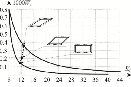
The following test example demonstrates the application of the form factor interpolation method for deformation analysis of elastic orthotropic plate. The plywood plate has form of parallelogram, as can be seen from 0 in center. The plate is subjected to the uniform distributed load, having intensity q = 10 kN/m2. Source data are the following: a = 1.5 m; b = 1 m; t = 0.02
m; α = 45о; K
f = 12.2565; A = 1.061 m2, Ex = 7000 MPa; Ey = 5500 MPa; Gxy= 800 MPa; νx =
0.07. It is required to find the value of maximum deflection for the plate.
Solution. In the first approximation, plywood can be considered an orthotropic material. The given plate can be obtained as a result of affine shift of a rectangular plate into rhombic. As can be seen from Fig.3 the maximum deflection value for the given plate locates between the maximum deflection curves for rectangular and rhombic plates. Parameters of rectangular plate are: a = 1.5 m; b = 0.707 m; Kf1 = 10.371; A1 = 1.061 m2; parameters of rhombic plate are: a = 1.5 m; α = 28.1о; K
f2 = 16.971; A2 = 1.061 m2. Here indexes “1” and “2” are related to the
parameters of the first and second reference plates. Values of maximum deflection (W0)1 = 1.861 mm; (W0)2 = 1.892 mm for reference plates can be obtained from expression (14). Substituting these reference solutions in the formula (9), we obtained the value W0 = 1.868 mm, which differs about 0.2% from results W0 = 1.865 mm, that was found with the finite element method at continuum-partition into 1000 shell finite elements.
Fig. 3. Diagram of 1000W0 – Kf for test example
Conclusions
Summarizing paper results, the following conclusions can be formulated:
of application of the form factor interpolation method has been presented. The results have been validated against values obtained by other methods.
2. Due to mathematical similarity of differential equations, which describe transverse bending problems, problems of free vibrations and stability, the proposed method can be extended to solve these problems.
Извод
Решавање
проблема
трансверзалног
савијања
еластичних
ортотропних
плоча техником интерполације фактора облика
V.I. Korobko1, A. V. Korobko1, S. Y. Savin1*, A. A. Chernyaev1
1 Orel State University, Komsomolskaya 95, 302026, Орел, Русија
имејл: [email protected]
*главни аутор
Резиме
У овом раду се разматра проблем трансверзалног савијања ортотропних плоча са кoмбинованим граничним условима. Техника интерполације фактора облика је коришћена
за срачунавање деформација. Добијени су аналитички изрази за површине максималног угиба. Ови изрази су коришћени при избору референтних решења. Дат је пример решења проблема трансверзалног савијања плоче облика паралелограма.
Кључне речи: ортотропне плоче, трансверзално савијање, фактор облика, однос савојне
крутости, комбиновани гранични услови, максимални угиб, метода интерполације фактора облика
References
Ambartsumyan S (1991). Theory of Anisotropic Plates: Strength, Stability and Vibration, Hemisphere Publishing, New York.
Bao G, Jiang W, Roberts J (1997). Analytic and finite element solutions for bending and buckling of orthotropic rectangular plates. International Journal of Solids and Structures, 14, 1797-1822.
Huu-Tai Thai, Seung-Eock Kim (2012). Analytical solution of a two variable refined plate theory for bending analysis of orthotropic Levy-type plates, International Journal of Mechanical Sciences, 1, 269-276.
Korobko A (1999). Geometricheskoe modelirovanie formy oblasti v dvumernykh zadachakh teorii uprugosti [Geometrical Modeling of Region Form in the Two-Dimensional Problems of Elasticity Theory], ASV Publishing, Moscow (in Russian).
Korobko V (1997). Isoperimetric Method in Structural Mechanics: Theory of the Isoperimetric Method, ASV Publishing, Moscow (in Russian).
Journal of the Serbian Society for Computational Mechanics / Vol. 10 / No. 2, 2016 17 Korobko V, Korobko A, Chernyaev A (2016). Isoperimetric properties of the torsion rigidity of
convex sections, Procedia Engineering, 150, 1648–1656.
Kurpa L, Rvachev V, Ventsel E (2003). The R-function method for the free vibration analysis of thin orthotropic plates of arbitrary shape. Journal of Sound and Vibration, 261, 109-122. Lowe P (1984). Isoperimetric inequalities in structural mechanics. The ninth Australian
Conference on the Mechanics of Structures and Materials, University of Sydney, Sydney, 147-151.
Lowe P, Allen J, Collins I (1994). Limit Analysis of Plates and Isoperimetric Inequalities, Philosophical Transactions of the Royal Society A: Physical, Mathematical and Engineering Sciences, 347, 113-137.
Mbakogu F, Pavlović M (2000). Bending of clamped orthotropic rectangular plates: a variational symbolic solution, Computers & Structures, 2, 117-128.
Polya G, Szego G (1951). Isoperimetric inequalities in mathematical physics, Princeton Univ. Press, Princeton.
Rui Li, Yang Zhong, Bin Tian, Yuemei Liu (2009). On the finite integral transform method for exact bending solutions of fully clamped orthotropic rectangular thin plates, Applied Mathematics Letters, 12, 1821-1827.