Vol. 3, Issue 6 (June. 2013), ||V3|| PP 37-43
Closed Loop Control of Non-Isolated Bidirectional Dc/Dc
Converter
Soumya Manoharan,
1A.Swarnalatha
2,
1, PG scholar, Francis Xavier Engg College, Tirunelveli. 2, Associate Professor , Francis Xavier Engg College, Tirunelveli.
Abstract: – In this project a bidirectional dc-dc converter using ZVS technique employs a coupled inductor is
implemented. In step-up mode, the coupled inductors are parallely charged and serially discharged to get a high output voltage gain. In step-down mode, the coupled inductors are serially charged and parallely discharged to get a low output voltage gain. Current system using ordinary switching techniques, so that the switching loss is very high. Therefore more heat will dissipated. In ZVS technique, heat loss is minimum. So we can increase the life span of switches. Moreover, we can increase the output voltage. The proposed converter aims to reduce the switching current. It has higher step-up and step-down voltage gains than the conventional bidirectional dc-dc converter. For the same electric conditions, the proposed converter’s and the conventional bidirectional converter’s efficiency, voltage gain, output voltage and switching current will differ.Here closed loop control is used.By using a PID controller,we can obtain a high output voltage and high gain by controlling the duty cycle of switches.
I. INTRODUCTION
A DC to DC converter is an electronic circuit which converts direct current from one voltage level to another. It is a type of power converter.DC to DC converter are used in portable electronic devices such as cellular phones and laptop computers,which are supplied from batteries primarly. Such electronic devices mostly contain several sub-circuits,that are different from that supplied by the battery or any external supply,may be higher or lower than the supply voltage. Moreover,the battery voltage decreases as its stored power is decreased.Switched DC-DC converters offer a method to increase voltage from a partially lowered battery voltage ,thereby save the space instead of using a no:of batteries.Most DC-DC converters will regulate the output. High efficiency LED power sources,belong to the type of DC-Dc converters,which regulates the current through the LEDs,and the charge pumps will double or triple the input voltage.
A bi d i r e ct i on a l DC - DC c on v er t er i s u sed f or d c - d c c on v er si on p r oc e ss. The power converter has two full bridge converters,one act as inverter and other as rectifier.This bi d i r e ct i on a l DC - DC c on v er t er is suitable for electrical vehicle applications. It has advantages of simple circuit with soft switching implementation(ZVS),without additional devices.It have high efficiency and simple control. This advantages make the converter applicable for low,medium and high power applications;mainly for auxillary power supply in fuel cell vehicles and power generation. It is used in applications where high power density,low cost,low weight and high reliability power converters are required. Mi cr o C on t r ol l er i s u se d t o cr ea t e p u l s es f or s wi t ch e s. I t t r i g g er , op er a t e a n d c on t r ol MO S FE T S d e vi c es. PWM technique is used to reduce the harmonics and noises in the circuit.
II. CLASSIFICATION
Most of the existing bi d i r ect i on a l DC - DC c on v er t er s has the basic circuit structure shown in Figure 1, which is fed by a current or voltage on one side. Based on the auxiliary energy storage and conduction period,the bi d i r e ct i on a l d c- d c c on v er t er ca n b e cl a ssi fi ed i n t o bu ck a n d b o o st c on v er t er s. T h e bu ck t yp e h a v e en er g y st or a g e p l a c ed on t h e h i g h vol t a g e wi t h l o w c on d u ct i on p er i o d , a n d t h e b o o st t yp e h a ve i t p l a c ed on t h e l o w v ol t a g e si d e wi t h h i gh con d u ct i on p er i o d .
It is classified into two types:
• Isolated DC/DC Bi d i r ect i on a l C on v er t er
• Non- Isolated DC/DC Bi d i r ect i on a l C on v er t er
a. Isolated Dc/Dcb i d i r ec t io n al Co nv e rt e r
i s ol a t i on p u r p o s es. I n d u ct a n c e i s p r o v i d ed b et w e en t wo c u r r en t so u r c es. Fu l l br i d g e, h a l f br i d g e or p u sh - p u l l ci r c u i t s a r e u s ed f or isolated bi d i r e ct i on a l d c- d c c on v er t er . Galvanic isolation between inverter and converter circuits,high output voltage gain,high power applications and additional safety are its advantages.
b. Non- Isolated Dc/Dc B i d i re c t io nal Co nv e rt e r
In Non- Isolated Bi d i r ect i on a l DC - DC C on v er t er t here is no transformer. Isolated Bi d i r e ct i on a l DC - DC C on v er t er i s u s ed f or g a l va n i c i s ol a t i on p u r p os e s. T h i s wi l l a d d a d d i t i on a l si z e, wei g h t a n d co st . S o t r a n sf or m er - l e ss t yp e i s p r e f f er e d . Non- Isolated Bi d i r e ct i on a l DC - DC C on ver t er i s u s ed i n h i g h p o wer , sp a c e cr a ft a p p l i ca t i on s a n d i n a p p l i ca t i on s wh er e l o w we i g h t a n d si z e i s r eq u i r ed . I t i s a c om b i n a t i on o f st ep - u p a n d st e p - d o wn st a g e s. I t h a s a n t i p a r a l l el l y c on n ect e d r ect i fi er a n d i n ver t er ci r cu i t s. I n m ot or d r i ve op er a t i on s, t h e st ep - u p st a g e i s u s ed i n cr ea s e ba t t er y v o l t a g e. St ep - d o wn st a g e i s u s ed t o br ea k cu r r en t in veh i cl e r eg en er a t i v e br e a k i n g .
Inorder to reduce the disadvantages of Isolated Bi d i r ect i o n a l DC - DC C on v er t er , h er e we a r e u si n g a Non - Isolated Bi d i r e ct i on a l DC - DC C on ve r t er .
III. A.STEP-UP MODE
ZVS technique is used to control the switches. Here S1 and S2 are the main switches and S3 is the auxillary switch.
Vl
..
.
.
L1
L2 S1
S2
S3
Vh
Figure.1 Conventional bidirectional dc-dc converter.
The inductance of the coupled inductors are same,because ther primary and secondary windings are same.
The mutual inductance is given by,
where k is the coupling coefficient of the coupled inductor. The voltages across L1 and L2 is:
The bidirectional converter has two modes of operations: continuous mode (CCM) and discontinuous mode(DCM).
a) CCM Operation
1) Firstly S1 and S2 are conducting and S3 is in OFF position. The supply from the low voltage side is passed to the coupled inductors. They get parallelly charged.Capacitor get charged towards the load.Here,the voltage across the two inductors are same and they may be equal to Vl.
The state-space method is given by,
The voltage gain can be calculated by the equation :
b) DCM Operation
1) Firstly S1 and S2 are conducting and S3 is in OFF position. Operation is similar to that of CCM mode. Current flowing through L1 and L2 are same.
2) Here,S1 and S2 is in OFF condition.S3 is conducting. The coupled inductors are seriesly charged. The low voltage supply will energises the capacitor and the load. The current through the two inductors will becomes zero.
3) There is a time interval in which S1 and S2 are continuing in OFF position and S3 is in ON mode. Now the energy in the two inductors becomes zero. So current also becomes zero. Capacitor will get discharged.
The current through the capacitor is :
Finally, the voltage gain is,
B. STEP DOWN MODE :
ZVS technique is used to control the switche S3. Switches S1 and S2 are not active here. The two modes of operation,CCM and DCM are explained below :
a) CCM Operation
1) Firstly S3 is conducting and S1 & S2 are
in OFF position. The supply from the high voltage side is passed to the coupled inductors,capacitors and the load. Inductors get serially charged. And the current across them are same.
2) S1 and S2 are conducting and S3 is in OFF position. Energy of the coupled inductors are discharged to the capacitor and load. The conductors are parallely connected. Voltage flowing through L1 and L2 are same.
The voltage gain can be calculated by the equation :
b) DCM Operation
3) There is a time interval in which S1 and S2 are continuing in ON position and S3 is in OFF mode. The energy stored in the coupled inductor is zero. Now the energy in the two inductors becomes zero. So current also becomes zero. Capacitor will get discharged towards the load.
Finally, the voltage gain is,
IV. ZVS TECHNIQUE
In the applications of bidirectional dc-dc converter,efficiency is the main parameter. Many soft switching techniques are used to improve the efficiency. ZVS means,the switch is turn ON only at zero voltage . By doing like this,the switching losses and power losses can be eliminated.ZVS can be applied in both forward and reverse directions without the help of an external device. By this we can reduce the no:of components,therby the size and cost of equipment get reduced.
Normal switching technique has high switching and heat loss. But ZVS has low heath loss, high output voltage and can increase the life span of switches. Switching current and frequency can also be reduced.
V. ADVANTAGES
• ZVS has low heat loss
• High output voltage
• Can increase the life span of switches
• Switching current and frequency can be reduced
IV CLOSED LOOP CONTROL
Vl
..
.
.
L1L2 S1
S2
S3
Vh
Closed loop controller
(PID)
Figure.2 Closed loop control of bidirectional dc-dc converter.
Closed loop control is more advantageous than open loop control. Output can be fed back to input. By doing like this,no energy get wasted during regenerative braking. Using closed loop control,we can control the duty cycle of the switches and there by we can obtain a high output voltage gain.
VI. PID CONTROLLER
Mainly there are three types of controllers used:
P controller
PI controller
PID controller
PID means Propotional Integral Differential controller. It have a very small error signal. And its settling time is also very small.By controlling the duty cycle of switches,PID controller will obtain a high output
voltage,high voltage gain and it helps to decrease the noise disturbances. Because of this advantages,here we are using a PID controller.
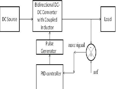
Figure 3 shows the block diagram of PID controller based bidirectional dc-dc converter. A dc supply is given to bidirectional dc-dc converter. Then output is given to load. This output is taken and get compared with a reference signal by using a comparator. Reference signal is a previously set value. The difference between the output signal and the reference signal is the error signal. This is then given as input for the PID controller. PID controller will control the duty cycle of the switches by using a pulse generator. And finally obtained a high output voltage.
Figure.3 Block diagram of bidirectional dc-dc converter.
VII. SIMULATION RESULT
Closed loop control for step up operation
Closed loop control is applied across the first switch and the auxillary switch for getting step up operation.From graph , it is seen that frequency is 50khz and we get an output voltage of 140V.
Figure.4 Closed loop control for step up operation
Closed loop control for step down operation
Figure.5 Closed loop control for step down operation.
ZVS technique for step up operation
ZVS technique is applied across the first switch and the auxillary switch for getting step up operation.From graph , it is seen that we get an output voltage of 52V.
Figure.6 ZVS technique for step up operation
ZVS technique for step down operation
VIII. CONCLUSION
In this paper a ZVS based bidirectional dc-dc converter is used. It has a very simple circuit diagram. The converter has The proposed converter has higher step-up and step down voltage gains and lower average value of the switch current than the conventional bidirectional boost/buck converter.And also by using the ZVS technique , we can reduce the heat loss and thereby can increase the life span of switches. ZVS reduces the switching current and frequency and a high output voltage is obtained the switching current and frequency and a high output voltage is obtained. Closed loop control is advantageous than open loop control.By using a PID controller,we can obtain a high output voltage and high gain by controlling the duty cycle of switches.
REFERENCE
[1] Kwan-Hwa Lui, Fred C .Y Lee, “Zero-Voltage Switching Technique in DC/DC Converters,” IEEE tran. on power electronics,vol.5,no.3.july 1990.
[2] J inrong. Qian , Issa. Batarseh , M.Ehsani , “Analysis and Design of a Clamp-mode Isolated Zero-Voltage Switching Boost Converter,” IEEE 1995.
[3] Praveen K.Jain, Wen Kang, Harry Soin and Youhao Xi, “ Analysis and Design Considerations of a Load and Line Independent Zero Voltage Switching Full Bridge DC/DC Converter Topology,” IEEE transactions on power electronics,vol.17.no.5 , Sep 2002.
[4] Luciano Schuch,Cassiano Rech, Helio Leaes Hey, Hilton Abilio Grundling, Humberto Pinheiro and Jose Renes Pinheiro, “Analysis and Design of a New High Efficiency Bidirectional Integrated ZVT PWM Converter for DC-Bus and Battery Bank Interface,” IEEE Transactions on industry applications, vol.42,September/October 2006.
[5] Zhiling Liao and Xinbo Ruan, “ A Novel Power Management Control Strategy for Stand-Alone Photovoltaic Power System,” IEEE 2009.
[6] Tanmoy Bhattacharya, V.Shriganesh Giri, K.Mathew and L.Umanand, “Multiphase Bidirectional Fltback Converter Topology for Hybrid Electric Vehicles,” IEEE Transactions on Industrial Electornics, vol.56,no.1,January 2009.
[7] F.Zhang and Y.Yan, “ Novel Forward-Flyback Hybrid Bidirectional DC-DC Converter,” IEEE Trans.Ind.Electron.,vol.56,no.5,pp.1578-1584,May 2009.
[8] G.Ma, W.Qu, G.Yu, Y.Liu, N.Liang, and W.Li, “A Zero Voltage Switching Bidirectional DC-DC Converter with State Analysis and Soft Switching-Oriented Design Consideration,” IEEE Tras.Ind.Electron.,vol.56,no.6,pp.2174-2184,June 2009.
[9] X.Zhu, X.Li, G.Shen, and D.Xu, “ Design of the Dynamic Power Compensation for PEMFC Disributed Power System,” IEEE Trans.Ind.Electro,., vol.57,no.6,pp.1935-1944,June 2010.
[10] Y.P.Hsieh, J.F.Chen, T.J.Liang, L.S.Yang, “ Analysis ad Implementation of a Novel Single-Switch High Step-up DC-DC Converter,” IET Power Electron.,2011,vol.5,Iss.1,pp.11-21 11 doi: 10.1049/iet-pel.2010.0279.
[11] A.Mirzaei, A.Jusoh, Z.Salam, E.Adib, H.Farzanehfard, “ A Novel Soft Switching Bidirectional Coupled Inductor Buck-Boost Converter for Battery Discharging-Charging” , IEEE 2011.