Neelakrishnan et al. World Journal of Engineering Research and Technology
HYBRID POWER SYSTEM FOR PSO TUNED LOAD FREQUENCY
CONTROL
G. Neelakrishnan*1, M. Kannan2 and D. Vinoth3 1,2,3
Department of Electrical and Electronics Engineering. 1,2,3
Muthayammal College of Engineering, Rasipuram.
Article Received on 24/09/2018 Article Revised on 14/10/2018 Article Accepted on 04/11/2018
ABSTRACT
This paper deals with the Particle Swarm Optimisation (PSO) tuned
Load Frequency Control (LFC) of single area power system, with
diversified power sources. The diversified generating units considered
for the purpose of LFC study are thermal, hydro and gas power plants.
Hybrid power system increases the reliability of the supply and instigates economic/feasible
system operation. System frequency gets affected due to real power changes, this is regulated
using Load Frequency Control (LFC). The hybrid interconnected power system with various
generating units imposes additional complexity in the tuning of controllers. Thus in this paper
PSO based tuning is imposed to obtain sophisticated control parameters for LFC of Hybrid
power system.
KEYWORDS: Load Frequency Control, Hybrid power system, Particle Swarm Optimisation, Tuning of PI controller.
INTRODUCTION
In the present circumstances power system operation and control has become more intricate
due to increase in the inclusion of numerous new electric utilities to meet the increasing
demand of electric power. In general, individual power stations cannot generate necessary
real power during a faulted condition or when there is a substantial increase in the load.
Whereas Hybrid Power Systems with various generation sources like thermal, hydro, gas etc.,
can meet different desired load scenarios, thereby ensuring consumer demands. Hybrid power
World Journal of Engineering Research and Technology
WJERT
www.wjert.org
SJIF Impact Factor: 5.218*Corresponding Author G. Neelakrishnan
Department of Electrical
and Electronics
system restricts unnecessarily tripping of generators owing to large disturbances, thus
enhancing system stability and reliability. Worldwide power grid has witnessed some
critical blackouts. In most of these cases, inadequate load frequency control is found to be the
major cause. Thereby, Load Frequency Control (LFC) plays a vital role in maintaining
synchronism among diversified multi-source generations.[1] LFC helps in adequate control of real power output from generating units in hybrid power systems when there is a change or
unanticipated occurrence of load perturbation.[2] LFC consists of two control loops, the primary loop performs pilot adjustment to frequency subsequent to the load disturbances and
allows the participating GUs to share loads depending on their individual speed regulation
constraints. The secondary loop is the ancillary control loop which does further adjustments
in the system to maintain its preset nominal frequency.
Particle Swarm Optimisation (PSO) is an effective optimisation methodology that has been
lucratively applied to numerous complex optimisation problems. It has the ability to avoid
tendency towards local minima by employing an adaptive memory system.[3-6] PSO is based on swarm intelligence and when compared to other such approaches it has the advantage of
uncomplicated implementation and there are few parameters to be preselected. Hence in this
paper PSO algorithm is used to tune the PI controllers of the various generating units in the
LFC of the Hybrid power system.
The remaining part of this paper is organized as follows: Section 2 describes the modelling of
single area LFC of Hybrid power system comprising of thermal, hydro and gas generating
units. In Section 3, the mathematical problem formulation for tuning the PI controllers and
subsequently the solution methodology using PSO algorithm are presented. In Section 4,
simulation results and analysis are presented. In Section 5, conclusions and further
discussions are drawn from the analysis and reported.
Modelling Of Single Area Load Frequency Control of Hybrid Power System A. Thermal generating station
In Thermal generating station the steam turbine converts energy of high pressure and high
temperature steam into kinetic energy which is, ultimately, converted into electrical energy
by the turbo-alternator. The speed governing mechanism controls the steam input to the
transfer function model of reheat turbine,[7-8] relating changes in turbine output power (∆Pmt) corresponding to change in gate valve position (∆Xt), is given by (1).
(1)
where, Kr is the steam turbine reheat gain, Tr is the steam turbine reheat time constant (in s) and Tt is the steam turbine time constant (in s). It may be noted that ∆Xt is the result of speed governor action which is given by (2).
(2)
where Rt is the speed regulation parameter (in Hz/p.u. MW), Tsg is the speed governor time constant (in s), ∆Ptref is the reference set power of thermal unit (in p.u. MW) and ∆F is the deviation in nominal frequency (in Hz).
B. Hydro Generating unit
Hydro turbine based prime mover converts the kinetic energy of water flow into mechanical
energy and, ultimately, it is converted into electrical energy using generator. Though speed
governing mechanism for both thermal and hydro turbine is based on speed droop
characteristics, Hydro turbine also requires transient droop compensation for stable speed
control performance. Transfer function model,[9-10] describing how the hydraulic turbine power output (∆Pmh) changes in response to a change in gate valve position (∆Xh) is given by
(3)
where Tw is the nominal starting time of water (in s). A linear approximation of the speed governor with transient droop in hydraulic turbine is given by (4)
(4)
Where Rg is the permanent speed droop (in Hz./p.u. MW), Tgh, Trs and Trh are the hydro turbine speed governor main servo time constant (in s), reset time constant (in s) and transient
C. Gas Turbine Generating unit
In general, Gas Turbine Generating Unit are multi-fuelled generating system consisting of
speed governor, valve positioner, fuel system and combustor in conjunction with associated
necessary control mechanism.
Transfer function model,[2] describing how the GT power output changes (∆Pmg) in response to a change in gate valve position (∆xg) and ∆F is given by (5)
(5)
Where T2 is the fuel time lag constant (in s) of the fuel system block and Dtur is the turbine damping (in p.u.).Expression for the fuel valve gate opening (with the maximum and the
minimum opening limit being FOVmax and FOVmin, respectively) is the function of the minimum of the two signals coming out of low value gate (LVG) and is given by (6)
(6)
where Rg is the speed regulation parameter (in Hz./p.u. MW), T1 is the fuel time lag constants (in s) of the fuel opening valve block, T3 is the load limiter time constant (in s) of the exhaust temperature block, ∆Pfsb is the output (in p.u.) from fuel system block having time constant T2 (in s), KT is temperature control loop gain and Lmax is the load limit. In this model, ∆Pgref is the reference set power for Gas Turbine Generating Unit.
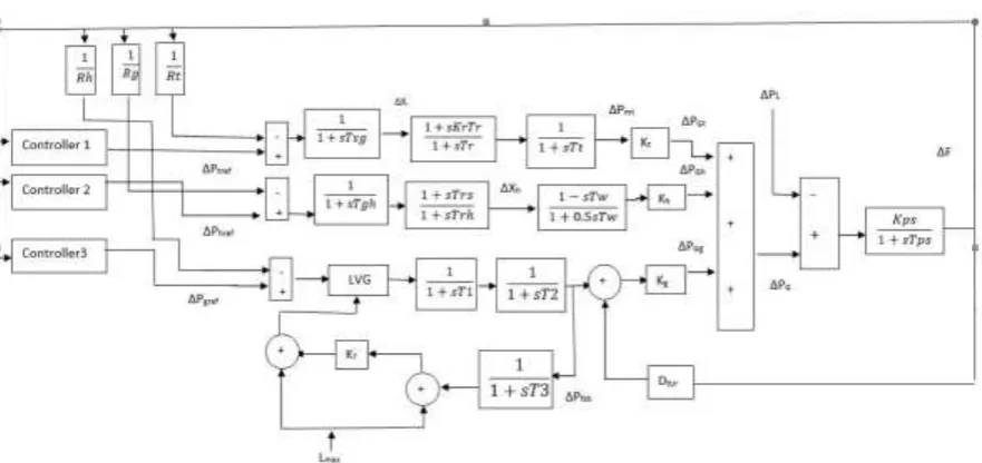
D. Modelling of single area hybrid power system
Transfer function model of the single-area hybrid power system for LFC study is developed
by the combination of thermal, Hydro and Gas Turbine Generating Units as presented in
Fig.1. In Fig.1., Kt, Kh and Kg represents participation factors from Thermal, Hydro and Gas Turbine Generating Unit, respectively.
Following a small change in load (∆PL) in p.u., the total change in net power generation ∆PG (p.u.) is given by (7), (8) and (9)
where Kt+Kg+Kh=1
(9)
where Kps is the power system gain and Tps is the power system time constant (in s).
Mathematical Problem Formulation for Tuning Pi Controller and Pso Based Solution Methodology
Mathematical problem formulation for tuning PI controller
The objective function termed as Figure of Demerit (FOD) is formulated for optimal
performance analysis of the single-area power system model. FOD for single-area with
multi-source power system model shown in Fig. 1, is defined by, (10)
Objective function: Minimum FOD
(10)
Where, tsim is the time duration of simulation (in s).
Subject to the constraints on control variables stated by (11) and (12)
(11)
(12)
PSO based solution Methodology
The problem stated in the above section regarding the tuning of PI controller for LFC of
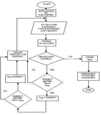
hybrid power system is solved using PSO based methodology. The flowchart shown in Fig.2,
Fig. 2: Flowchart for PSO algorithm.
The sequential steps involved in the PSO based tuning of PI controller in LFC of hybrid
power system are as follows
Step1. Random initialization of swarm consisting of initial position with control parameters
namely KP and KI of thermal, hydro and gas units within their feasible limits.
Step2. Each particles frequency deviation ∆f(t) is obtained using the transfer function model
developed under section II. The control parameters of each position are the input for the
controller in the Fig.1.
Step3. Evaluate the fitness of each particle using (10).
Step4. If the termination criterion is satisfied then store GBEST and stop the optimisation process.
Step6. If the LBEST present value is less than previous value then update position and velocity and proceed with Step 2.
Step7. After Step5 check GBEST, if the present value better than previous value then GBEST = present else update position and velocity and proceed with Step 2.
SIMULATION RESULTS AND ANALYSIS All The hybrid power system considered for the LFC
Analysis consist of thermal, hydro and gas generating units of rated capacity of 1000 MW,
600 MW and 400 MW respectively. The MVA based of the power system is considered as
100. All the parameter of the studied single-area power system configuration are included in
appendix. The range of the control parameters is chosen as 0.01 to 10. The simulation time
(tsim) is taken as 100s .The PSO parameters are as follows: Number of particles = 20; Max. iteration = 200: Acceleration factors = 1.1:Inertia weigh constant = 1.6. The simulation of the
LFC model is done using MATLAB/SIMULINK and the code for the proposed PSO is
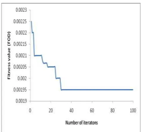
realized using MATLAB software. The convergence characteristics of PSO algorithm for PI
controller tuning of LFC is shown in Fig.3.
Fig. 3: Convergence characteristics of PSO algorithm for PI controller tuning of LFC. From Fig. 3, it is inferred that the PSO algorithm converges without any abrupt oscillations
thus the applicability of the proposed algorithm is ascertained. Under the action of PI
controller with 0.1 p.u.MW increase in load, PSO optimized controller gains for each
Fig. 4: Single area LFC model of Hybrid Power system.
Table I: PSO optimized controller gains of PI controller in LFC for hybrid power system
Generating unit KP KI FOD
TGU 5.999 1.1918
0.00195
HGU 0.0010 1.4290
GTGU 5.7516 1.9869
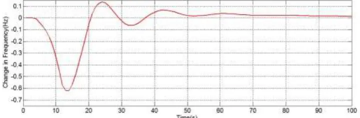
The change in frequency profile for the PSO tuned (Table 1) LFC of hybrid power system is
shown in Fig.4. From Fig. 4, it is inferred that due to PI controllers action the frequency
deviation settles to zero under steady state. Moreover it can be observed that the maximum
frequency deviation due to 0.1 p.u. MW increase in load is 0.59 Hz
.
Fig. 5: Change in frequency profile for the PSO tuned LFC of hybrid power system (multi-source system).
The change in frequency profile for the PSO tuned LFC of Thermal power system (excluding
Fig 6: Change in frequency profile for the PSO tuned LFC of Thermal power system (single source system)
On comparing Fig.4 and Fig.5. it is evident that the maximum frequency deviation is minimal
for hybrid power system.
CONCLUSIONS
The In this paper, LFC of single-area hybrid power system incorporating thermal ,hydro
and gas generating units has been presented. The LFC is comparatively analysed for the
hybrid system and isolated thermal system for an increase in load with PI controllers. The
gain(s) of these PI controllers are tuned using PSO based methodology. Results obtained
shows that performance of the PSO tuned PI controller is found to be suitable for stable
power system operation. In addition the comparative analysis of hybrid and isolated power
system reveals the superiority in the frequency control of hybrid power system.
Appendix
Parameters of single-area power system model
Rt = Rh = Rg = 2:4 Hz/p.u. MW, Tsg = 0:08 s, Tt = 0:3 s, Tr = 10 s, Kr = 0:3; Tw = 1 s, Trs
= 5 s, Trh = 28:75 s, Tgh = 0:2 s, T1 = 1:5 s, T2 = 1:5 s, T3 = 3 s, Lmax = 1, KT = 1,
FOVmin = _0:02, FOVmax = 1, Dtur = 0, Kps = 68:9566, Tps = 11:49 s, Kt = 0:543478, Kh
= 0:326084, Kg = 0:130438.
REFERENCES
1. P Kundur. “Power system stability and control,” 8th ed, New Delhi, TataMc-Graw Hill,
2009.
2. G. Shankar, V. Mukeerjee on “Quasi oppositional harmony search algorithm based
controller tuning for load frequency control of multi-source, multi-area power system”.
3. Yong Zhang, Dun-wei Gong, and Jian Cheng on “Multi-Objective Particle Swarm
Optimization Approach for Cost-Based Feature Selection in Classification,” IEEE Transl.
J. Magn, 2017; 14(1): 64-75.
4. Peng Hou, Weihao Hu, Mohsen Soltani, Zhe Chen. “Optimized Placement of wind
turbines in large-scale offshore Wind Farm Using Particle Swarm Optimization
Algorithm” IEEE transactions on sustainable energy, 2015; 6(4): 1272-1282.
5. SHU Dasong, HUANG Zhixiong, LI Junye and ZOU Xiaoyang, “Application of
Multi-agent Particle Swarm Algotithm in Distribution Network Reconfiguration”, Chinese
Journal of Electronics, 2016; 25(6) 1179-1185.
6. Chakkarapani Manickam , Guru Raghav Raman, Guru Praneesh Raman ,Saravana Ilango
Ganesan and Chilakapati Nagamani, “ A Hybrid Algorithm for tracking og GMPP Based
on P and O and PSO with Reduced Power Oscillation in String Inverters”, IEEE
Transactions on Industrial Informatics, 2016; 63(10): 6097-6106.
7. Asadur Rahman, Lalit Chandra Saikia,Nidul Sinha. “Load Frequency Control of
Hydro-thermal system under deregulated environment using biogeography based optimised
three-degree-of-freedom integral derivative controller”, The Institution of Engineering
and Technology, 9(15): 2284-2293.
8. Vijay P.Singh,Nand Kishor and Paulson Samuel, “Load Frequency Control with
Communication Topology changes in Smart Grid,”IEEE Transactions on Industrial
Informatics, October 2016; 12(5): 1943-1952.
9. Mohit Kumar Pandey, Mahesh Kumar Meena, Omveer Singh, Prashantjeet Tyagi.
“Load Frequency Control of Hydro and Nuclear Power System by PI and GA controller”,
International Journal of Scientific and Research Engineering and Technology, 2013;
2(6): 326-331.
10.Xiangjje Liu , Xiaobing Kong ,Kwang Y.Lee, “Distributed model predictive control for
load frequency control with dynamic fuzzy valve position modelling for hydro-thermal
power system”, The Institution of Engineering and Technology, 10(14): 1653-1664.
11.C.Nagarajan and M.Madheswaran - „Experimental verification and stability state space
analysis of CLL-T Series Parallel Resonant Converter‟ - Journal of ELECTRICAL
ENGINEERING, Dec.2012; 63(6): 365-372.
12.C.Nagarajan and M.Madheswaran – „Analysis and Implementation of LLC-T Series
Parallel Resonant Converter with Fuzzy controller‟- International Journal of Engineering
13.C.Nagarajan and M.Madheswaran - „Performance Analysis of LCL-T Resonant
Converter with Fuzzy/PID Using State Space Analysis‟- Springer, Electrical Engineering,
September 2011; 93(3): 167-178.
14.C.Nagarajan and M.Madheswaran - „Stability Analysis of Series Parallel Resonant
Converter with Fuzzy Logic Controller Using State Space Techniques‟- Taylor & Francis,
Electric Power Components and Systems, May 2011; 39(8): 780-793.
15.C.Nagarajan and M.Madheswaran - „DSP Based Fuzzy Controller for Series Parallel
Resonant converter‟- Springer, Frontiers of Electrical and Electronic Engineering, 7(4):
438-446.
16.C.Nagarajan and M.Madheswaran - „Experimental Study and steady state stability
analysis of CLL-T Series Parallel Resonant Converter with Fuzzy controller using State
Space Analysis‟- Iranian Journal of Electrical & Electronic Engineering, September 2012;
8(3): 259-267.
17.C.Nagarajan and M.Madheswaran, “Analysis and Simulation of LCL Series Resonant
Full Bridge Converter Using PWM Technique with Load Independent Operation” has
been presented in ICTES‟08, a IEEE / IET International Conference organized by
M.G.R.University, Chennai, Dec.2007; 1: 190-195.
18.R.Raja and C.Nagarajan, 2018, “Performance Analysis of LCL-T Filter Based 2 Stage
Single Phase Gird Connected Module with ANN Controller using PV Pane," Current
Signal Transduction Therapy, 2018; 13(2): 159-167.
19.C. Nagarajan, M.Madheswaran and D.Ramasubramanian- „Development of DSP based
Robust Control Method for General Resonant Converter Topologies using Transfer
Function Model‟- Acta Electrotechnica et Informatica Journal, 2013; 13(2): 18-31.
20.R.Srinivasan et.al “Analysis and design of series inverter based load reactive power
compensation” in the International Journal of Innovative Research in Science,
Engineering and Technology (IJIRSET), 2015; 4(6).
21.R.Srinivasan et.al “Load Reactive Power Compensation using series inverter” in the
International Journal of Applied Engineering Research (IJAER), ISSN 0973-4562, 2015;
10(9).
22.R.Srinivasan et.al “Unbalanced Load Correction using Active Filter” in the International
Journal of Applied Engineering Research (IJAER), ISSN 0973-4562, 2015; 10(9).
23.R.Srinivasan et.al “Design and Analysis of Active Filter based Unbalanced Load
Correction” in the International Journal of Innovative Research in Science, Engineering
24.R.Srinivasan et.al “A Cascaded Multilevel H- Bridge Inverter for Electric Vehicles with
Low Harmonic Distortion” in the International Journal of Scientific Engineering and
Technology (IJSET) ISSN: 2349-6495, 2014; 1(6).
25.R.Srinivasan, M.Kannan and G.Neelakrishnan “AC/DC SEPIC Converter for Non-Linear
Controller” in the IJAREEIE, Nov 2014; 3(11).
26.R.Srinivasan et.al “Analysis of Low Power Dual Dynamic Node Hybrid Flip-Flop” in the
International Journal of Advanced Engineering Research and Science (IJAERS), 2014;
1(6).
27.R.Srinivasan et.al “A Hybrid Text Classification Approach Using Knn and Svm” in the
International Journal of Advances Foundation and Research in Computer (IJAFRC),
ISSN: 2349-6495, 2014; 1(3).
28.R.Srinivasan and D.Vinoth “Protection of Wireless Sensor Network from Gang Injecting
False Data Attack” has been published in International Journal of Advanced Research in
Electrical, Electronics and Instrumentation Engineering (IJAREEIE), February 2014;
3(2): 7301-7311.
29.R.Srinivasan et.al “Probabilistic Based Rock Texture Classification” has been published
in International Journal of Advances in Engineering & Technology (IJAET), 2014; 6(6):
2439-2447.
30.R.Srinivasan, R.Vinoth and D.Kalidass “Remote Admittance & Demonstrate For Client
Control Mobile Computing” has been published in International Journal of Scientific
Engineering and Technology (IJSET), 2014; 3(1): 13-16.
31.R.Srinivasan, et.al “Characterization of Color and Texture Features from Retrieved
Images using CBIR” has been published in International Journal of Research in Advent
Technology (IJRAT), Dec 2013; 1(5): 61-67.
32.R.Srinivasan et.al “FPGA Implementation of Efficient Modified VLSI Architecture for
Multiplier” has been published in International Journals of latest research in Engineering
and Computing (IJLREC), Nov-Dec 2013; 1(2): 7-10.
33.R.Srinivasan et.al “Stability Analysis of ARM Based Control of Brushless DC Motors
Using Digital PWM Technique” has been published in International Journal of Advanced
Research in Electronics and Communication Engineering (IJARECE), Nov 2013; 2(11):