International Journal of Mechanical & Mechatronics Engineering IJMME-IJENS Vol:16 No:03 108
Stability And Dynamic Control Of Four In-Wheel
Motored Vehicle Using Fuzzy PID Controller
ABDUSSALAM Ali AHMED
Institute of Sciences and Engineering, Okan university, 34959 Akfırat-Tuzla, Istanbul, Turkey [email protected]
Başar Özkan
Mechanical Engineering Department, Okan university, 34959 Akfırat-Tuzla, Istanbul, Turkey Başar.Ö[email protected]
Abstract— The yaw rate and the body sideslip angle (BSA) of vehicle are the most important parameters to describe vehicle stability and performance. The main goal of this paper is to improve the stability of in-wheel motored vehicle, this will be done by construct Simulink model using Matlab includes 2DOF vehicle dynamics as a reference model, 4 four wheel drive nonlinear vehicle model, and the structure of the fuzzy PID controller. Compared to conventional PID controller, the fuzzy PID controller can regulate the proportional, integral, and derivative parameters and improve the responds of vehicle system. Many simulation results show the vehicle stability control system using fuzzy PID controller can improve the handling and stability of the vehicle.
Index Term-- Vehicle simulation, Fuzzy PID controller, Vehicle
stability, Yaw rate, Sideslip angle.
I. INTRODUCTION
Vehicle stability is referred as the ability that vehicle could run at the route desired by driver without sideslip, side skid and rollover [1]. The disturbance such as side wind and various road conditions could make the vehicle unstable in emergency brake situation. In such case, the driver couldn't respond quickly in short time, so it is necessary to develop the automatic control system of vehicle stability and handling. The new research shows that the control of sideslip angle and direct yaw moment control is an effective method to achieve good vehicle stability. The purpose of yaw moment control is to keep the actual yaw rate and vehicle sideslip angle catch up with desired ones. The yaw moment can be acquired by means of steering, differential brake and differential traction control to correct vehicle motion, and help drivers stabilize vehicle direction. Most vehicles make use of brake method to create direct yaw moment.
In the last few years many researchers studied how to improve vehicle handling and stability using nonlinear vehicle model. The vehicle model used in this work is a 4WD electric vehicle, only considering the planar motion: longitudinal, lateral, and yaw. And the vehicle is modeled as a rigid body with 3-DOF .The pitch and roll motions are ignored. Also other assumptions shall be made: road bank and slope angles are zero and suspension dynamic and air drag force are ignored. Figure 1 shows the vehicle diagram with planar motion. Based on our survey of research trends in this study, many researchers have worked about vehicle dynamics control, stability, handling, and passengers comfort. All works give very practical results for specific estimation parameters like
lateral acceleration, yaw rate and sideslip angle and they use different control strategies such as yaw torque control of electric vehicle stability using sliding mode control method [2, 3], vehicle stability control for electric vehicle based on control allocation [4], and using of PID controller and Linear Quadratic Control method to improve the lateral stability control for electric vehicle [5]. Also, H∞ control method used to achieve better longitudinal, lateral and vertical motions of full vehicle dynamics [6]. Another new work used a map-based control method to improve a vehicle’s lateral stability performance [7].
The main different between this work and the other is using of Fuzzy PID controller with planar vehicle model to improve stability, handling, and comfort. The proposed control architecture in this paper similar control architecture was used in [8] for the simulation of vehicle stability control with some changes in the controller.
II. VEHICLEDYNAMICMODELANDTIREMODEL
A. VEHICLE MODEL
Fig. 3 shows planar vehicle model (3-DOF vehicle
model) used in the paper
[9].
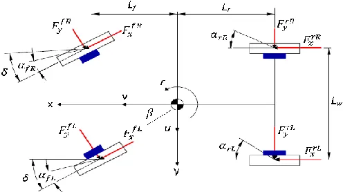
, , , , , , ,
force components
for front right, front left, rear right and rear left tire along x, y coordinates respectively; Lf ,Lr the distance of the center of gravity of the vehicle to front and rear axle; Lw distance
between leaf and right wheels; u, v longitudinal and lateral velocity , r yaw rate, δ is the front wheel steering angle.
The equations of motion of longitudinal, lateral, and yaw rate of the vehicle can be written as:
(
+
)
+
Where m is the vehicle mass, I is the moment of inertia of the vehicle about its yaw.
The individual tire slip angles are calculated using vehicle geometry and wheel vehicle velocity vectors. If the velocities at wheel ground contact points are known the tire slip angles can be easily derived geometrically and are given by:
Where αijis the tire slip angle at individual tires.
B. MODEL OF WHEEL DYNAMICS
A schematic of a modeled wheel is shown in Figure (2). The wheel has a moment of inertia J and an effective radius reff.
Torque T can be applied to the wheel and longitudinal tire force Fx is generated at the bottom of the wheel. The wheel
rotates with angular velocity ω and moves with a longitudinal velocity v. A summation of the moments about the axis of rotation of the wheel generates the dynamical equation shown in following equation:
Fig. 2. Wheel Schematic Diagram
C. TIRE MODEL
At extreme driving condition, the tire may run at non-linear religion. This study uses Dugoff’s tire model which provides for calculation of forces under combined lateral and longitudinal tire force generation. The longitudinal and lateral force of tire were expressed as [11]:
where C1 is the longitudinal tire stiffness,C2 is the cornering
stiffness of the tire and λ is given by
And
if λ˂1
if λ≥1
Fz is the vertical force on the tire, μ is the tire-road friction
coefficient while σx is the longitudinal slip ratio of the tire
which can be defined in the case of accelerating as:
D. 2DOF DYNANICS MODEL
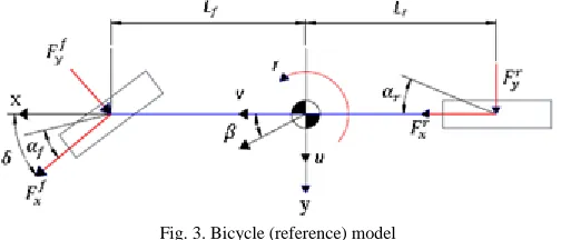
In vehicle dynamic studies, the reference vehicle model as shown in Figure (3) is prominently used for yaw stability control analysis and controller design. This model is linearized from the nonlinear vehicle model based on the some assumptions: Tires forces operate in the linear region, The vehicle moves on flat road (planar motion), and Left and right wheels at the front and rear axle are lumped in single wheel at the center line of the vehicle.
Fig. 3. Bicycle (reference) model
International Journal of Mechanical & Mechatronics Engineering IJMME-IJENS Vol:16 No:03 110
where Caf and Carare the cornering stiffness for each front and
rear tire respectively, the lengths Lf and Lr refer to the
longitudinal distance from the c.g. to the front wheels, longitudinal distance from the c.g. to the rear wheels, m is total mass of vehicle, v is longitudinal velocity of the vehicle and δ is the front steering wheel angle.
III. CONTROLSTRATEGY
In this study, the Fuzzy PID Controller is designed to improve EV yaw stability. The fuzzy PID controller can be decomposed into the equivalent proportional control, integral control and the derivative control components. we design a control system which includes three parts: the reference vehicle model (Bicycle model), planar vehicle model( Actual vehicle), and the fuzzy PID controller. The structure of vehicle model with controller is given in Figure (4).
Depending on𝛿which can be gained by the driver action and v, the desired vehicle’s sideslip angle 𝛽𝑑and desired yaw rate r𝑑 can be calculated through the reference model. The PID controller is applied widely, because it possesses the virtues such as the simple structure , better adaptability and faster response time. Regulating the parameters of the PID is the fussy task by manual work, while regulating parameter by fuzzy controller is very convenient. The sideslip angle 𝛽 is compared with desired sideslip 𝛽𝑑 and the yaw rate r is compared with desired yaw rate r𝑑, and then the sideslip angle error B and its rate of change EC are calculated. The fuzzy control is implemented as follow: the input variables, i.e., sideslip angle error E and its rate of change EC, are fuzzificated firstly, and then the output variables, the direct yaw moment Mz. The fuzzification is the process of
transforming fact variables to corresponding fuzzy variables according to selected member functions.
Fig. 4. The structure of vehicle model with controller
IV. SIMULATIONRESULTS
In this paper, the vehicle parameters used are given in the table below (9).
Table I
The Main Parameters of Vehicle
Symbol Unit Value
m Kg 1993
I Kgm2 2765
Lf m 1.402
Lr m 1.646
Lw m 1.6
reff m 0.365
J Kgm2 4.07
μ --- 1.0
C1 N/rad 52526
C2 N/rad 29000
g m/s2 9.81
Figure 5-Figure 8 present the selected results of vehicle model with and without control. Figure 5 and figure 6 present the longitudinal velocity and lateral acceleration of the vehicle while, figure 7 shows Comparison between the vehicle yaw rate with and without control and figure 8 present the Comparison between Side slip angle with and without control.It's obvious that, using of Fuzzy PID controller improved the vehicle stability performance.
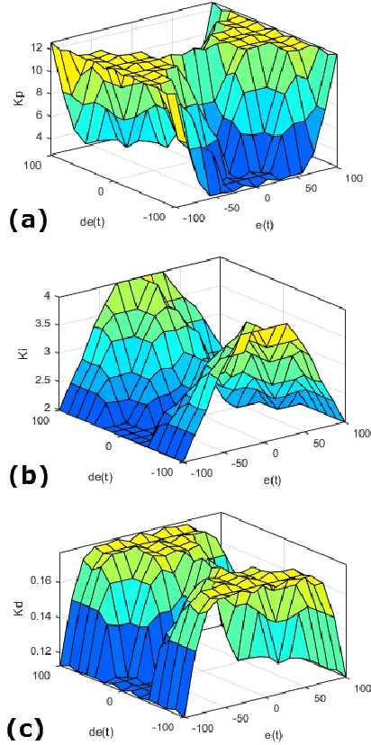
Figure 9 shows the input and output relations in the form of Cartesian rule surfaces.
Fig. 6. Comparison between Lateral acceleration with and without control
Fig. 7. Comparison between yaw rate with and without control
Fig. 8. Comparison between Side slip angle with and without control
Fig. 9. Input and output relations in the form of Cartesian rule surfaces for P, I, and D parameters. (a) P parameter; (b) I parameter; (c) D parameter
V. CONCLUSION
Aiming at improving in-wheel-motored vehicle stability, the simulink model of the vehicle is constructed with Fuzzy PID controller to ensure and improve the vehicle stability in this paper. The results and plots show a significant difference between the vehicle performance in the case of without control and the vehicle stability and performance in the case of using Fuzzy PID controller. It is found that, the lateral acceleration, yaw rate, and side-slip angle improved significantly. Therefore vehicle stability control system using fuzzy PID controller can enhance the performance and stability of vehicle.
REFERENCES
International Journal of Mechanical & Mechatronics Engineering IJMME-IJENS Vol:16 No:03 112 Transactions Fundamentals, Vol. E85-A, No.4, 2002, pp. 903-908.
[2] Hongtian Zhang, Jinzhu Zhang,Yaw Torque Control of Electric Vehicle Stability, IEEE 6th 2012.International Conference on
Information and Automation for Sustainability (ICIAfS), 2012. [3] Zhang Jinzhu, Zhang Hongtian, Vehicle stability control system based
on direct measurement of body sideslip angle, 2nd International Conference on Power Electronics and Intelligent Transportation System,2009.
[4] Li Feiqiang, Wang Jun, Liu Zhaodu, On the Vehicle Stability Control for Electric Vehicle Based on Control Allocation, IEEE Vehicle Power and Propulsion Conference (VPPC), September 3-5, 2008, Harbin, China.
[5] Işılay Yoğurtcu Selim Solmaz, S. Cağlar Başlamışlı, Lateral Stability
Control Based on Active Motor Torque Control for Electric and Hybrid Vehicles, IEEE European Modeling Symposium,2015. [6] S. Fergani,L. Menhour,O. Sename,L. Dugard,B. D'Andrea Novel, Full
vehicle dynamics control based on LPV/H∞ and atness approaches, 2014 European Control Conference (ECC), June 24-27, 2014. Strasbourg, France.
[7] Moon-Young Yoon, Seung-Hwan Baek, Kwang-Suk Boo, Heung-Seob Kim, Map-based control method for vehicle stability enhancement, J. Cent. South Univ, 22: pp. 114−120, 2015.
[8] You De Li, Wei Liu, Jing Li, Zhi Min Ma and Jia Cai Zhang,
Simulation of Vehicle Stability Control System Using Fuzzy PI Control Method, IEEE International Conference on Vehicular Electronics and Safety, 2005.
[9] Arjon Turnip, Hanif Fakhrurroja,Estimation of the Wheel-Ground Contacttire Forces using Extended Kalman Filter, International Journal of Instrumentation Science, 2(2), pp. 34-40, 2013.
[10] Siqi Zhang,Shuwen Zhou, Jun Sun, Vehicle Dynamics Control Based on Sliding Mode Control Technology, IEEE Control and Decision Conference,CCDC 09. 2009,Chinese