Implementation Of Automatic Wiper Speed
Control And Headlight Modes Control Systems
Using Fuzzy Logic
ThetKoKo, ZawMyoTun, Hla Myo TunAbstract: This research paper describes the design and simulation of the automatic wiper speed and headlight modes controllers using fuzzy logic. This proposed system consists of a fuzzy logic controller to control a car‘s wiper speed and headlight modes. The automatic wiper system detects the rain and its intensity. And, according to the rain intensity, the wiper speed is automatically controlled. Headlight modes automatically changes either from low beam mode to high beam mode or form high beam mode to low beam mode depending on the light intensity from the other vehicle coming from the opposite direction. The system comprises of PIC, impedance sensor, piezoelectric vibration sensor, LDR, headlamps and a DC motor to accurate the windshield wiper. Piezoelectric sensor is used to detect the rain intensity which is based on the piezoelectric effect. MATLAB software is used to achieve the designed goal.
Keywords: Fuzzy Logic, Impedance Sensor, Piezoelectric Sensor, Piezoelectric Effect
————————————————————
I
. INTRODUCTION
A driver‘s safety and comfort level is the essential facts in manufacturing modern vehicle of automobile industry. However, in modern days, the accidents are most common in commercial vehicles. These accidents are caused due to human errors, road designs, poor visions and physical impairments of vehicle. Among them, one of the most traffic accidents is due to the poor visions, and it gives a distraction on the main task of driving. In bad weather conditions such as heavy rain, snow, fog and so on, the driver cannot see the front view well due to the rain drops, fog and snow. At that time, wiper is an essential component to wipe rain drops or any debris from the vehicle‘s windscreen. And, the headlight is a very useful device during night travel. But, when the drivers use the high bright beam, it causes a discomfort to the person travelling from the opposite directions. When this beam falls on a person, it glares him for a certain amount of time because our eyes are exposed to a very bright light source of around 10000 lumens [5]. When he uses the high intense beam in heavy rain condition, the light will reflect to him. And then, he can also get the glare. As a result, he can undergo road accidents. To avoid this problem, the drivers must change the high beam to low beam mode. But, the wiper actuation and the headlight modes switch have to be controlled by the driver himself. So, the drivers cannot focus on their primary task of driving. So, this could lead to car accidents on our roads.
II
. SYSTEM DESCRIPTION
Fig.1 Block Diagram of the Proposed System
The overall system configuration is shown in figure 1. There are two main sections in this system: (1) an automatic wiper speed control system, and (2) an automatic headlight modes control system. In the wiper system, an impedance sensor is used to detect whether it is raining or not. To sense the rain intensity, a piezoelectric vibration sensor is used. This sensor is based on the piezoelectric effect. According to the signals getting from these two sensors, the controller decides the raining condition, and it drives the wiper at a low speed or at a high speed depending on the rain intensity. The headlight modes control system will operate depending on the rain condition and the light intensity from the other vehicles coming from the opposite direction. For this system, LDR is used to sense the light intensity. This system automatically switches the high beam mode into low beam to reduce the glare effect by sensing the approaching vehicle. Therefore, these two systems also eliminates the requirement of manual control by the driver which is not done at all times
A.Piezoelectric Sensor
It is a device that measures the pressure, acceleration, strain or force by using piezoelectric effect. And, it convert them to and electrical charge. When pressure (stress) is applied to a piezoelectric material, it vibrates and an AC voltage is produced. This effect is reversible. When a voltage is applied across the two sides of a piezoelectric material. This effect called ―Piezoelectric effect‖.
The generated voltage from a piezoelectric material can be calculated from the following equation.
V = Sv×P × D
Where V = Piezoelectric generated voltage (Volts)
Sv = Voltage sensitivity of the material (Volt *meters / Newton)
P = Pressure (N/m2)
D = thickness of material (meters)
Voltage sensitivity values are provided with the material when received from the manufacturer. Different materials and different geometry cuts give different sensitivities.
+
-Vout
VCC
To one of AN Pins
of Microcontroller
Piezoelectric
Sensor
Fig. 3 Vibration Sensing Circuit
Fig. 3 is the vibration sensing circuit. It is uses as a rain intensity sensing one by using the piezoelectric effect. Depending on the rain intensity, there is a different voltage drop on the resistor. For example, due to the heavy rain, the sensor will vibrate more and there is a more voltage drop on the resistor.For testing this circuit, the water from the tap is poured on the sensor by opening the tap instead of the rain intensity. Then, there is a voltage drop on the resistor, and these voltages are recorded.
Table 1. Voltages Generated by the resistor
B.LDR
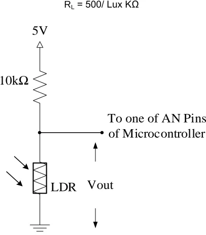
It is a device that can detect the light. Its resistance varies according to the amount of light that falls on it. When the light level is low the resistance of the LDR is high. The relationship between the resistance RLDR and the light intensity Lux for a typical LDR is
RL = 500/ Lux KΩ
10kΩ
LDR Vout
To one of AN Pins
of Microcontroller
5V
Fig. 4 Light Intensity Sensing Circuit
With the LDR connected to 5V through a 10KΩ resistor, the output voltage of the LDR is
Vout = 5×RL/ (RL+ 10)
Reworking the equation, the light intensity is obtained. Lux = (2500/Vout – 500)/ 10
III
. DESIGN PROCEDURE
In this paper, a fuzzy control algorithm is used to control the wiper speed depending on the rain intensity, and to change the headlight modes according to the light intensity from the other vehicles coming from the opposite direction. A fuzzy controller consists of three parts: Fuzzification, Fuzzy Logic Rule Base, and De-fuzzification.
Fuzzification: Converting the physical values of the current process signal, the error signal.
Rule-Base: A group of rules may use several variables both in the condition and the conclusion of the rules.
De-fuzzification: Converting all the fuzzy terms created by the rule base of the controller to crisp terms (numerical values).
A.Fuzzifier
Wiper Speed Control System
Fig. 6 shows the membership functions of the fuzzy input and output variables for the wiper speed. The membership functions for the raining are defined as No Rain and Raining while those for the rain intensity are defined as Drizzle, Raining and Heavy in fig. 6 and 7 respectively. And, the membership functions for the wiper speed are defined as Off, Low and High in fig. 8.Raining and Rain Intensity are measured in Volts. Table.1 shows the fuzzy logic rule base for the wiper speed control system.
Rain Intensity
No Rain (tap is closed)
Raining ( tap is opened little)
Heavy Rain (tap is opened more)
Voltage drop
Fig. 5 FIS Editor of Fuzzy Logic Controller for Wiper Speed Control
Fig. 6 Membership Functions of FLC for Raining
Fig. 7 Membership Function of FLC for Rain Intensity
Fig.8 Membership Function of FLC for Wiper
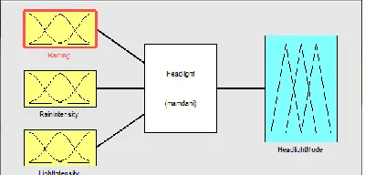
Headlight Modes Control System
In this system, the system fuzzy sets S (Satisfactory), JA (Just Acceptable) and UB (Unbearable) are assigned to the light intensity. And, the linguistic variables for the headlight modes are defined as LBM (Low Beam Mode) an HBM (High Beam Mode). Light Intensity is also measured in Lumens. The rule matrix representation for this system is shown in table 2.
Fig. 9 FIC Editor of Fuzzy Logic Controller for Headlight Modes Control System
Fig. 10 Membership Function of FLC for Light Intensity
Fig. 11 Membership Function of FLC for Headlight Modes
B.Rule Base
Table 2. Rule Base for Wiper Speed
Raining/ Rain
Intensity Drizzle Raining Heavy
No Rain Off Off Off
Raining Low Low High
Table. 3 Rule Base for Headlight Modes
NO. INPUTS OUTPUTS
IF (Raining)
IF(Rain Intensity)
IF(Light Intensity)
THEN(Headlight Modes)
1 No Rain Drizzle S HBM
2 No Rain Drizzle JA HBM
3 No Rain Drizzle UB LBM
4 No Rain Raining S HBM
5 No Rain Raining JA HBM
6 No Rain Raining UB LBM
7 No Rain Heavy S HBM
9 No Rain Heavy UB LBM
10 Raining Drizzle S HBM
11 Raining Drizzle JA HBM
12 Raining Drizzle UB LBM
13 Raining Raining S HBM
14 Raining Raining JA LBM
15 Raining Raining UB LBM
16 Raining Heavy S LBM
17 Raining Heavy JA LBM
18 Raining Heavy UB LBM
C.Fuzzification
Select two input variables of fuzzification process from the wiper speed control system to show how fuzzification is done in both the two systems.
FUZZIFICATION
Raining
Rain Intensity
f[0]
f[1]
f[2]
Fig. 12 Fuzzifier Block
Table 4. Result of Fuzzification
Input
Variables Values
Region
Selection
Fuzzy Set
Calculation
Raining x =
4.01 0.25< x <5
f0 =
(5-4.01)/(5-2.625) = 0.42
Rain
Intensity
x =
0.11
0.1< x <
0.18
f1 =
(0.12-0.11)/(0.12-0.06) =
0.17
f2 =
(0.11-0.1)/(0.14-0.1) = 0.25
D.Inference Engine
The inference engine accepts three inputs from the fuzzification process, and involves two AND operators. It is used to select minimum input value for the output. To get the output (R), the max-min composition is used.
R0 = f0 ^ f1 = 0.17 R1 = f0 ^ f2 = 0.25
R0
R1
MIN
AND
MIN
AND
F U Z Z I F I E Rf0
f1
f2
INFERENCE ENGINE
Fig. 13 Block Diagram of Inference Engine
E. Rule Selector
Two crisp values of raining and rain intensity accepted by the rule selector. This gives singleton values of output functions under algorithm rules applied on the design model. To find the corresponding singleton values (S0 and S1), two values are listed in table 5.
Table 5. Illustration of Rules for the Applied Modes
Rule No
Inputs
Singleton Values of
Outputs Singleton Values Raining Rain
Intensity
Wiper Motor Speed
1 Raining Drizzle Low = 5 S0
2 Raining Raining Low = 5 S1
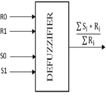
F. Defuzzification
After estimating its input, the defuzzification process provides the crisp value outputs [6]. Two values of R0, R1 from the outputs of inference engine and two values of S0, S1 from the rule selector are inputs of defuzzifier. Defuzzifeir uses the center of gravity (COG) is used to estimate the crisp value output.
Fig. 14 Rule Base
IV. RESULTS AND DISCUSSION
The design values for two outputs is shown in fig. 16. According to the results of inference engine:
∑ Ri = R0+R1 = 0.17+0.25 = 0.42
Table 6. Design Value for Wiper Speed
i Ri Si Ri*Si
0 0.17 5 0.85
1 0.25 5 1.25
∑ Si*Ri = 2.1
∑ Si*Ri/∑ Ri = 2.1/0.42 = 5
V. SIMULATION RESULT OF FUZZY LOGIC
CONTROLLER
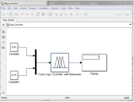
The results of the simulation of fuzzy logic based wiper speed control and headlight modes control are shown is fig. 12 and 13 respectively. For the wiper speed control system, the two FLC inputs Raining and Rain Intensity are 4.1 and o.11 respectively. So, it is in both a drizzle and raining conditions. Therefore, the FLC output, Wiper Speed, is 5. It means that the controller drives the wiper at a low speed.
Fig. 16 Rule Viewer of FLC for the Wiper Speed Control System
For the headlight modes control system, Raining is defined 2.5, and Rain Intensity is defined 0.15, and Light Intensity is defined 6000. So, this is a raining condition and the light intensity is just acceptable. Then, the FLC output is 1. So, the controller automatically switches from high beam modes to low beam mode.
Fig. 17 Rule Viewer of FLC for the Headlight Modes Control System
Table 7. Comparison of calculated and simulated results.
Result Wiper Speed
Design Value 5
MATLAB Simulation 5
% error 0
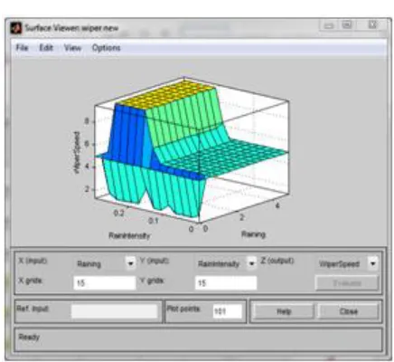
The surface viewer of FLC for simulation results are shown in fig. 18.
(a)
Fig. 18 Surface Viewer (a) Wiper Speed Control System;
(b) Headlight Modes Control System
Fig. 19 Checking with MATLAB Box (a) Wiper Speed Control System; (b) Headlight Modes Control System
(b)
VI. CONCLUSION
The system will operate automatically without manual action of human beings. The drives do not need to focus on wiper speed, intensity of headlamp and collision. The system will give a new dimension of comfort and aid to the drivers who work during rains at night and traffic prone areas. So, the drivers can more concentrate on the basic ABC(accelerator, brake and clutch) of driving. Therefore, this system can provide the safety to drivers. So, this system is very useful for drivers, and improves drivers‘ comfort level. The whole system is based on the fuzzy logic control. FIS editor of Matlab fuzzy logic controller is used to obtain the rule viewer and surface viewer.
REFERENCES
[1] Mr. Anil G. Bansode, Prof.S.O. Rajankar and Dr. M. G.Ghatule, ―Design and development of smart automatic windshield wiper system: fuzzy logic approach‖, International Journal of Engineering and Science, Vol.1, Issue 1, PP 14- 20, August 2012
[2] Mrs. Niraimathi.S, Dr. Arthanairee A.M, Mr. M.Sivaakumar, ―A Software and a Hardware Interface for Reducing the Intensity Uncertainties
Emitted by Vehicular Headlight on Highways‖, International Journal of Innovative Technology and Creative Engineering, Vol. 1, No 11, November 2011.
[3] Shantanu Dharmadhikari, NaeemTamboli, NileshGawali, Prof. N. N. Lokhande, ―Automatic Wiper System‖, International Journal of Computer Technology and Electronics Engineering, vol.4, Issue 2, pp.15-18, April 2014.
[4] Surface vehicle recommended practice, ‗Passenger Car Windshield Wiper system‘
[5] A.S.MAsaduzzaman, Mohammad Mahmudul Islam, Shuva Paul, MdFarhatAlam, MdMashuker Rahman‖,Automatic High Beam Controller for Vehicles‖, International Journal of Scientific & Engineering Research, vol. 4, Issue3, March-2013.
[6] Tarun Kumar Das, Yudhajit Das, ― Design of a Room Temperature and Humidity Controller Using Fuzzy Logic‖, American Journal of Engineering Research, Vol. 2, Issue 11, PP 86-97.