DEVELOPMENT OF A SOFTWARE APPLICATION FOR DESIGN AND 3D
MODELING OF A CONTROL ROD FOR A HYDRAULIC RECOIL BRAKE
Assoc. Prof. Ing. Ganev V. PhD.*, M.Sc. Ing. Dimitrova Ya.**, M.Sc. Ing. Antonov S.***
Faculty of “Artillery, air defense and CIS” – National Military University “Vasil Levski”, Veliko Tarnovo, the Bulgarian Republic
* [email protected], ** [email protected], *** [email protected]
Abstract: The design of complex armament details is a challenging process that requires great amount of time and data collected from ballistic calculation of the artillery tube. The developed software product that calculates the recoil brake’s piston rod replaces the large amount of computational work required, reduces the probability of calculation errors and enables the designer to focus his creative thinking into the combination of different materials and construction dimensions. The ability to export the calculated piston rod profile afterwards allows for easy transfer of the information required into a 3D virtual reality and the use of 3D modeling for the construction of the piston rod and the recoil braking device.
Keywords: HYDRAULIC RECOIL MECHANISM, HYDRAULIC RECOIL BRAKE, RECOIL-ROD.
1. Introduction
The hydraulic recoil brake serves to stop the movement of the recoil receiving parts after firing and functions as a kinetic energy converter, converting the recoil energy to thermal energy that heats up the mechanism’s elements and the brake fluids inside.
It’s working principle is that during recoil the liquid in cylinder under the influence of the pressure created by the movement of the recoil parts, passes with a high speed through specially created openings in the recoil brake. As a result of this transition and the resistance created by this action, the resisting force that stops the recoiling parts is created.
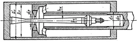
Fig. 1 Hydraulic recoil brake.
Дт–internal diameter of the cylinder of the recoil brake; Дт' –outer diameter of the cylinder of the recoil brake; dт– outer diameter of the piston rod; dн– inner diameter of the piston rod; dp–diameter of the piston’s throttling ring; δx– current diameter of the control rod; hx – current depth of the grooves on the inner surface of the piston rod.
The control rod type recoil brake consists of a circular cross-section but a variable diameter (control rod) that regulates the dimensions of the fluid drainage holes. The control rod diameter δх is calculated so that the braking resistance complies with the required laws physics for its change during the recoil movement.
After a comparative analysis of the software designed to compute complex mathematical tasks and output quick and accurate results and CAD / CAM / CAE systems suitable for design of the control rod model, the following program products were selected:
- MatLab - for creating an application using the embedded programming language, allowing calculation and visualization of the construction dimensions of the recoil cylinder. The application is flexible and adaptive, thanks to the built-in high-level programming language. The system can be tailored to the requirements of each user through programs developed by the user himself.
- SolidWorks - for 3D control rod modeling for enabling the braking of the recoiling parts during the recoil in the artillery systems. Allows easy products testing and preparation of the technical documentation and visualization of the forthcoming operations for making the desired detail of the machine.
2. Research
2.1. Purpose: Creating an application for modeling the control rod profile and 3D model of the recoil-rod.
2.2. Tasks:
-creating an application for profile modeling of the recoiling-rod of the recoil cylinder.
- creating a 3D recoil-rod model.
3. Description of the user application for designing
the profile of the recoil-rod of the recoil hydraulic
brake.
The commercial application for calculation of the control rod of the hydraulic recoil brake is developed on MatLab version 2017b. The program is supported by wide range of operating systems
Windows, MAX OS and Linux.
To view the exported data in an Excel spreadsheet a Microsoft Office installation is required.
Design by CSV (Comma-Separate Values) requires the Premium version of SolidWorks (2015-2018) installed.
For the design of the recoil brake it is necessary that a large volume of calculations including the estimate of the free recoil and actual recoil forces and calculations for the recoil brake and recuperator.
To make the calculations, input data obtained from the ballistic calculation of the body is used: d – system caliber; 𝑝𝑚𝑎𝑥 – maximum pressure ; 𝑝𝑔 – barrel pressure ; 𝑉𝑚– speed of the projectile at the moment of maximal internal pressure; 𝑉𝑔= 𝑉0– speed of the projectile when leaving the barrel; 𝑙𝑚 – the relative path of the projectile in the barrel bore at maximum pressure; 𝑙𝑔 – relative route of the projectile at the time of exit; 𝑡𝑚 – time until the maximum pressure; 𝑡𝑔 – time until the projectile exits the barrel; 𝑀0 – mass of the recoiling parts ; 𝑚 – projectile mass; 𝜇 – mass of the powder charge; 𝜑𝑚𝑎𝑥 – highest vertical angle; 𝜑пр – angle of stability; 𝜉 – efficiency coefficient of the recoil brake (if present); 𝑒 – eccentricity of the center of mass of the recoil parts relative to the oscillating line; 𝑀Б – mass when deployed; 𝐷00 – force of weight 𝑄Б when 𝜑 = 0; 𝐻 – high of the firing line; 𝑁𝑝′ – reaction to the towing hook.
Fig. 2 Starting the program.
Pressing the input key on the keyboard (Enter) opens a window where the input data is filled in (Figure 3).
Fig. 3 Window for input data.
Once all the data has been filled in, it is necessary to click on the "Save input data" button. Then the "Continue to calculating the free recoil” button appears (Figure 4).
Fig. 4 Button “Continue to calculating the free recoil”.
If any input data is not filled in or if it is filled in with a negative character the application warns that there is a missed or erroneous field filling it with a red color and a blank "Error" field appears signaling where the mistake is (Figure 5).
Fig. 5 Window “Error”.
Using the "Exit" button, located at the bottom left corner of the window, closes the application.
Once all the input data has been filled in and the button for calculating the forces of the free recoil is pressed the application opens the next window "Calculate the free recoil" (Figure 6).
The initial view of the window contains a panel called “First Period” which contains the “Calculate” button and several blank information fields. In the lower left corner of the window the "Home" button is located where the initial fill-in input window can be opened and with that close the current "Free recoil calculation" window.
Fig. 6 Calculation of the free recoil.
When the “Calculate” button is clicked the application fills the blank information fields and at the same time opens two new panels and a button (Figure 7) with the names:
Panel “Second period” –Contains additional information on free recoil calculation as well as a “Calculate” button whit which a command is provided that fills the information fields.
Panel “Information” –contains additional user information.
Button “Calculate W and L” – continues the required calculations.
Fig. 7 New panels.
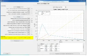
When the “Calculate W and L” button is pressed the program opens and fills up the original table for the calculation of the recoil brake then opens the graph showing the change of parameters and the "Continue to the actual recoil calculations" button (Figure 8).
Fig. 8 Full vision of the window “Calculations of the free recoil”.
From the drop-down menu above the diagram are selected the different graphs that are displayed (Figure 9).
Fig. 9 Drop-down menu.
Pressing the scroll button in order to proceed to calculate the actual recoil opens the "Calculate the actual recoil" window (Figure 10).
Fig. 10 Window “Calculation of the actual recoil”.
When pressing the calculation button on the Ro range the “Calculations for first and second period” panel opens. The difference from the previous panels is the white field in which it is necessary to enter value by the user in this case the initial value of the resistance force Ro.
When entering the value and pressing the “Enter and Calculate” button the information fields are filled in the next panel "Calculations for the third period" opens and the table is completed until the end of the second period (Figure 11).
Fig. 11 Panels with filled in and presented information.
If the entered value is lower or higher than the boundary a warning window opens indicating that the entered value is out of bounds also paints the box in red and does not fill the remaining fields.
When the “Calculate” button in the “Calculations for the third period” is clicked the table until the end of the third period is filled in and graph is displayed showing the different changes in the actual recoil values and the “Continue to calculate the recoil force” button (Figure.12).
Fig. 12 Full vision of the window “Calculations of the actual recoil”. From the drop-down menu above the graph select the different showing charts.
The "Calculations of the force of the recuperator " window is shown in Fig. 13.
The necessary steps to fill in are:
Pressing the button “CalculateПо” – calculates the minimum value of the the initial force (По).
Input value for the initial force of the recuperator – the user enters the desired value of “По”.
Input value for the degree of the gas shrinkage - enter the desired coefficient.
Fig. 13 Window “Calculate the force of the recuperator”.
Click the button “Input and calculate” – fill in the column “П” in the table and the “Continue to calculate the hydraulic recoil brake with control rod” is displayed.
Under each field to fill (white field) there is information with instructions for the user. When entering a non-compliant value, the field is highlighted in red and opens a window with additional action instructions.
The window “Calculations of the hydraulic recoil brake with control rod for the first scheme of the counter recoil (two period) (Fig. 14) contains the following panels, shown sequentially when entering values in the specified fields and clicking the required buttons:
Startup information – contains information for the forces of friction and the Rf value. The button “Calculate the hydraulic resistance (Фо)” serves to calculate and fill in the columns “Фо” and “Фо/V2” in the calculations table, also opens the following
instruction panels.
Calculation of the average working area of the piston during recoil – the panel contains fields for inputting values needed for subsequent calculations. The information that assists in deciding what values to enter is given under the input fields and in the “Information” panel.
Indicative dimensions – via the "Calculate the orientation dimensions" button are filled in the size information fields.
Fig. 14 Window “Calculation of the hydraulic recoil brake with control rod with the firs scheme of the counter recoil (two-period)
Specifying the dimensions - enter standard sizes and calculate the working area and maximum pressure by pressing the “Calculate work area and maximum pressure” button.
The "Check the applicability of the first counter recoil scheme" button calculates and verifies of the first scheme. If the condition for the feasibility of the "Equivalent force limit ((rпр)”and
"Secondary period (r 2)" are fulfilled, then the fields are painted green otherwise they get a red color.
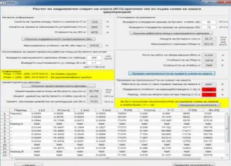
Fig. 15 Window “Calculations of the hydraulic recoil brake with control rod under the second scheme of the counter recoil (five period)
In this estimate the successive panels are:
Determination of the internal diameter of the piston stem - it is necessary to introduce the yield limit of the selected material. By clicking on the “Calculate the orientation diameter” button, the field indicating the orientation is filled in. The user-selected standard size and the adjustment ring coefficient for subsequent calculations are filled. When pressing the Calculate button the other information fields are filled in and the next panel opens directing the design engineer to the next step of the calculation algorithm.
Determining the total area of the piston’s openings and the moderator - it is again needed for the indicated fields to be filled with the indicative values below them.
Determination of the number of holes in the moderator and their diameter according to the area.
Calculating the values of Z, sqrt(z)-1, ax and Delta – this panel contains the “Enter and Calculate” button to calculate and fill the values in the table of specified values a standard control rod size is introduced into the specified field and the yield limit for the model. With the Enter and Calc buttons a follow-up "Info" panel opens.
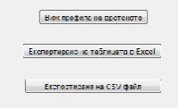
Information - this panel shows the values of the compressive stress the value of the buckling check and the reference value of the outer diameter of the cylinder according to the strength requirements. It also contains three buttons (figure 16) through which the following operations can be performed:
Fig. 16 Buttons for additional functions.
A new window opens, displaying the control rod profile through the path of the recoil (Figure 17) converted into millimeters.
Fig. 17 Control rod profile.
Export data from the estimates to an Excel spreadsheet (Figure 18).
Exporting a CSV file whit which the detail can be designed in SolidWorks.
At lowest part of the hydraulic recoil brake with a control rod reading window are the buttons:
Home - returning the program to the original screen to fill in input data and delete all data until it is clicked.
Open the value table - opening a new window with the spreadsheet (Figure 19).
Fig. 19 Calculation table. Exit - exit the program.
If one of the strength requirements is not met, the corresponding field is marked in red and a window opens with two options for adjusting the required parameters (Figure 20).
Fig. 20 Windows "Warning" and "Options".
When selecting one of the two options the window of the selected operation opens and the necessary data for the new control rod profile is entered. The user must recalculate the new parameters to meet the strength requirements.
4. Describing the design of the 3D control rod
model of the hydraulic recoil brake.
Due to the CSV file's specificity when installing the application on a new computer, it is necessary to indicate the path to the XYZ file. This is done by opening the "HSO2.m" file, finding line 1125 of the source code, and setting the exact path to the file "sw_hso.xyz" (Figure 21).
To create a SolidWorks account model, it is necessary to export the CSV file calculations from the application control rod profile and open a new project in SolidWorks.
From the Open menu, select the file "sw_hso.xyz" which contains the coordinate points for the control rod profile, open the model using the "Open" button (figure. 22).
Fig. 22 Window “Open” of SolidWorks.
Creation of a 3DSketch option is selected on the front plane (FrontPlane).
Draw a construction line along the abscissa passing through the center of the coordinate system (Figure 23).
Fig. 23 Work field in SolidWorks.
Draw a line through all the coordinate points and perpendiculars to the constructive, through the first and the last points (Figure 24).
Fig. 24 Modeling the control rod in “3DSketch”.
Exit the “3DSketch” feature and create a “2DSketch” in the front view.
From the folding menu (FutureManagerDesingTree) "3DSketch" is marked and with the function "ConvertEntities" a 2D sketch is created (Figure 25).
Fig. 25 Following steps in “2DSketch”.
Draw a line linking the two perpendiculars and proceeding from the sketch.
From the "Features" menu, select the "RevolvedBoss / Base" function by which reversed fill is performed on a selected line or point. For the axis of rotation, the last line (joining the two perpendiculars) is selected and accepted by the confirmation button (Figure 26).
Fig. 26 Software function “Revolved Boss/Base”.
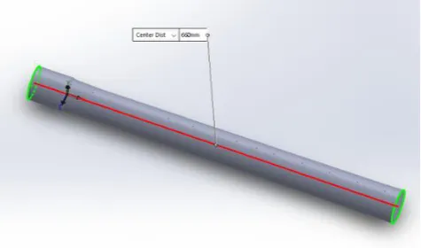
The length of the control rod is equal to that chosen by the constructor-engineer in the calculation part in millimeters (Figure 27).
Fig. 27 3D model of the control rod of the recoil brake.
5. Conclusions
The created software for calculating the recoil brake with control rod replaces the large volume of the needed calculations reduces the probability of calculation errors and enables the trainees to direct their creative thinking into a combination of different materials and / or constructive dimensions. Visualizing the final model in a 3D environment by exporting coordinate points to help draw a control rod profile.
The presented software product only provides some of the basic information needed for the creation of a recoil device in an artillery system. As further developments the creation of relations to other modeling and model calculating programs is a possibility.
REFERENCES
1. Доц. д-р. инж. Йорданов Й., MatLab 7 – Преобразувания, изчисления, визуализация, София, 2010 г.
2. Димитров Д., Проектиране на артилерийска материална част (учебник), Шумен, 1990 г.
3. Давидов Кр., Ръководство за решаване на практически задачи по проектиране на въоръжението, Шумен, 1993 г.