http://www.sciencepublishinggroup.com/j/es doi: 10.11648/j.es.20170203.12
CFD Study to Enhance the Heat Transfer in Heat Exchanger
by Change the Outer Surface of the Inner Tube and Use
Nano Fluid
Zena K. Kadhim, Safaa Abed Mohammad
Mechanical Engineering Department, Wasit University, Wasit, Iraq
Email address:
[email protected] (Z. K. Kadhim), [email protected] (S. A. Mohammad)
To cite this article:
Zena K. Kadhim, Safaa Abed Mohammad. CFD Study to Enhance the Heat Transfer in Heat Exchanger by Change the Outer Surface of the Inner Tube and Use Nano Fluid. Engineering Science. Vol. 2, No. 3, 2017, pp. 58-68. doi: 10.11648/j.es.20170203.12
Received: February 21, 2017; Accepted: March 6, 2017; Published: April 19, 2017
Abstract:
In the present work the analysis of three different copper tubes (smooth tube, two corrugated tubes withcorrugated ratio (z/d=1 and 0.5)) in a shell and tube heat exchanger done by ANSYS FLUINT14.0. This work deals with theoretical investigation was to evaluate the benefit of changing the shape of inner tube in the heat exchanger and the improving the heat transfer using water as the working fluid in the first case, then using a Nano fluids as a heat transfer working fluid. The conditions used in the simulation are in the two case the hot side flow rate range from (1 to 5 LPM) with three different temperature (40, 50 and 60°C). The cold side flow rate range (3 to 7LPM) for water and (3.2 to 7.2LPM) for nano fluid because of the change in density by added nanoparticles and at 25°C for the two cases. The simulation show results of enhancement in heat transfer rate ranging from (58.24% to 59.55%) at a temperature of 40°C, (55.62% to 58.09%) at a temperature of 50°C and (54.44% to 59.17%) at a temperature of 60°C, for both corrugated tubes with respect to smooth tube by used water as cooling fluid. By using Nano- fluid the enhancement in heat transfer are (60.14% to 61.44%) at a temperature of 40°C, (58.36% to 62.01%) at a temperature of 50°C and (56.46% to 63.15%) at a temperature of 60°C, for both corrugated tubes with respect to smooth tube.
Keywords:
Heat Exchanger, Corrugated Tube, Nano-Fluid1. Introduction
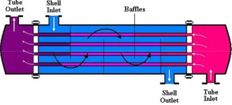
A heat exchanger is a device that is used to transfer heat between two or more fluids that are at different temperatures. Heat exchangers are essential elements in a wide range of systems, including the human body, automobiles, computers, power plants, and comfort heating/cooling equipment [1]. The most commonly used type of heat exchanger is the shell-and-tube heat exchanger show in figure (1), the enhancement of heat transfer rate which is the main objective of this study [2].
The fundamental basis for this statistic is shell and tube technology is a cost effective, proven solution for a wide variety of heat transfer requirements. There are limitations associated with the technology which include inefficient usage of shell side pressure drop, dead or low flow zones around the baffles where fouling and corrosion can occur, and flow induced tube vibration, which can ultimately result in equipment failure. A heat exchanger is a component that
allows the transfer of heat from one fluid (liquid or gas) to another fluid [3].
Increasing heat exchanger performance usually means transferring more duty or operating the exchanger at a closer temperature approach. This can be accomplished without a dramatic increase in surface area [2].
Figure 1. Structure of shell and tube type heat exchanger.
effect of using it with different particle volume concentrations (0.5-3%). It was found that the effectiveness of shell and tube heat exchanger increments by 6.2% because of increment in volume focus from (0.5% to 3%). Less coolant pumping force is required for exchanger worked with Al2O3/water Nano liquid contrasted with base liquid.
Subsequently, there is a general change in execution of shell and tube heat exchanger because of the utilization Nano fluid.
Aphichat Danwittayakul et al., 2015, [5] study to find the heat transfer efficiency by using several percentage weight of alumina Nano-particles. Alumina Nano-particles (less than<50 nm) in size was used. Used five concentrations of Nano fluid were applied in the hot line. Flow rate of Nano fluid was set as 30 cm3/s and ṁ cold were change from (10 to 50) cm3/s. The result is show that the highest Heat
Sekhar et al., 2014, [3] presented numerical investigation for pressure drop (∆P) variations in multi tube pass STHE as well as the (h) was obtained. ∆P for 1,2,4,6 tube pass STHE were find by using “C PROGRAMING” and compared with “Bell Manual Method” values. It was concluded that 4 tube pass is to be better than 6 tubes pass since 4 tubes pass and ∆P is less than its allowable.
Saqheeb Ali et al., 2015, [6] Study The effect of thickness of fin tube in temperature and the mass flow rat study theoretically. The CFD examination is finished by utilizing the ANSYS. The outcomes which acquired with three diverse sorts of material's steel, aluminum and copper, finding to exceptionally minor changes happen in the weight and speed with increment of blade thickness and get high temperature at outlet in the event of Aluminum and copper contrasted with steel material. At the point when increment the balance thickness the temperature of the chilly liquid at the outlet of the warmth exchanger increments. By diminishing the mass stream rate for there is expanding the estimation of temperature.
2. Numerical Models
Numerical analysis is use to simulate the heat exchange in countercurrent flow heat exchanger between water/water and water/Nano fluid [hot water flow in tubes and cold water or Nano fluid flow in shell] through the tubes wall. The simulation is done by ANSYS-Fluent 14.0 with different conditions.
This study included different parameters such as tube types are smooth tube and corrugated tubes with corrugate ratio z/d= 1 and 0.5, hot mass flow rate change from (1 to 5) LPM, its temperature ranging from (40 to 60°C) and cold water mass flow rate are change for the change the hot water mass flow rate from (3 to 7) LPM for water without Nano and from (3.1 to 7.1) LPM for Nano fluid at temperature 25°C, This is doing for all tube.
3. Design of Geometry
The test sections for smooth copper tube have (17.05,
19.05 mm) as inner and outer diameter and corrugated tube (42.6, 50 mm) inner and outer diameter for P. V. C outer tube. With the length is (1m). Sketch by used a SOLI D WORK PREMIUM 2015 program, as shown in figure (2) and table (1). After the geometry is drawn and saving, it is exported to GAMBIT 2.3.6 to made meshing and other activities for all volumes and saved. Then exported to ANSYS 14.0 to read it and be ready for boundary condition shown in table (2) and start simulation in FLUINT.
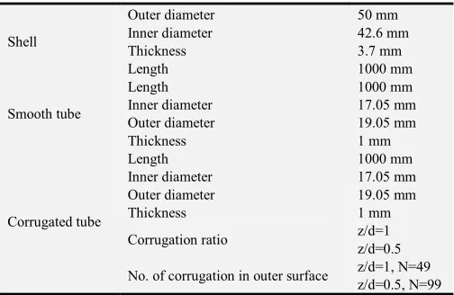
Table 1. Geometric Parameters of Shell and Tube Heat Exchanger.
Shell
Outer diameter 50 mm Inner diameter 42.6 mm Thickness 3.7 mm Length 1000 mm
Smooth tube
Length 1000 mm
Inner diameter 17.05 mm Outer diameter 19.05 mm Thickness 1 mm
Corrugated tube
Length 1000 mm
Inner diameter 17.05 mm Outer diameter 19.05 mm Thickness 1 mm
Corrugation ratio z/d=1 z/d=0.5
No. of corrugation in outer surface z/d=1, N=49 z/d=0.5, N=99
Where:
z: longitudinal distance (mm), d: tube diameter (mm), N: number of grooves in outer tube surface.
Table 2. Boundary condition.
Case 1 Water/water
Tube side (hot side)
Inner mass flow rate 1 to 5 LPM Inner temperature 40 to 60°C Shell side
(cold side)
Inner mass flow rate 3 to 7 LPM Inner temperature 25°C
Case 2 Water/Nano fluid
Tube side (hot side)
Inner mass flow rate 1 to 5 LPM Inner temperature 40 to 60°C Shell side
(cold side)
Inner mass flow rate 3.1 to 7.1 LPM Inner temperature 25°C
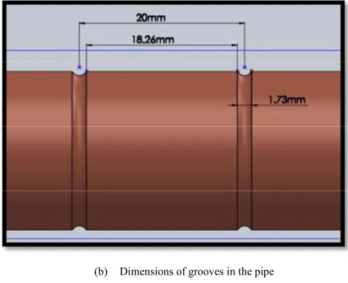
(b) Dimensions of grooves in the pipe
Figure 2. Test section geometry.
4. Numerical Simulation
Numerical simulation doing analysis of advanced phenomena in engineering implementation. It is the analysis of a system including fluid flow, heat transfer and other parameters on various departments of science. The numerical simulation across three-dimensional model for the heat exchanger adopting by using ANSYS FLUENT 14, in order to analyze the flow field in the heat exchanger using the solution of energy equation, momentum equation and conservation continuity. Comparison results for smooth and corrugated tubes is carried out.
5. Assumptions
The following assumptions are used during the present study for hot and cold water:
Steady state. Newtonian fluid. Incompressible. Three dimensional.
Turbulent flow in the inner side (hot water), in Re range from 1800 to 13000.
Laminar flow in the outer side (cold water), in Re range from 1650 to 1900.
Negligible buoyancy.
Radiation heat transfer is not considered.
6. Boundary Conditions
The performance rating of the heat exchanger in this work, some requirements of the physical sample are defined adequately as follows:
Inlet Boundary Conditions
Inlet velocity was fixed for inner (hot section) and outer (cold section) sides during this study. The temperature inlet of the hot section are (40, 50, 60°C) and in the cold section is (25°C).
Pressure Outlet Boundary Conditions
The outlet domain is set as pressure outlet for the hot and cold section.
Wall Boundary Condition
No slip boundary condition is set in the wall of the inner tube. Use this condition for both fluid and solid region.
7. Governing Equations for Laminar and
Turbulent Flow
7.1. Laminar Flow
The governing equations for energy, momentum and continuity are described in the following sections [7]:
7.1.1. Continuity Equation
0 (1)
7.1.2. Momentum Equation
(2)
(3)
(4)
7.1.3. Energy Equation
! " " # " $ " " " (5)
7.2. Turbulent Flow
The governing equations for energy, momentum and continuity are described in the following sections [8]:
7.2.1. Continuity Equation
% % %
0 (6)
7.2.2. Momentum Equation
& % ̅ % #% % &&&&&&&() &&&&&&&&( ( &&&&&&&&&(#( *
+ ,-)& (7)
& % ̅ % #% % &&&&&&&() &&&&&&&&( ( &&&&&&&&&(#( *
+ ,-)& (8)
& % ̅ % #% % &&&&&&&() &&&&&&&&( ( &&&&&&&&&(#( *
7.2.3. Energy Equation
& "& ̅ "& #% "& .-)/& &&&&&&&&(/( &&&&&&&&(/( &&&&&&&&&#(/( (10)
7.2.4. Transport Equations
I. K Equation
& 0 ̅ 0 #% 0 1 23
45
0 0 0 6 7
0 ∈ (11)
II. ϵ Equation
& ∈ ̅ ∈ #% ∈ 1 23
4∈
∈ ∈ ∈ 6
*∈∈070 )∈ ∈0 (12)
Where:
70 9:) (13) S = the modulus of the main rate-of-strain tensor.
GK = generation of turbulent kinetic energy due to mean
velocity gradients.
*∈ 1.42 (14) )∈ 1.68 (15)
8. Mesh Generation
Unstructured mesh is applied in the present study to discretize the computational field into a finite number of control volumes by using the finite–volume scheme. Structured mesh is ruled out because it is favorable for easy cases and it becomes insufficient and time consumed for complicated geometries. By used GAMBIT software, the model was meshed. It is worth mentioning that convenient numerical control and modeling techniques are very
important to step up convergence and stability during the calculation. By adopting control–volume technique, FLUENT shifts the governing equations to algebraic equations that can be solved numerically. The control volume is technique involves of integrating the governing equations inside each control volume, yielding discrete equations [9].
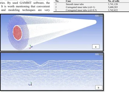
Triangular element type is used for meshing the surface. Tetrahedron element type is employed for 3D geometry; this is because it has favor in the advanced geometries. Mesh of present model show in figure (3a) and figure (3b) show mesh in corrugated area of tube. Table (3) show number of cells in mesh for all cases.
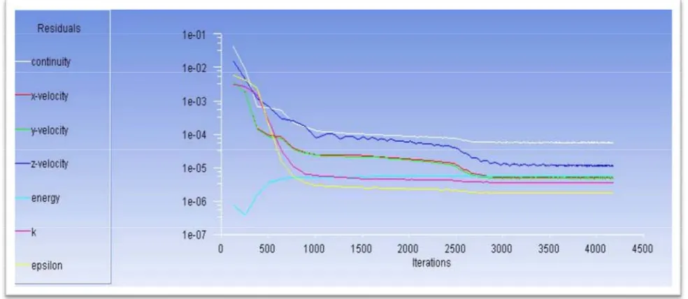
The iterations are needed in this study (4200) as shown in figure (4). It is the maximum number of iterations needed to get the solver terminates and by converge.
Table 3. Number of cells in mesh.
No. Case No. of cells
1 Smooth inner tube 3,741,120 2 Corrugated inner tube (z/d=1) 3,680,203 3 Corrugated inner tube (z/d=0.5) 3,742,822
Figure 4. Residual for numerical simulation of present study.
9. Numerical Results Analysis
In order to validate numerical simulation, a comparison has done with past numerical results completed by Özden Ağra et.al [10] which presented the numerical studies for different tubes and covering a vast range of Reynolds from (12000 to 57000), and study the effect of the shape geometry and change its parameter as helix angle and effect of corrugated in inner and outer tube surface. They have performed a numerical study for predicting temperature different, heat dissipation and fraction factor. In general, the good convention of behavior between these results has been found which denote the accepted validation of present simulation, in figure (5) see the convergence in result.
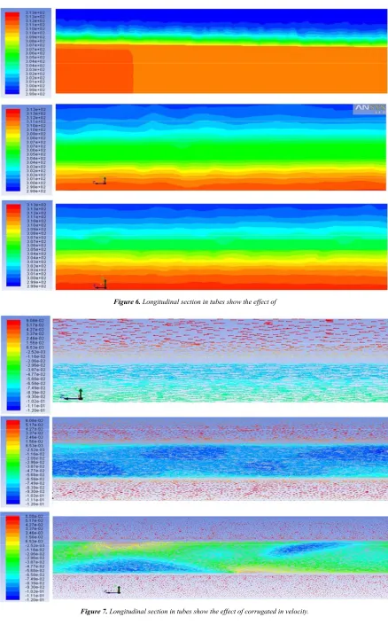
The longitudinal section in tubes show in figure (6a, b and c) illustrated the turbulence flow that occurs in the boundary layer which create from corrugated in outer surface, as well as from figure (7a, b and c) can see the change in velocity flow behavior due to the change in the (z/d) and the surface area due to corrugated surface tube. The turbulence in this case assists to increase the heat transfer at mass flow rate 3 LPM.
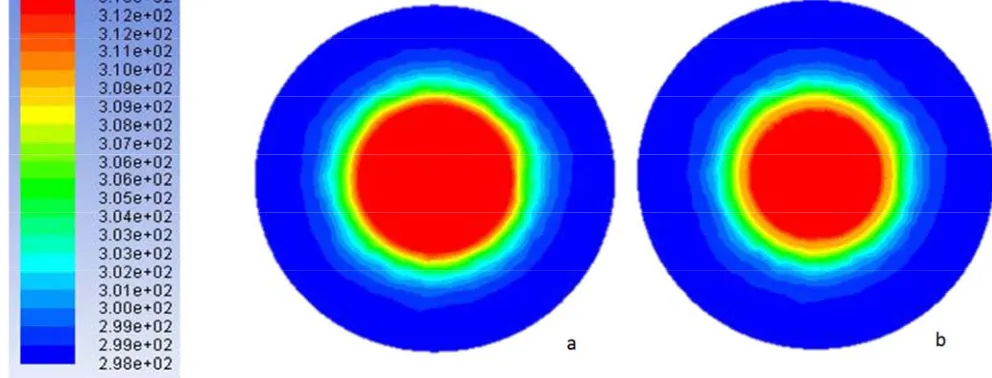
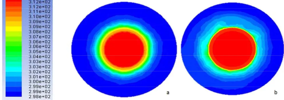
Figures (8a and b) to (10a and b) cross section at 50cm for test section, can see the conduct of fluid in tube and shell side and the change that occurs by change the cold water flow rate from 3LPM to 7LPM and tube geometry from smooth to corrugated. We can see the change in hot water behavior clearly into the center of the hot water. This be more when we used nano fluid as shown in Figures (11a and b) to (13a and b) cross section at 50cm for test section, show the dual effect of used Nano fluid instead of water in shell side and use of different ratio of corrugated tube, as well as the potential advantages due to include higher thermal conductivity than the pure fluid. In figures from (8a and b) to (13a and b) we selected at 50 cm to see the effect that
happened at the middle of the tube length.
Figures (14a and b) to (16a and b) cross section at 100cm for test section from hot water in, can see the behavior of fluid in tube and shell side and the change that occurs by change the cold water flow rate from 3LPM to 7LPM and tube geometry from smooth to corrugated. can see the great pervasion of heat in cold water because in this point the different in temperature between cold and hot water is high, this made high transfer of heat. This be more when we used nano fluid as shown in Figures (17a and b) to (19a and b) cross section at 100cm for test section from hot water in, show the dual effect of used Nano fluid instead of water in shell side and use of different ratio of corrugated tube, as well as the potential advantages due to include higher thermal conductivity than the pure fluid.
In figures can see the pervasion of heat in nano fluid (cold side) because in this point the different in temperature between cold and hot side is high, and nano fluid has a high affinity to pull heat this made high transfer of heat.
Figure 6. Longitudinal section in tubes show the effect of
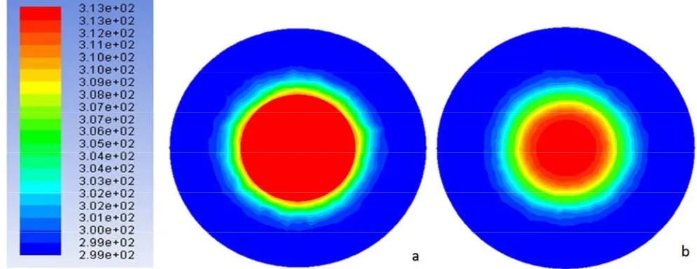
Figure 8. Section in z=50cm in test section smooth tube at Th=40 °C, (a) at ṁc=3LPM (b) at ṁc=7LPM.
Figure 9. Section in z=50cm in test section corrugated tube (z/d=1) at Th=40 °C, (a) at ṁc=3LPM (b) at ṁc=7LPM.
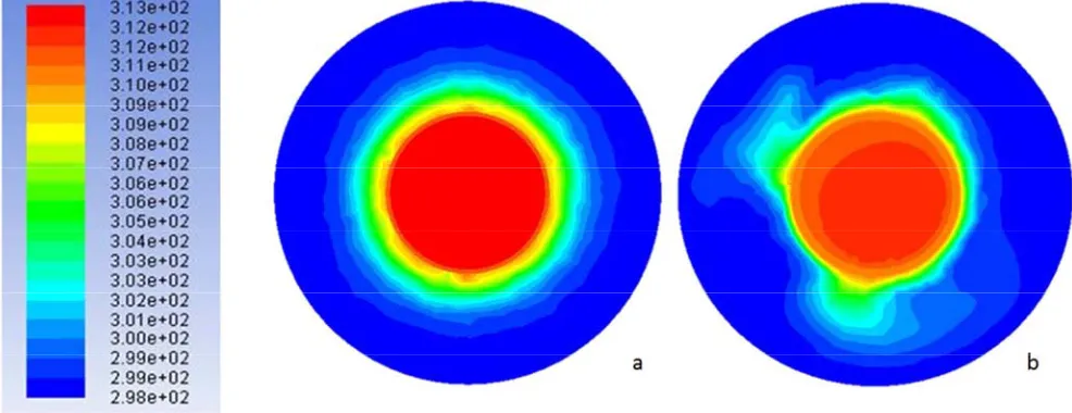
Figure 11. Section in z=50cm in test section smooth tube at Th=40 °C, (a) at ṁc=3LPM (b) at ṁnano=3.1LPM
Figure 12. Section in z=50cm in test section corrugated tube (z/d=1) at Th=40 °C, (a) at ṁc=3LPM (b) at ṁnano=3.1LPM.
Figure 14. Section in z=100cm in test section smooth tube at Th=40 °C,(a) at ṁc=3LPM (b) at ṁc=7LPM.
Figure 15. Section in z=100cm in test section corrugated tube (z/d=1) at Th=40 °C,(a) at ṁc=3LPM (b) at ṁc=7 LPM.
Figure 17. Section in z=100cm in test section smooth tube at Th=40 °C,(a) at ṁc=3LPM (b) at ṁnano=3.1LPM.
Figure 18. Section in z=100cm in test section corrugated tube (z/d=1) at Th=40 °C, (a) at ṁc=3LPM (b) at ṁnano=3.1LPM.
Figure 19. Section in z=100cm in test section corrugated tube (z/d=0.5) at Th=40 °C, (a) at ṁc=3LPM (b) at ṁnano=3.1LPM.
10. Conclusions
In this work the important enhancement in heat transfer in
prominent augmentation in heat transfer for heat exchanger. The behavior of the hot temperature difference inversely with increase hot water mass flow rates, but the heat dissipation directly proportionally and the behavior of cold temperature difference is increase directly proportional with hot mass flow rate and inversely with cold mass flow rate.
The maximum enhancement in heat transfer rate ranging from (58.24% to 59.55%) at 40°C, (55.62% to 58.09%) at 50°C and (54.44% to 59.17%) at 60°C for both corrugated tubes with respect to smooth tube by used water as cooling fluid. The enhancement in heat transfer are (60.14% to 61.44%) at 40°C, (58.36% to 62.01%) at 50°C and (56.46% to 63.15%) at 60°C for both corrugated tubes with respect to smooth tube by used Nano fluid as cooling fluid.
References
[1] Resat Selbaşa, Önder Kızılkana, Marcus Reppichb, “A new design approach for shell-and-tube heat exchangers using genetic algorithms from economic point of view”, Chemical Engineering and Processing: Process Intensification, Volume 45, Issue 4, April 2006, Pages 268–275.
[2] Kevin M. Lunsford, “Increasing Heat Exchanger Performance”, Bryan Research and Engineering, Inc. – Technical Papers, Bryan, Texas, 1998.
[3] B. Chandra Sekhar, D. Krishnaiah, F. Anand Raju, “Thermal Analysis of Multi Tube Pass Shell and Tube Heat Exchanger”, International Journal of Innovative Research in Science,
Engineering and Technology, vol. 3, Issue 11, November 2014, Pages 17605-17612.
[4] Arun Kumar Tiwari, “Thermal Performance of Shell and Tube Heat Exchanger Using Nano fluids”, IJAPME, Vol. 1, Issue -1, 2015, 27-31.
[5] Aphichat Danwittayakul, Cattaleeya Pattamaprom, “Investigation of Heat Transfer Efficiency of Alumina Nano fluids in Shell and Tube Heat Exchanger”, IPCBEE, Vol.82, 2015, pp. 68-72.
[6] Sk. M. Z. M. Saqheeb Ali, k. Mohan Krishna, S. D. V. V. S. Bhimesh Reddy, sk. R. S. M. Ali, “Thermal Analysis of Double Pipe Heat Exchanger by Changing the Materials Using CFD”, IJETT, Vol. 26 Number 2, August 2015, pp. 95-102.
[7] Mon M. S. and Gross U., “Numerical study of Fin-Spacing Effects in Annular-Finned Tube Heat Exchangers”, International Journal of heat and Mass Transfer, Vol. 47, pp. 1953-1964, 2004. 39.
[8] Lars Davidson, “An Introduction to Turbulence Models”, department of thermos and fluid dynamics, Chalmers University of Technology, Sweden, 2009.
[9] N. Sahiti, F. Durst, A. Dewan, “Heat transfer enhancement by pin elements”, IJHMT, vol. 48, Issues 23–24, November 2005, Pages 4738–4747.