© 2017 IJSRSET | Volume 3 | Issue 8 | Print ISSN: 2395-1990 | Online ISSN : 2394-4099 Themed Section : Engineering and Technology
Numerical Analysis and Optimization Method to Enhance the
Performance of Heat Exchanger used in Rankine Cycle
Rajni Kant Kumar
1,
Dr. Ajay Singh
2, Prof. Ashish Verma
3 1M.E. Scholar, Radharaman Institute of Technology and Science, Bhopal, Madhya Pradesh, India
2Head and Professor, Radharaman Institute of Technology and Science, Bhopal, Madhya Pradesh, India 3 Professor, Radharaman Institute of Technology and Science, Bhopal, Madhya Pradesh, India
ABSTRACT
In order to reduce the emission of carbon mono oxide some of the researchers have inserted the pure water inside the combustion chamber at the start of the expansion stroke. Water inserted inside the chamber get instantly vaporize, due to this the pressure during the expansion stroke get increased. With the help of this increased pressure, work done during cycle gets increased. Also with the insertion of water inside the combustion chamber reduces the value of carbon mono oxide content in the exhaust gas. Here carbon reacts with oxygen and produce CO2. During
vaporization of water both sensible as well as latent heat are required, which is extract from the combustion chamber to reduce the thermal efficiency of engine. So in order to reduce the amount of heat requirement and to increase the overall efficiency of the engine, heat exchanger is used in internal combustion Rankine cycle. Here heat exchangers extract heat from the exhaust gases and transfer to pure water used inside the combustion chamber. Here in this work the effect of different flow patterns on heat exchanger has been analyzed. Also, investigated the effect of mass flow rate of water inside the tube. Furthermore, the effectiveness and overall heat transfer coefficient of heat exchanger.
Keywords: CFD analysis, Heat exchanger, flow pattern, Oxy-fuel combustion, water injection, waste heat recovery.
I.
INTRODUCTION
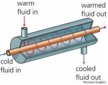
Heat exchanger is a device which is mostly used in equipment to transfer heat between two process streams which may be in direct contact or may flow separately in channels or tubes [1]. We find numerous applications and one can realize their usage that any process which involves cooling, heating, condensation, boiling or evaporation will require a heat exchanger for these purposes [4]. Similarly the heat exchangers used in automobile industries are in the form of radiators and oil coolers in engines [3]. Heat exchangers are also used in large scale in chemical and process industries for transferring the heat between two fluids which are at a single or two states [2].
1.1 Type of Heat Exchanger
1.1.1 Direct contact type-
Direct contact type heat exchangers are the heat exchanger in which two immiscible fluids are directly mixed with each other to transfer heat between two fluids [7]. The efficiency of this type Heat exchanger is
more compared to other type heat exchangers. Cooling tower, jet condenser, de-super heaters, open feed water heater are the example of this type of heat exchanger [7].
1.1.2 Transfer type-
Transfer type or Recuperate type heat exchanger two fluid flows simultaneously through two tubes separated by walls [7].
1.1.3 Regenerator type-
Regenerator type heat exchanger the hot and cold fluid flow alternatively on same surface. During the hot fluid transfer the wall of exchanger get heated and when the cold fluid flows through it, this heat get transferred from the wall of the heat exchanger to the cold fluid so that the temperature of cold fluid increases [7]. The common examples of these type heat exchangers are pre-heaters for steam power plant, blast furnace etc [7].
heat exchanger used in the experimental analysis performed by zhijun et.al [8].
Figure 1. Showing the Heat Exchanger [6]
Here the solid model of heat exchanger is drawn on ANSYS and then it is analyzed in the fluent module. The workbench of the ANSYS is shown in the fig. 2
Figure 1. Showing the Development of the Solid Model of Heat Exchanger
The solid model of the heat exchanger, which is used for the numerical analysis in the work, is shown in the fig. 3
Figure 3. Showing the Solid Model of the Heat Exchanger
Here in this analysis the geometrical dimension of the heat exchanger is based on the experimental heat exchanger used by the author in the base paper [8]. The geometric dimension of the heat exchanger is shown in the table 1.
Table 1. Showing the Geometric Dimension of the Heat Exchanger
Parameter Values
Heat Transfer Area 0.848 m2
Tube Numbers 9
Tube Length 1m
Tubes Center 0.02 m
Tube Diameter 0.03 m
Tube Thickness 0.0005 m
Shell Diameter 0.3 m
Shell Thickness 0.003 m
II.
MESHING
In order to perform the numerical analysis first it distributes the complete body into the small size of the element [5]. Here during the meshing inflation command is used in order to deal with the critical zone in highly complicated geometry. The meshing of the given solid model of the heat exchanger is show in the fig. 4 and fig. 5.
Figure 4. Showing the Mesh of the Heat Exchanger
Figure 5. Showing the Mesh of the Heat Exchanger
analysis the outer shell tube is made of the aluminum. The material properties of the aluminum are shown in the given table 2.
Table 2. Showing the Material Properties of Aluminum
Parameter Values
Density (kg/ 2719
Specific Heat (J/kg-K) 871 Thermal Conductivity (w/m-K) 202.4
Whereas the inner tube through which the cold water at very high pressure is flowing is made from copper [9]. Here in this analysis the hot exhaust gas is flowing inside the shell tube whereas the cold water is flowing inside the inner tube of the heat exchanger. So the material properties of the copper is shown in the below table 3.
Table 3. Showing the Material Properties of Copper
Parameter Values
Density (kg/ 8978
Specific Heat (J/kg-K) 381 Thermal Conductivity (w/m-K) 387.6
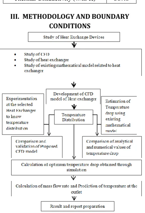
III.
METHODOLOGY AND BOUNDARY
CONDITIONS
In this analysis exhaust gases coming from the engine are used as a heating agent inside the heat exchanger. The heating gases is at near about [8], with the help of heat exchanger heat is transfer from the exhaust gas to the water which is used to feed inside the combustion chamber. Here in this analysis heat first transfer from exhaust gas to the inner tube outer surface through convection, inside the tube through conduction and then from tube inner surface to water through again convection [10]. The water is inserted into the heat exchanger at 299.85 K temperature and at 20 MPa pressure [8].
Different conditions applied at the heat exchanger are shown in the table 4.
Table 4. Showing the Boundary Condition
Parameters Value
Inlet Water Temperature
299.85 K
Inlet Water Pressure 20 Mpa Inlet Exhaust Gas
Temperature
1673 K
Inlet Mass Flow Rate of Exhaust Gas
0.04 kg/s
IV.
RESULTS AND DISCISSION
Here in this analysis, in order to increase the performance of the heat exchanger used inside the Rankine cycle different flow pattern of heat exchanger with different mass flow rate of fluid were analyzed. In this research three different types of flow pattern that is parallel flow, counter flow and cross flow are used. The effect of different mass flow rate that is 0.02, 0.03 0.04, 0.05, 0.06 and 0.07 kg/s of fluid on all the three types flow pattern of heat exchanger has been observed. Furthermore, the effect of different mass flow rate on different flow pattern has been analyzed to obtain the best result.
4.1 Parallel Flow
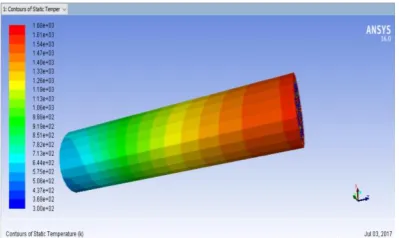
Figure 6. Showing the Contour of the Temperature for the Parallel Flow
The temperature distribution throughout the heat exchanger the maximum temperature at the exit of the water is near about 330 K for the case having the parallel flow during the operation [10]. From the above analysis it is conclude that the temperature at the exit of the water is less, so in this case the transfer of heat from the exhaust gas to the water is less. For this case it has also analyzed the temperature distribution inside the water tube. The temperature distribution inside the water is shown in the fig. 7.
Likewise the above case of parallel flow for mass flow rate 0.02 kg/s, it also analyzed the parallel flow analysis for two other mass flow rate that is 0.03, 0.04, 0.05 and 0.06 kg/s. the temperature obtained during the analysis at different mass flow rate is shown in the table 5.
Figure 7. Showing the Temperature Distribution inside the Water for Parallel Flow
4.2 Counter Flow
Here in this case Cross flow type of heat exchange is consider, here in this type of flow pattern the exhaust gas and the water fluid are flowing in the opposite direction to each other [12]. During the analysis the mass flow rate of the water is 0.04 kg/s the temperature distribution of the water inside the inner tube is shown in the fig. 8.
Figure 7. Showing the Temperature Distribution Inside the Heat Exchanger
From the above result is analyzed that the temperature of water at the exit of the heat exchanger is near about 522 K, during this case the mass flow rate of the water is 0.04 kg/s. The temperature distribution inside the heat exchanger for this case is shown in the fig. 9.
Figure 8. Showing the Temperature Distribution at the Inlet and Exit of the Heat Exchanger
From the above analysis it is found that the value of water temperature at the exit of the heat exchanger is near about 522 K. Heat transfer analysis having different mass flow rate is also analyzed in the counter flow case in Table 5.
4.3 Cross Flow
as the mass flow rate increases the value of the temperature at the exit of the heat exchanger is also increasing. The comparison Table 5 in between the all pattern of flow is.
Table 5. Showing the Comparison of Temperature at Different Mass Flow Rate at Different Pattern
Flow Pattern
Mass Flow Rate (kg/s)
Temperature of Water at the Exit
of Heat Exchanger (k)
Parallel Flow
0.02 330
0.03 368
0.04 417
0.05 469
0.06 494
0.07 501
Counter Flow
0.02 403
0.03 458
0.04 522
0.05 589
0.06 624
0.07 634
Cross Flow
0.02 457
0.03 527
0.04 629
0.05 733
0.06 781
0.07 789
Graph 1 Showing the Comparison of Water at Exit Temperature in Respect to Mass Flow Rate
From the Graph 1, it is analyzed that the as the mass flow rate increases in any of the flow pattern inside the heat exchanger, the value of the water temperature at the exit of the heat exchanger also goes on increasing. And out of the three different pattern of flow it is clear that the cross flow is more efficient other than the parallel and counter flow [13].
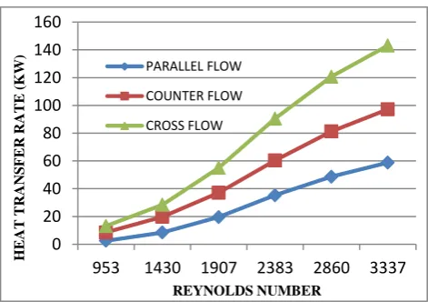
Based on the analysis it is found that the value of heat transfer get increase as the Reynolds number increases [15]. From the graph 2 it is shows that the heat transfer is higher in case of cross flow as compared to the parallel and counter flow at same Reynolds number.
Graph 2. Showing the change in Heat Transfer for Different Flow Pattern at Different Reynolds Number
It is found that as the Reynolds number increases the value of heat transfer get increases. It shows that as the Reynolds Number increases above 2000 the liquid flow behavior changes from lamina to turbulent flow and from graph it shows that, as the turbulence increases the rate of heat transfer from the exhaust gas to water get increases. Through graph, it also found that at the same Reynolds Number the value of heat transfer rate for cross flow is more as compared to the parallel and counter flow type heat exchanger.
4.4 Effectiveness
Here in this work we have also calculate the value of effectiveness of heat exchanger for different flow pattern of heat exchanger [15]. The effectiveness of different flow pattern is shown in the Graph 3.
0 100 200 300 400 500 600 700 800 900
0.02 0.03 0.04 0.05 0.06 0.07
W A T E R T E M PE R A T U R E ( K)
MASS FLOW RATE (kg/s) WATER TEMPERATURE AT EXIT FOR DIFFERENT MASS FLOW RATE IN DIFFERENT
PATTERN PARALLEL FLOW COUNTER FLOW CROSS FLOW 0 20 40 60 80 100 120 140 160
953 1430 1907 2383 2860 3337
Graph 3. Showing the Comparison of Effectiveness for Different Mass Flow Rate
V.
CONCLUSIONS
As the heat exchanger is used in the Rankine cycle, its work is to extract heat from the exhaust gas coming from the combustion chamber of the engine and give it to the water which is used as to feed inside the combustion chamber in order to increase the pressure inside the combustion chamber. After analysis the different case following conclusion obtained
i. It is found that the value of water temperature at the exit of the heat exchanger can be increase by approaching with the different flow pattern and different mass flow rate of fluid.
ii. Here it has analyzed the three different pattern of flow that is parallel flow, counter flow, cross flow with varying mass flow rate.
iii. It is found that as the mass flow rate increases the heat transfer from the exhaust gas to water is also increase, due to this the temperature of water get increased
iv. As the direction of the flow of both fluid changes the heat transfer in between exhaust gas and water also changes.
v. From the above the analysis it is clear that the value of the water temperature at the exit of the heat exchanger during the cross flow is maximum at 0.06 kg/s mass flow rate.
During the section of cross flow analysis it is find that as the mass flow rate increases the value of the temperature at the exit of the heat exchanger is also increasing.
VI.
REFERENCES
[1]. Aly Wael I.A., Numerical study on turbulent heat transfer and pressure drop of nano fluid in coiled
tube-in-tube heat exchangers, Energy Conversion and Management, vol.-79 (2014), pp.304-316.
[2]. Carlos G Aguilar-Madera, Francisco J Valdés-Parada, Benoit Goyeau & Alberto Ochoa-Tapia J 2011, 'Convective heat transfer in a channel partially filled with a porous medium', International Journal of Thermal Sciences, vol.50, pp.1355-1368.
[3]. Li, HY, Leong, KC, Jin, LW & Chai JC, 2010, 'Analysis of fluid flow and heat transfer in a channel with staggered porous blocks', International Journal of Thermal Sciences vol. 49, pp. 950-962.
[4]. Dae Hee Lee, Jun Sik Lee & Jae Suk Park (2010) Effects of secondary combustion on efficiencies and emission reduction in the diesel engine exhaust heat recovery system Applied Energy 87, pp.1716-1721. [5]. Dexin Wang, Ainan Bao, Walter Kunc & William Liss
(2012) Coal power plant flue gas waste heat and water recovery Applied Energy vol. 91, pp.341-348.
[6]. Eiamsa-ard Smith, Promvonge Pongjet, Enhancement of heat transfer in a tube with regularly-spaced helical tape swirl generators, Solar Energy, vol.-78 (2005), pp. 483-494.
[7]. Rajput R K, Heat and ass Transfer, Edition - 5th (2012), pp. 574-577.
[8]. Zhijun Wu, Lezhong Fu, Yang Gao, Xiao Yu, Jun Deng, Liguang Li, Thermal efficiency boundary analysis of an internal combustion Rankine cycle engine, Energy, vol.-94(2016), pp. 38-49.
[9]. Eiamsa-ard Smith, Promvonge Pongjet, Heat transfer characteristics in a tube fitted with helical screw-tape with / without core-rod inserts, International Communications in Heat and Mass Transfer, vol.-34 (2007), pp. 176-185.
[10]. Emanuel Feru, Bram de Jager, Frank Willems & Maarten Steinbuch (2014) Two-phase plate-fin heat exchanger modeling for waste heat recovery systems in diesel engines' Applied Energy, vol.133, pp. 183- 196. [11]. Ferng Y. M., Lin W. C., Chieng C. C., Numerically
investigated effects of different Dean number and pitch size on flow and heat transfer characteristics in a helically coil-tube heat exchanger, Applied Thermal Engineering, vol.-36 (2012), pp. 378-385.
[12]. Ghorbani Nasser, Taherian Hessam, Gorji Mofid, Mirgolbabaei Hessam, An experimental study of thermal performance of shell-and-coil heat exchangers, International Communications in Heat and Mass Transfer, vol.-37 (2010), pp. 775-781.
[13]. Gianfranco Caruso, Fabio Giannetti & Antonio Naviglio (2015) An Experimental Study on the Air-Side Heat Transfer Coefficient and the Thermal Contact Conductance in Finned Tubes, Heat Transfer Engineering, vol.36, pp. 212-221.
[14]. Horng-Wen Wu & Ren-Hung Wang 2010, 'Convective heat transfer over a heated square porous cylinder in a channel', International Journal of Heat and Mass Transfer, vol.53, pp.1927-1937.
[15]. Huminic Gabriela, Huminic Angel, Heat transfer characteristics in double tube helical heat exchangers using nano fluids, International Journal of Heat and Mass Transfer, vol.-54 (2011), pp. 4280-4287.
0 0.1 0.2 0.3 0.4 0.5 0.6
0.02 0.03 0.04 0.05 0.06 0.07
EF
FE
C
TIV
ENES
S
MASS FLOW RATE (kg/s)