A NON-ELITIST MULTI OBJECTIVE
GENETIC ALGORITHM FOR AXIAL
COMPRESSOR STAGE OPTIMIZATION
G.CHAITANYA
*Department of Mechanical Engineering
R.V.R &J.C college of Engineering, Guntur-522007, AP, India
DR.J.SURESH KUMAR2
Department of Mechanical Engineering JNTU Hyderabad-85, Andhra Pradesh, India
DR.K.SRINIVAS3
Department of Mechanical Engineering
R.V.R &J.C college of Engineering Guntur-522007, AP, India
Abstract:
A non-dominated sorted Genetic Algorithm approach proposed by Goldberg and later refined by Srinivas & Deb has been implemented with appropriate sharing function value for stage optimization of axial compressor. The objectives for the multi objective problem are Stage Efficiency, Inlet stage specific Area & Stall margin Coefficient. Jin Shik Lim and Myung kyoon Chung performed the optimization axial compressor stage taking two objective functions, stage efficiency and stage weight into consideration and by taking eight design variables. In the present approach the problem is modeled as a three objective function problem with five design variables. NSGA technique is implemented and Results were analyzed for non dominated solution fronts among the three objective functions and sensitivity of design variables
on objective functions has been studied.
Keywords: Sharing function, Efficiency, Stall-Margin, NSGA, Specific Area Nomenclature:
D: Mean diameter of Stage (mts) Ø: Flow Coefficient α1: Air angle at inlet to rotor (Radians) N: Shaft speed in (rps)
σsh : Sharing function K: Blade hub-tip radius ratio
h : Blade mean height (m) α : Sharing function index (1,2..) p : Pressure ratio U : Mean peripheral Velocity (m/s) m: Mass flow rate (kg/s) , ((γ -1)/ γ) g: Gravitational Acceleration (m/s2) T: Temperature (k) γ: Process index (1.4 for air) J: Mechanical equivalent of heat (kj/kj) (t/c) : Blade thickness / Chord ratio ρ : Air density (kg/m3) ρb : Blade density (kg/m3)
(c/D) : Chord / Diameter ratio Cp : Specific heat (kj/kgk)
Ca : Axial velocity component (m/s) ρb : Blade density (kg/m 3
)
λ: Work done factor dij : Distance between solution i & j
n : Number of blades v11 : Velocity in relative frame of reference
cw : Whirl component of velocity f1 , f2 , f3 : Objective functions
Suffixes: Abbreviation:
1, 01: Rotor Inlet NSGA: Non dominated Sorted Genetic Algorithm 2, 02: Stator Inlet
Introduction:
In the design of axial flow compressors for both aero space and industrial applications, stage efficiency and stall margin forms important design criteria which demand specific attention. Stage weight also forms an important criterion especially in case of aero space compressors. [ Sehra, Bettner & Cohn (1992) ] implemented design techniques used in air craft compressors to compressors used for industrial engines. [ Koch (1981) ] presented an engineering approach of predicting stalling pressure rise in case of axial compressors. Stall margin semi-empirical model developed by [ Koch (1981)] was based on General Electric low speed multi stage compressor test configurations. [Liebliein (1959)] has provided a quantitative measure for determining loading at stall condition. [Smith (1970) ] presented the effect of end wall losses and blade aspect ratios on efficiencies and stall of axial compressors. [Massardo & Satta (1990)] have provided optimum design relations for axial compressors used for industrial applications. [Rao & Guptha (1980)] formulated a non linear mathematical model for minimization of mass and aerodynamic losses in the stage of axial compressor.[Roger & Sarvanamatoo (1989)] Provided the basic thermodynamic relations and stage design relations for axial compressors. In this paper the compressor is assumed to be a fifty percent reaction stage compressor with symmetrical blade angles and air inlet flow angle equal to blade exit angle and vice versa. The primary advantage with fifty percent reaction stage is that the adverse pressure rise in either the stator or rotor is distributed uniformly resulting in uniform stage pressure rise. Secondly with this type of blading, the first stage is usually preceded by inlet guide vanes to provide pre whirl and correct velocity entrance angle of air to the rotor. Thus high blade speeds and axial velocity components are possible without exceeding the limiting mach number of 0.75 for sub sonic compressors. The present non linear multi objective problem can be effectively solved using evolutionary techniques such as Genetic Algorithms. [Rajasekaran and Vijaya Lakshmi pai] presented the fundamentals of genetic algorithms, their operation and various selection operators such as Roulette Wheel, Tournament selection…etc in a lucid manner. Computer Program implementation of genetic algorithms was clearly shown by [ Michalewicz ]. Concepts of sharing, Niche and selections methods were clearly explained by [Goldberg ] .[Kim & Walton (2006)] presented the application of non dominated sorted genetic algorithm technique for automobile antenna conformal design. Multi Objective genetic algorithms using NSGA technique applied to electromagnetic problems has been put forth by [ Dias & Vasconcelos (2002)]. [Chitra and .Subbaraj (2010)] implemented NSGA technique to shortest path routing problem . Fonesco and Fleming (1993)] discussed various unconventional Multi objective genetic algorithm techniques like vector evaluated genetic algorithms, e-constraint method, rank based fitness method, Niche formation methods.etc and their relative importance over classical multi objective optimization methods. Multi Objective Evolutionary Algorithms, techniques and their applications has been lucidly demonstrated by [Deb (2003)].In this paper the focus has been to study the non dominated front of solutions for the three objective functions and sensitivity of design variables on each objective function.
Mathematical formulation:
Stage Efficiency: [ Assume Ca1≡ Ca2≡ Ca3 = Ca]
η =(Isentropic Work) / (Actual work) But W = mU(Cw2 – Cw1)
Isentropic Work / mass = Cp ( T03l - T01) = mU( CaTanα2 - CaTanα1)
Actual Work / mass = Cp (T03 – T01) For 50% stage (α1 = β2 & α2 = β1)
Therefore η = Cp ( T03l - T01) /Cp (T03 – T01) Hence W = mUCa[Tanβ1 – Tanβ2]
= ( T03 l
- T01) / (T03 – T01) Actual work / stage is: ΔT0S = T03 – T01
= T01 [(T03l / T01) – 1] / (T03 – T01) = (λUCa) / Cp[Tanβ1 – Tanβ2]
Since ( T03
l
/ T01) = (P03 / P01) m
From Fig 7 Cw2 / Ca2 = Tanα2
Therefore & Tanα2 = (U- Ca2Tanβ2) / Ca2
η = T01 [(P03 / P01)m – 1] / [T03 – T01] Therefore Tanα2 = (U/Ca) – Tanα1 [ β2 = α1]
= Ca1 Tanα1 +Ca1 Tanβ1 η =T01 [(P03 / P01)m – 1] / [(λПDNCa / Cp)((1/Ø) – 2Tanα1)]
U / Ca = Tanα1 +Tanβ1 Where λ is the work done factor 0.98 for Inlet stage
Inlet stage Specific area But Ut = ПDtN = П(D+h/2+h/2)N= П(D+h)N
As = Mass flow rate / Area Therefore h = (Ut / ПN) – D = (Dt – D)
Area = (ПDh – nth) Hence As =ρПrt 2
Ca[1– (rr / rt) 2
]/ [D(Dt – D)(0.216)]
mass flow rate m = ρx(volume/sec) AS=ρПrt2Ca[1– (k)2 ]/ [D(Dt – D)(0.216)]
= ρПrt 2
[1 – (rr / rt) 2
]Ca Therefore
AS = ρПrt2[1 – (rr / rt)2 ]Ca /(ПDh – nth) Centrifugal Stress
= ρПrt2[1 – (rr / rt)2 ]Ca /Dh(П – (nt / D)) σ = (ρb /2)(2ПN)2(rt2 – r2r) = (ρb /2)Ut2[1 – (rr / rt)2]
From NACA-65 series blade specification Where Ut = 2ПNrt hence σ =(ρb /2)(ПDtN)2[1–(K)2]
(t / c) = 0.1, n=65 & (c / D) = 0.45 σ≤ σMax σMax is limiting stress for 52100 alloy steel Stall Margin
Koch’s semi empirical relation {JCpt1[(P3 / P1)
m
– 1]stage – (ΔU 2
)rotor /2g}
S = --- Actual work done per stage is: {(V1¹2rotor + V12stator)/ 2g}
ΔU = U2 – U1 ΔT0S = T03 – T01
Assuming U2 = U1 = U = (λUCa)/Cp[Tanα2 – Tanα1]
2gJCpt1[(P3 / P1) m
– 1]stage
S = --- = 2gJCp(λUCa) / Cp[Tanα2 – Tanα1]
(V1¹2rotor + V12stator)
From Fig 7 T01 = t1 + (c1 2
/2Cp) [c1 =Ca1 2
sec2α1] = 2λUCaJg[(U / Ca) – 2Tanα1]
t1 = T01 – (Ca12sec2α1 / 2Cp) [Fig 7] Tanα2 = (U – Ca2Tanβ2) /Ca2
Assuming Ca1≡ Ca2≡ Ca3 = Ca = (U / Ca – Tanα1)
t1 =T01 – (Ca 2
sec2α1 / 2Cp) V1 ¹2
rotor + V1 2
stator = V1 2
+ c2 2
[Fig 8] t3 = T03 – (Ca32sec2α3 / 2Cp) Applying Pythagoras theorem on Fig 8
Assuming [ α3 = α1] Ca2 + (U - Cw1)2 = V12 & Cw1 = CaTanα1
t3 = T03 – (Ca2sec2α1/ 2Cp) Also from [Fig 7] c2= Casec2α2 ,Therefore
t3 / t1 = (P3 / P1)m Therefore V1¹2rotor + V12stator
2gJCpt1[(P3 / P1) m
– 1]stage = Ca 2
+(U – CaTanα1) 2
+Ca[ 1+Tan 2α
2]
= 2gJCpt1[(t3 / t1)-1]stage = Ca2+(U – CaTanα1)2 +Ca[1+(U/Ca–Tanα1)2]
= 2gJCp[(T03– T01)-(Ca 2
sec2α1/2Cp-Ca 2
S = --- = 2gJCp(T03 – T01) ([Ca
2
+(U - CaTanα1) 2
](Ca + 1)
NSGA Method:
The basic idea behind NSGA is the ranking process executed before the selection operation. This process identifies non-dominated solutions in the population at each generation to form non-dominated fronts. The following procedure illustrates the working of NSGA technique.
a Initialize random binary population b Identify non-dominated set as follows
1 Initialize empty set p1 =1 and set solution counter i=2
2 Set j=1
3 compare solution i with solution j from p1 for domination
4 If i dominates j, delete the jth member from p1
5 If j < │p1│ increment j=j+1 and go to
step 3, else go to step 6
6 If │jth member of p1│> i , i = i+1 and goto step 2
7 Insert i in p1 (i,e) [ p1 = p1 U i ]
8 If I < N, I = i+1 go to step 2, else declare p1 as non-dominated set.
c. Classify population according to non dominated fronts by rankng pi =Sort[p]
d. Choose σshare and ε , initialize Fmin = N + ε
e. Assign fitness Fj q
= Fmin – ε
f. Calculate niche count ncq = ∑NJ=1 Sh(dij)
where Sh(dij) = 1 – (dij /σshare )α if dij≤σshare
if dij >σshare Sh(dij) = 0
g. dij is calculated as dij = [P] 1/2
where P = ( ∑ [( xki – xkj)2 / (xkmax – xkmin)2])
h. Calculate shared fitness Fj 1(q)
= Fj q
/ ncq
i. Fmin = min( Fj1(q) : q Є pj) and set j= j+1
j If j ≤ Max count go to step e else go to step k
l.Perform cross-over over the selected population with predefined probability of cross over to produce off spring population.
m. Perform mutation with the pre defined probability on the off spring population.
n.Repeat the above procedure till generation-max or any other termination criterion is reached.
For the present problem σshare is taken to be 0.4886, probability of cross-over equal to 0.85, probability of
mutation equal to 0.01, string length as 10 digit binary string, chromosome length equal to 50, Initial population size equal to 50, no of generations is limited to 500 and sharing index α =1. Since generally α =1 induces high sharing effect and thereby used in many applications.
Therefore Optimization problem is stated as Max (f1 , f2, f3) or Min (1-f1, 1-f2, 1-f3)
Where f1 = η , f2 = AS and f3 = S
Subject to g(x) ≡ σ≤ σMax , Xmin ≤ X ≤ Xmax
For X= { D , Ø , α1 , N, K}
Input Data to Optimization problem:
a. Inlet temperature to stage T01 = 300 k
b. Exit temperature from stage T03 = 346k
c. Pressure ratio P = 3.3
d. Specific heat CP = 1.005 kj /kgk
e. Mass flow rate m = 4 kg/s f. Gravity acceleration g = 9.8 m/s2
g. Process index γ = 1.4
h. Tip diameter Dt = 0.49 m
i. Blade density ρb = 7700 kg/m3
j. Air density ρ = 1.165 kg/m3 k. Axial velocity Ca = 150 m/s
l . 0.3 ≤ D ≤ 0.4 m. 0.2≤ Ø ≤ 0.6 n. 0c≤α1≤ (П / 9)
c
o. 350 ≤ N ≤ 500 p. 0.4 ≤ k ≤ 0.95
Discussion of Results:
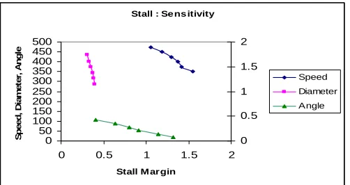
wall losses and other friction losses achieving such high value of efficiency is practically not feasible both in aero space and industrial compressors. Hence the Pareto values of efficiency, stall margin coefficient and Specific area are found to be 0.89, 1.11 and 240m2 respectively. Efficiency and inlet stage specific area are found to be very sensitive to variation in diameter as shown in Figures 4 & 5. It is also found that stall value is greatly sensitive to diameter and speed as shown in Fig6. Also it is found that efficiency is least sensitive to air angle as shown in Fig4.
Conclusion:
In this paper the NSGA technique developed by K deb is described and tested on a three objective non-linear optimization problem of axial compressor stage. The Pareto optimal solution front for the three objective functions has been found successfully, which is not feasible with most of the conventional multi objective algorithms.
Fig 1: Non-Dominant solution zone - Efficiency & Stall
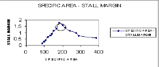
Fig 2: Non dominant solution zone- Specific Area & Efficiency
Efficie ncy: Se ns itivity
0.7 0.75 0.8 0.85 0.9 0.95
0 0.1 0.2 0.3 0.4 0.5 0.6
Flow coe fficie nt, Diam e te r ,Angle
E ff ici enc y 0.86 0.88 0.9 0.92 0.94 0.96 0.98 Flow -Coef f icient
Angle
Diameter
Fig 4 : Sensitivity of Diameter, Angle & Flow-Coeff on Efficiency
Specific Area : Sensitivity
0 100 200 300 400 500
0.1 0.15 0.2 0.25 0.3 0.35 0.4 0.45 0.5 0.55 0.6 0.65 0.7 0.75 0.8 0.85 0.9
Hub-Tip ratio , Diameter
In let S p eci fi c A re a 0 100 200 300 400 500 Hub-Tip ratio Diameter
Fig 5 : Sensitivity of hub-tip ratio and Diameter on Specific Area
Stall : Se ns itivity
0 50 100 150 200 250 300 350 400 450 500
0 0.5 1 1.5 2
Stall M argin
S p ee d , D iam et e r, A n g le 0 0.5 1 1.5 2 Speed Diameter Angle
Fig 6 : Sensitivity of Speed, Diameter & Air angle on Stall
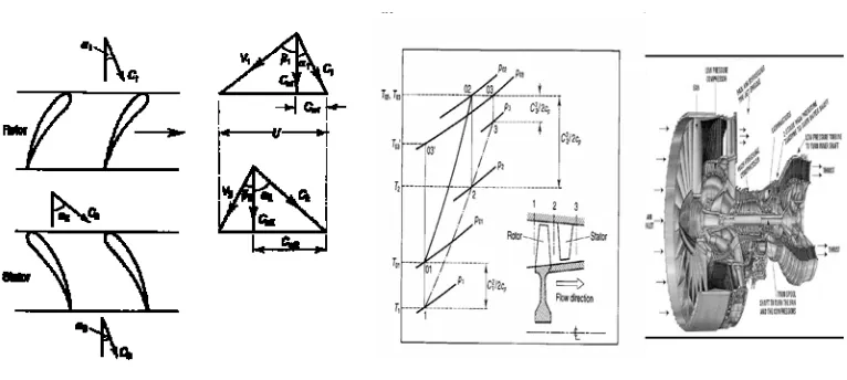
Fig 7 : Velocity Diagrams Fig 8 : T-S diagram
References:
[1] Jin Shik Lim and Myung Kyoon Chung,( March 1989) “Design point optimization of an axial-flow compressor stage”. Int Journal of Heat and fluid flow, 10 (1), pp 48-58.
[2] Goldberg D.E. (1989) “Genetic Algorithms in search, Optimization and Machine learning”, Pearson education edition.
[3] Srinivas.N and Deb.K, (1993) “Multi Objective optimization using non dominated sorting in genetic algorithms”, Technical report, Department of Mechanical Engineering IIT Kanpur, India,
[4] Sehra A, Bettner J & Cohn A, ( 1992) “Design of high performance axial flow compressors for utility gas turbine”, ASME Journal of turbo machinery, 114, pp 227-286.
[5] Koch CC, (1981) “Stalling pressure rise capability of axial flow compressor stages”, ASME Journal of Engineering for power, 103, pp 645-656.
[6] Liebliein S, (September 1959) “Loss and Stall analysis of compressor cascades”, ASME Journal of Basic Engineering, pp 387-400. [7] Smith I H, (1970) “Casing boundary layers in axial flow compressor”, Flow Research on blading edition, Elsevier publishing,. [8] Massardo A and .Satta A, ( 1990) “ Axial flow compressor design optimization part I: pitch line analysis and multi-variable objective
function influence”, ASME Journal of Turbo machinery, 112, pp 399-404.
[9] Rao SS and Guptha R S, (1980) “ Optimum design of Axial flow Gas Turbine stage,: part I : Formulation and analysis of Optimization problem”, ASME Journal of Engineering for power, 102, pp 399-404.
[10] Cohen H, Rogers G F C & Sarvanamatoo H I H, (1989) “Gas Turbine Theory”, Long man Edition, London.
[11] Rajasekaran S and Vijaya Lakshmi Pai G.A., “Neural Networks, Fuzzy Logic & Genetic Algorithms ,Synthesis and Applications”, Prentice-Hall India, Eastern Economy Edition.
[12] Michalewicz Z, “Genetic Algorithms + Data Structures = Evolutionary Programs”, 3rd
extended and revised edition, Springer International Publications.
[13] Goldberg D.E and Richardson J, “Genetic Algorithms with sharing for multimodal function optimization”, In proceedings of the First International conference on Genetic Algorithms and their Applications, pp 41-49.
[14] Kim Y and Walton E.K, (Dec 2006) “Automobile Conformal antenna design using NSGA”, IEEE transactions on Micro waves, Antennas & Propagation, 153( 6), pp 579-582.
[15] 15. Dias Alexandre H.F. and Vasconcelos de Joao A., (March 2002) “Multi Objective Genetic Algorithms applied to solve optimization problems”, IEEE transactions on Magnetics, 38(2), pp 1133-1136.
[16] Chitra C and Subbaraj P, (2010) “A Non dominated sorted Genetic Algorithm for shortest path routing problem”, International journal of computer science, 5, pp 55-63.
[17] Fonesco C.M. and Flemming P.J, (1993) “Genetic Algorithms for multi objective optimization: Formulation, discussion and generalization”, In the proceedings of Fifth International conference on Genetic Algorithms, pp 416-423.