DESIGN & IMPLEMENTATION OF A DATA CENTER
Protap Mollick
1, Amitabh Halder
2, Md. Lutfur Rahman
3,
Md. Rezwan Salmani
41,3
Graduated, Dept. of CSE,
2,4Graduated, Dept. of EEE, American International University
(Bangladesh)
ABSTRACT
A basic Network infrastructure allude to the resources like hardware and software of an entire network that let
network connectivity, communication, operations and control of an enterprise network of a city, industries or
home. Enterprise network infrastructure provides the communication path and services between users,
processes, applications, services and external networks. The main objective of this research paper is to design a
hierarchal enterprise network design of a city with consideration network enterprise edge. Cisco packet Tracer
latest version was used to design & simulate this design. Using Cisco packet tracer we can simulate application
layer protocols, basic routing with RIP, OSPF and EIGRP. Our design consist three locations in Dhaka,
Bangladesh: Data center, Banani Branch & Motijheel Branch.
Keywords: LAN/WAN, OSI Model, Network Switch, Cisco Packet Tracer, Internet Cloud.
I. INTRODUCTİON
The main purpose of an enterprise network is to reduce isolated users and workgroups. All systems should be
capable of communicate and provide and desired information. Additionally, physical systems and devices
should be able to maintain and provide satisfactory performance, reliability and security. Enterprise computing
models are developed for this purpose, facilitating the exploration and improvement of established enterprise
communication protocols and strategies. In scope, an enterprise network may include local and wide area
networks (LAN/WAN), depending on operational and departmental requirements [1]. An enterprise network can
integrate all systems, including Windows and Apple computers and operating systems (OS), UNIX systems,
mainframes and related devices like smartphones and tablets. A tightly integrated enterprise network effectively
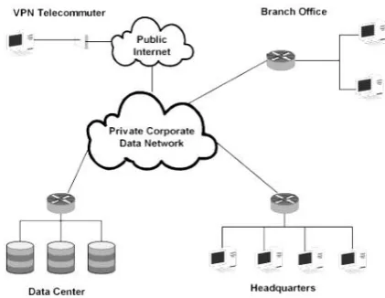
Figure 1: Basic Diagram of an Enterprise Network
A typical Enterprise network includes:
Networking Hardware:
o Routers
o Switches
o LAN cards
o Wireless routers
o Cables
Networking Software:
o Network operations and management
o Operating systems
o Firewall
o Network security applications
Network Services:
o T-1 Line
o DSL
o Satellite
o Wireless protocols
o IP addressing
II. DATA CENTER
A data center is a facility used to house computer systems and associated components, such as
telecommunications and storage systems. It generally includes redundant or backup power supplies, redundant
data communications connections, environmental controls and various security devices. Large data centers are
industrial scale operations using as much electricity as a small town. Data centers have their roots in the huge
computer rooms of the early ages of the computing industry [2]. Early computer systems were complex to
operate and maintain, and required a special environment in which to operate. Many cables were necessary to
connect all the components, and methods to accommodate and organize these were devised, such as standard
power, and had to be cooled to avoid overheating. Security was important because computers were expensive,
and were often used for military purposes.
The main purpose of a data center is running the IT systems applications that handle the core business and
operational data of the organization. Such systems may be proprietary and developed internally by the
organization, or bought from enterprise software vendors. Such common applications are ERP and CRM
systems [3]. A data center may be concerned with just operations architecture or it may provide other services as
well. Data centers are also used for offsite backups. Companies may subscribe to backup services provided by a
data center. This is often used in conjunction with backup tapes. Backups can be taken off servers locally on to
tapes. However, tapes stored on site pose a security threat and are also susceptible to fire and flooding. Larger
companies may also send their backups off site for added security. This can be done by backing up to a data
center. Encrypted backups can be sent over the Internet to another data center where they can be stored securely.
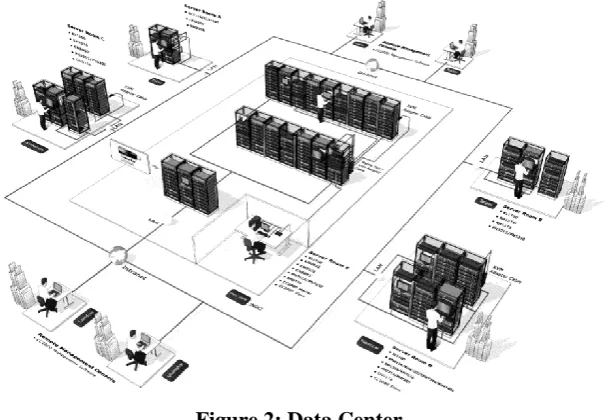
Figure 2: Data Center
III. SWİTCHES: IP ADDRESSES
A network switch is a computer networking device that connects devices together on a computer network, by
using packet switching to receive, process and forward data to the destination device. Unlike less advanced
network hubs, a network switch forwards data only to one or multiple devices that need to receive it, rather than
broadcasting the same data out of each of its ports. A network switch is a multiport network bridge that uses
hardware addresses to process and forward data at the data link layer (layer 2) of the OSI model [4]. Switches
can also process data at the network layer (layer 3) by additionally incorporating routing functionality that most
commonly uses IP addresses to perform packet forwarding; such switches are commonly known as layer-3
switches or multilayer switches. Beside most commonly used Ethernet switches, they exist for various types of
networks, including Fiber Channel, Asynchronous Transfer Mode.
The network switch plays an integral part in most modern Ethernet local area networks (LANs). Mid-to-large
sized LANs contain a number of linked managed switches [5]. Small office/home office applications typically
office/home broadband services such as DSL or cable Internet. In most of these cases, the end-user device
contains a router and components that interface to the particular physical broadband technology [6]. User
devices may also include a telephone interface for Voice over IP (VoIP) protocol.
Figure 3: Network Switch
An Internet Protocol address (IP address) is a numerical label assigned to each device participating in a
computer network that uses the Internet Protocol for communication. An IP address serves two principal
functions: host or network interface identification and location addressing. The designers of the Internet
Protocol defined an IP address as a 32-bit number and this system, known as Internet Protocol Version 4 (IPv4),
is still in use today. However, because of the growth of the Internet and the predicted depletion of available
addresses, a new version of IP , using 128 bits for the address, was developed in 1995.IPv6 was standardized as
RFC 2460 in 1998, and its deployment has been ongoing since the mid-2000s .
IV. DESİGN & SİMULATİON PROTOTYPE
Our Design fully demonstrated by cisco packet tracer. Packet tracer is a program used to illustrate at a basic
level how network work. Packet tracer has two different views- Logical workspace & Physical workspace. It has
two modes of operation-Real time mode & Simulation mode.
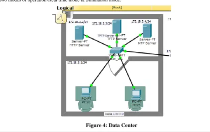
Figure 4 describe Data center model. In this model two pc, three server-HTTP server, TFTP server & NTP
server. One switch model 2980-24TT used to connect all of them. Router 2811 used to connect data center,
branch & internet cloud.Data center configuration is straight forward configuration. There is no VTP here, no
STP, and Use the same EIGRP routing protocol. Configure the serial interface that will connect to the ISP with
the IP address 68.110.171.134/30.
IP for Port:
Serial0/1/168.110.171.133/30
Serial0/1/0 55.55.55.57/30
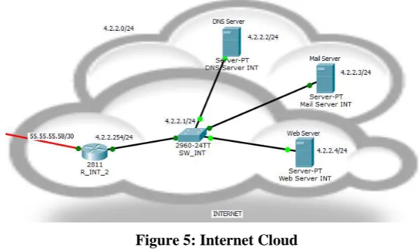
Figure 5: Internet Cloud
Internet Cloud provide users and enterprises with various capabilities to store and process their data in
third-party data centers. It relies on sharing of resources to achieve coherence and economies of scale, similar to a
utility over a network. At the foundation of cloud computing is the broader concept of converged infrastructure
and shared service [7]. Also, straight forward; configure static IPs to the servers and all that. But again, do NOT
configure a routing protocol on the router. Instead, just configure a static route to the 68.110.171.132/30
network going through the ISP router.
Type IP
DNS Server 4.2.2.2/24
Mail Server 4.2.2.3/24
Web Server 4.2.2.4/24
For Figure 6, the right side is motijheel branch & left side is Banani branch .Actually these two branches are just
models including pc, laptop, and Router, Switch and DHCP server. All these locations are connected through a
frame relay switch. The Data Center is connected to the ISP to get to the simulated Internet (it is a 4.2.2.0/24
network).
IV. IP CONFİGURATİON USED İN DESİGN
Switches IP Addresses
Configure IP addresses for the switches (which will be in VLAN 1, subnet 172.16.1.0/24). Their default
gateway will be 172.16.1.254
VTP & VLANS
Configure the ports connected between the switches to trunk ports. Create VLANs 30 and 40 on one switch,
name them DATA1 and DATA2 respectively. Configure the VTP domain "BB" on the switch.
VLAN Name Status Ports
10 VOICE_WB active
30 DATA1_WB active Fa0/5, Fa0/6
40 DATA2_WB active Fa0/2, Fa0/3, Fa0/4, Fa0/7
STP & Router
Configure its Fast Ethernet port on the VLAN 40 subnet and configure the port on the switch on VLAN 40.
ip dhcp pool FORVLAN40
network 172.16.40.0 255.255.255.0
default-router 172.16.40.254
dns-server 4.2.2.2
ip dhcp pool FORVLAN10_VOICE
network 172.16.10.0 255.255.255.0
default-router 172.16.10.254
option 150 ip 172.16.10.254
V. CONCLUSION
The process of designing a good network requires concerted efforts by network designers and technicians, who
identify network requirements and select the best solutions to meet the needs of a business. The four
fundamental technical requirements of network design are scalability, availability, security, and Manageability.
Our Purpose is to just design an enterprise network only for software based not practically. The main Purpose of
this paper is:
Enterprise network design overview.
The benefits of enterprise network.
New design methodology
Besides advantages there are some limitations of enterprise network like:
Encryption
Everything in HTTP[S]
NAT, proxies, tunneling
Carrier-grade NAT/IPv4 islands
Lack of knowledge of policy and assets
Legal restrictions
REFERENCES
[1] K. Sohrabi and G. J. Pottie, "Performance of a novel self-organization protocol for wireless and
enterprise network", Proc. IEEE 50th Vehicular Technology Conf., pp.1222 -1226 1999
[2] W. R. Heinzelman, A. Chandrakasan, and H. Balakrishnan, "Design and optimization of a data center",
Proc. Hawaii Int. Conf. Systems Sciences, pp.3005 -3014 2000
[3] A. Woo and D. Culler, "A transmission control scheme for data center", Proc. ACM/IEEE Int. Conf.
Mobile Computing and Networking, pp.221 -235 2001
[4] V. Bharghavan, A. Demers, S. Shenker, and L. Zhang,”AACAW: A Internet access protocol for
wireless lans", Proc. ACM SIGCOMM, pp.212 -225,1994
[5] J. C. Haartsen, "The Switching system", IEEE Pers. Commun. Mag., pp.28 -36 2000
[6] Y.-C. Tseng, C.-S. Hsu, and T.-Y. Hsieh, " IEEE 802.11-based multi-hop Switching system", Proc.
IEEE INFOCOM, pp.200 -209 2002
[7] S. Xu and T. Saadawi, "Internet computing protocol in multihop wireless ad hoc networks?", IEEE