STUDY OF SURFACE MORPHOLOGIES AND
DEFECTS OF FRICTION STIR WELDED AA6101
ALUMINUM ALLOY
Sachindra Shankar¹, Dharmendra Kumar Prasad
2, Shabbir Ali
3,
Ratnesh Kumar
4, Somnath Chattopadhyaya
51,2,3
M.Tech Student,
4Research Scholar,
5Associate Professor, Department of Mechanical
Engineering, Indian School of Mines, Dhanbad, (India)
ABSTRACT
This paper deals with the lap joint of similar AA6101 plates of thickness 5mm and 3mm respectively was
produced by friction stir welding technique with a plane conical tool using the various process parameters such
as rotational speed and welding speed. Three levels of parameters have been chosen 355 rpm, 500 rpm and 710
rpm rotational speeds and 16mm/min, 25mm/min, 40mm/min traverse speeds. This paper also deals with the
effect of rotational speeds and plunging action and the problem or defect on the quality of the weld.
Keywords: aluminum alloy, friction stir welding, lap- joint, rotational speed, welding speed
I. INTRODUCTION
Friction stir welding (FSW) is a process which does not require any filler material for joining of material. It uses
a rotating tool plunges into the workpiece with movement along the joint line invented in 1991 in the UK [1],
see fig1. Since FSW is a solid-state joining process, therefore no melting of the base material required. This
method can be used to produce butt joints, lap joints and also T joints of same or dissimilar alloys [2-6]. This
method is best suitable for the fabrication of aluminum alloy which when fabricated with the conventional
fusion welding process results in problems like porosity, distortion because of its high thermal conductivity and
solidification shrinkage. Aluminum alloy 6101 used in various industry with magnesium and silicon as the main
alloying element. AA6101 alloy found their application in aerospace industry, marine fittings, hardware,
electrical connectors and bike frames etc. AA6101 aluminum alloy has good formability, weldability,
machinability, and corrosion resistance. Properties of the material are
Table1: component (% by weight) and of AA6101 alloy
Component Symbol Wt (%)
Chromium Cr 0.1
Copper Cu 0.5
Magnesium Mg 0.6
Manganese Mn 0.03
Iron Fe 0.5
Silicon Si 0.5
Zinc Zn 0.1
Boron B 0.06
Aluminum
Al rest
Table2: mechanical property of AA6101
Mechanical property value
Tensile strength 97MPa
Hardness Brinell 71
A lot of papers are focused on the butt joint of similar and dissimilar aluminum alloy but very few papers focus
on the lap joint of aluminum alloy. There is no effect of length of the probe on the mechanical properties of
joints under static load but it depends on the width of the weld at the interface between the materials [7]. For,
this reason the whole experiment performed with a welding interface of 3cm.
Kittipong Kimapong et al. studied about the lap joint of AA5083 Aluminum Alloy and SS400 Steel and
observed that with increasing the rotational speed of the tool the shear load capacity of the weld decreases
because of the inter-metallic compound formed at the area of joining between aluminum and steel [8]. A.
Elrefaey et al. studied the effect of pin depth and rotational speed of lap joint of aluminum and steel plate [9]. G.
M. D. Cantin et al. analyzed. The microstructure and mechanical properties of welds using a conventional
pin-type probe of AA5083-o al alloy [10]. H. Bisadi et al. also studied the effect of process parameter on
microstructure and mechanical property of AA5083 Al alloy and observed that the nugget area had the best
grain size and also micro-hardness and also observed that the best properties were achieved at specific rotational
and welding speed [11]. K. S. Miller et al. investigated the interface lifting problem which results in the weaker
weld joint section during friction stir welding lap joint and concluded that the interface lifting problem can be
solved by welding at high rotational speed and low traverse speed [12]. S.Babu et al. analyzed the
microstructure and mechanical Properties of Friction Stir lap welded AA2014 aluminum alloy and concluded
that the hook geometry is the main culprit in case of friction stir lap welds, and also compared this lap welds
with the riveted joints and found that the FSW lap joint is much stronger than the riveted joint [13]. G.Buffa et
Chandresh V studied the effect of four different type of pin profile and concluded that the square pin profile
gives better result and defect free surface than the other three tool pin [15].
II. EXPERIMENTAL PROCEDURE
The material selected for this experiments are plates of aluminum alloy having different thickness of 3mm and
5mm respectively. The plates are cut into dimensions of 100mmx50mm each. The whole the experiment
performed on a vertical milling machine. Since we used the same type of material, therefore there is no any
worry of placement of the plates on retreating or advancing side according to their hardness. Specially designed
tool used in this experiment according to the arbor of the vertical milling machine. The material of the tool is
SS410. A non-consumable high- speed steel tool was employed for welding 6101 aluminum alloy having the
shoulder diameter of 30mm and the tool has a probe (tool pin).The tool has the plane conical shaped probe.
Probe diameter varies from 5mm at the top to 3mm at the bottom.The clamping set-up designed according to
the condition of the bed of vertical milling machine.
III. RESULTS AND DISCUSSION
3.1 The effect of rotational speeds and welding speeds on the surface morphologies of weld
The lap joint of AA 6101 aluminum alloy performed at different rotational speeds and welding speeds. The
results were analyzed and we obtained some results on the basis of experiments performed. In the images the
meanings of the symbols are:
A – Advancing side
R – Retreating side
a/b – Rotational speeds/welding speeds
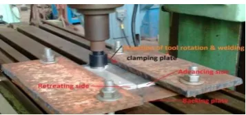
If the direction of tangent on any of plates in the direction of rotation of tool and welding direction are same
then it is known as advancing side and if the direction of tangent of any of plates in the direction of rotation of
tool and welding directions are opposite then it is known as retreating side as shown in fig1.
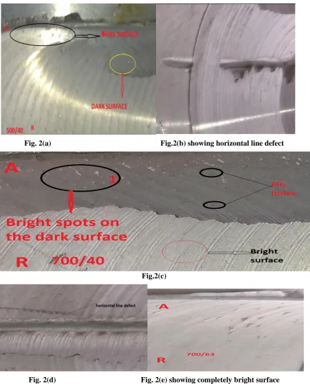
During the analysis, we found a shiny and wide surface along the advancing side of the plate and a dark surface
along the retreating side of the plate when welding was performed at the rotational speed of 500 Rpm and
welding speed of 40 mm/min as shown in fig 2(a). The result was completely opposite that the dark surface was
on the advancing side and shiny surface was on the retreating side of plate and also found some bright spot and
pin holes on the dark surface of retreating side of plate when welding performed at a rotational speed of 710rpm
and bed or welding speed of 40mm/min as shown in fig 2(c).Some defects were also found on the weld surface
one of them was horizontal line defect as given in fig 2(b) and fig 2(d) The possible cause of horizontal line
Fig. 2(a) Fig.2(b) showing horizontal line defect
Fig.2(c)
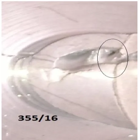
Fig. 2(f) showing hole defect and verticle line defect
are the combination of high rotational speed and welding speed. A defect, also known as hole defect and vertical
line defect also present on the surface of one of the sample as shown in fig 2(f).The main reason of this defect
was high plunging action by the tool on the surface of the plate to be join. If the plunging action will be too
high, it will result in the breaking of the upper plate due to complete removal of material as a chip from the
upper plate of the material.
IV.
CONCLUSION
So from the experimental analysis of lap joint of the AA6101 aluminum alloy, we may conclude that
1. Lap joint of the AA6101 aluminum alloy was successfully produced by friction stir welding.
2. Plunging action should be kept at optimum value otherwise, it will lead to vertical line defects and hole
defects.
3. The rotational and welding speeds should be kept at optimum value otherwise; it will result in horizontal line
defect.
REFERENCES
[1] Thomas WM, et al. Friction Stir Butt Welding, International Patent Appl. PCT/GB92/02203 and GB
Patent Appl. 1998. No. 9125978.8, December.
[2] M.J. Brooker, A.J.M Van Deudekom, S.W. Kallee, P.D. Sketchley. Applying friction stir welding to airane
5 main motor thrust frame, Proceeding of the European Conference on Spacecraft Structures, Materials
and Mechanical Testing, Noordwijk, The Netherlands. 2000. 29 November - 1 December. pp. 507-511.
[3] M.G. Dawes, S.A. Karger, T.L. Dickerson, J. Przyoatek. Strength and fracture toughness of friction stir
[4] S.W. Williams .Welding of airframes using friction stir. 2001. Air and Space Europe. 3: 64-66.
[5] Krishnan KN. On the formation of onion rings in friction stir weld. Material Science Eng. 2002. 246-251.
[6] W. M. Thomas, E. D. Nicholas, S.D. Smith. In: S.K. Das, J.G.Kaufman, T.J. Lienert (Eds.), Aluminum
2001-proceedings of the TMS Aluminum Automotive and Joining Sessions, TMS. 2001. p. 213.
[7] K. Krasnowski, Fatigue and static properties of friction stir welded aluminum alloy 6082 lap joints using
triflute-type and smooth tool. in archives of metallurgy and materials. 2014. vol 59.
[8] Kittipong Kimapong*, and Takehiko Watanabe. “Lap joint of AA5083 aluminum alloy and SS400 Steel
by Friction stir welding”.Materials transactions. 2005. 835– 841.
[9] A. Elrefaey, M. Gouda, M. Takahashi, and K. Ikeuchi. Characterizations of aluminum/Steel lap Joint by
Friction stir welding. ASM international. 2004.14:10-17.
[10] G. M. D. Cantin, S. A. David, W. M. Thomas, E. Lara-Curzio, and S. S Babu. Friction skew stir welding
of lap joints in 5083–0 aluminum, Science and technology of Welding and Joining. 2005. 268-280.
[11] H. Bisadi, M. Tour, A. Tavakoli. The Influence of Process Parameters on Microstructure and Mechanical
Properties of Friction Stir Welded Al 5083 Alloy Lap Joint. American journal of material science. 2011.
93-97.
[12] K. S. Miller, C. R. Tolle, D. E. Clark, C. I. Nichol, T. R. McJunkin, H. B. Smartt. The investigation into
Interface Lifting within FSW Lap Welds. Trends in welding Research, 8th International conference. 2008.
INL/CON-08-14900.
[13] S. Babu, G.D. Janaki Ram1, P.V. Venkitakrishnan, G. Madhusudhan Reddy and K. Prasad Rao.
Microstructure and Mechanical Properties of Friction Stir Lap Welded Aluminum Alloy AA2014 J. Mater.
Sci. Technol. 2011. 414–426.
[14] G. Buffa, L. Fratini. Numerical Analysis of Friction Stir Welding of Stainless Steel Lap Joints.
International conference on competitive manufacturing. 2013.
[15] Patel Chandresh V. Effect of Tool pin Profile on Aluminum alloy using FSW for optimum results by
finding optimum Parameters | ISSN: 2321-9939. International journal of Engineering, development and