San Jose State University
SJSU ScholarWorks
Master's Theses Master's Theses and Graduate Research
Spring 2012
Scaling CUDA for Distributed Heterogeneous
Processors
Siu Kwan Lam
San Jose State University
Follow this and additional works at:https://scholarworks.sjsu.edu/etd_theses
This Thesis is brought to you for free and open access by the Master's Theses and Graduate Research at SJSU ScholarWorks. It has been accepted for inclusion in Master's Theses by an authorized administrator of SJSU ScholarWorks. For more information, please [email protected]. Recommended Citation
Lam, Siu Kwan, "Scaling CUDA for Distributed Heterogeneous Processors" (2012).Master's Theses. 4143. DOI: https://doi.org/10.31979/etd.mnnq-tj8b
SCALING CUDA FOR DISTRIBUTED HETEROGENEOUS PROCESSORS
A Thesis
Presented to
The Faculty of Department of Computer Engineering
San José State University
In Partial Fulfillment
of the Requirements for the Degree
Master of Science
by
Siu Kwan Lam
© 2012
Siu Kwan Lam
The Designated Thesis Committee Approves the Thesis Titled
SCALING CUDA FOR DISTRIBUTED HETEROGENEOUS PROCESSORS
by
Siu Kwan Lam
APPROVED FOR THE DEPARTMENT OF COMPUTER ENGINEERING
SAN JOSÉ STATE UNIVERSITY
May 2012
Dr. Donald Hung Department of Computer Engineering
Dr. Xiao Su Department of Computer Engineering
ABSTRACT
SCALING CUDA FOR DISTRIBUTED HETEROGENEOUS PROCESSORS
by Siu Kwan Lam
The mainstream acceptance of heterogeneous computing and cloud computing is prompting a future of distributed heterogeneous systems. With current software development tools, programming such complex systems is difficult and requires an extensive knowledge of network and processor architectures. Providing an abstraction of the underlying network, message-passing interface (MPI) has been the standard tool for developing distributed applications in the high performance community. The problem of MPI lies with its message-passing model, which is less expressive than the
shared-memory model. Development of heterogeneous programming tools, such as OpenCL, has only begun recently. This thesis presentsPhalanx, a framework that extends the virtual architecture of CUDA for distributed heterogeneous systems. Using MPI, Phalanx transparently handles intercommunication among distributed nodes. By using the shared-memory model, Phalanx simplifies the development of distributed applications without sacrificing the advantages of MPI. In one of the case studies, Phalanx achieves 28×speedup compared with serial execution on a Core-i7 processor.
ACKNOWLEDGEMENTS
I would like to offer my gratitude to my advisor Dr. Donald Hung, who has provided enormous support to my thesis. I would also like to thank Dr. Xiao Su, who has
encouraged my interest in research. In addition, this thesis is supported in part by the SJSU Award for Research, Scholarship, or Creative Activity (SJSU RSCA grant).
Contents
1 Introduction 1 1.1 Levels of Parallelism . . . 2 1.1.1 Instruction-Level Parallelism . . . 2 1.1.2 Data-Level Parallelism . . . 3 1.1.3 Task-Level Parallelism . . . 3 1.2 Parallel Architectures . . . 3 1.2.1 SIMD Processor . . . 4 1.2.2 Multicore . . . 4 1.2.3 Manycore . . . 4 1.2.4 Distributed Systems . . . 51.3 Challenges in Developing Distributed Applications . . . 6
1.3.1 Shared-Memory Model Versus Message-Passing Model . . . 6
1.4 Related Works . . . 8
1.4.1 MCUDA . . . 8
1.4.2 Ocelot . . . 9
1.4.3 OpenCL . . . 9
1.5 Project Goals and Thesis Organization . . . 9
2 Phalanx Overview 11 2.1 CUDA as a Unified Virtual Architecture . . . 11
2.1.1 Thread Hierarchy . . . 11
2.1.2 Memory Hierarchy . . . 12
2.1.3 Streaming Multiprocessors . . . 13
2.1.4 Mapping CUDA to Distributed Systems . . . 13
2.2 Compiling CUDA Kernels for Distributed Systems . . . 14
2.3 Emulation of CUDA . . . 14
2.4 Design for Heterogeneity . . . 15
2.5 The Workflow of Phalanx . . . 16
3 The PTX-to-LLVM Compiler 18 3.1 Execution Model of PTX . . . 18
3.1.1 Branching and Warp Divergence . . . 19
3.1.2 Thread Barrier . . . 19
3.2 Refined Execution Model . . . 20
3.3 Handling Register and Memory States . . . 22
3.3.1 Registers . . . 22
3.3.2 Memory . . . 24
4 The Runtime System 26
4.1 Remote Kernel Manager . . . 27
4.2 Warp Scheduler . . . 30 4.3 PTX Emulator . . . 32 4.3.1 Branch Instructions . . . 32 4.3.2 Memory Instructions . . . 32 4.3.3 Exit Instruction . . . 33 4.3.4 Barrier Instruction . . . 33 4.4 Remote Requests . . . 33
5 The Memory System 36 5.1 Memory Operations . . . 36
5.1.1 Global Memory . . . 37
5.1.2 Shared Memory . . . 37
5.2 Handling Heterogeneous Data Model . . . 38
5.3 Memory Consistency . . . 38
5.4 Optimizing Global Memory Requests . . . 39
5.4.1 Principle of Balance . . . 39
5.4.2 Caching . . . 40
5.4.3 Transaction Size . . . 40
6 Case Study: Matrix Multiplication 42 6.1 Application Background . . . 42
6.2 Using Shared Memory . . . 43
6.3 Implementation . . . 44
6.4 Benchmark . . . 44
6.5 Performance Analysis . . . 44
7 Case Study: NBody 48 7.1 Application Background . . . 48
7.2 Implementation . . . 49
7.3 Benchmark . . . 49
7.4 Performance Analysis . . . 51
8 Conclusion and Future Works 52 Bibliography 54 A Source Listing for Case Studies 56 A.1 Matrix Multiplication Case Study . . . 56
List of Figures
2.1.1 CUDA thread hierarchy . . . 12
2.1.2 CUDA memory hierarchy . . . 12
2.1.3 Logical structure of NVIDIA streaming multiprocessors. . . 13
2.1.4 Comparison of a GPU and a distributed system. . . 14
2.5.1 Phalanx workflow. . . 17
3.1.1 Execution of a warp. . . 19
3.2.1 Sample separation of PTX kernel entry into subkernels. . . 20
3.2.2 Control-flow graph of a sample subkernel function in LLVM-IR. . . 23
4.0.1 System diagram of the runtime system. . . 26
4.4.1 Sequence diagram of remote requests. . . 35
6.1.1 Illustrating matrix multiplication. . . 43
6.4.1 Matrix multiplication benchmark. . . 45
6.5.1 NBody benchmark: achieved compute throughput versus matrix size. . . . 46
7.3.1 NBody benchmark: execution time. . . 50
7.3.2 NBody benchmark: speedup. . . 50
Chapter 1
Introduction
This thesis presents a new approach to programming a distributed heterogeneous system. Traditionally, high performance distributed applications use message-passing interface (MPI) for intercommunication among nodes. The difficulty to program MPI applications lies with its use of the message-passing model, which is less expressive than the
shared-memory model. The new approach does not aim to replace MPI, but to hide all MPI specifics from the programmers. Therefore, programmers can program efficiently using the shared-memory model with the advantages of MPI.
This thesis focuses on the development of thePhalanxframework, which compiles compute unified device architecture (CUDA) kernels for parallel execution on multicore processors and distributed heterogeneous systems. Phalanx extends the virtual
architecture of CUDA for MPI-based distributed applications. Together with the
on-demand and dynamic allocation of compute resources provided by cloud computing, Phalanx allows CUDA kernels to scale from a manycore GPU to a massive distributed system consisting of hundreds of processors.
This chapter provides a general background for the discussion of Phalanx. In the rest of this chapter, Sections 1.1 and 1.2 provide a brief discussion of different levels of parallelism and parallel architectures, respectively. Section 1.3 discusses the challenges faced by distributed application programmers. Section 1.4 presents several related projects that are leading the research in heterogeneous computing. Finally, Section 1.5 states the goals of this project and explains the organization of this thesis.
1.1 Levels of Parallelism
Traditionally, software developers have relied on the advances in hardware for higher performance. For years, the processor industry merely pushed for a higher clock rate to increase computational performance until thepower wallwas reached. The power wall represents a physical limitation of the CMOS technology. Power consumption increases exponentially with an increment in clock rate [1]. Since power is dissipated as heat, the temperature of a processor would rise to an unbearable level. To further improve the performance without increasing clock rate, processor designers began to exploit various forms of parallelism in computer programs.
The following subsections describe three levels of parallelism. The order of presentation indicates a growing reliance on programmer effort. The first level of parallelism can be automatically discovered by compilers and processors. The last level of parallelism requires explicit control by the programmer.
1.1.1 Instruction-Level Parallelism
Withinstruction-level parallelism(ILP), a processor executes data-independent
instructions in a concurrent fashion. Patterson and Hennessy [2] described the following techniques. Pipeliningallows data-independent instructions to overlap in different stages of a processor datapath. Superscalarimplements multiple datapaths for data-independent instructions to execute in parallel. A more complex implementation usesout-of-order
execution, which reorders the sequence of instructions to reduce data dependency among consecutive instructions.
ILP is limited and further exploitation requires overly complicated logic in the processor. With an exponential growth of transistor count in processors predicted by Moore’s Law, a more efficient use of transistors is needed [2].
1.1.2 Data-Level Parallelism
Withdata-level parallelism(DLP), a processor exploits the scenario where the same instruction operates on a wide data set [3]. Such a scenario occurs frequently in loops where the same operation repeats for every element in an array. Processors usually implement vector instructions for DLP. Some compilers can automatically generate vector instructions from high-level source code, but explicit vectorization by a programmer will typically yield higher performance.
1.1.3 Task-Level Parallelism
Task-level parallelism(TLP) is a coarsened version of ILP. Independent computing tasks can be executed in parallel. A task is usually represented by a thread. Each thread has an independent instruction stream. A multicore processor executes multiple threads in different processor cores. Multithreaded processors, such as Oracle UltraSparc and Intel Hyperthread processors, overlap instructions from multiple threads within a single processor by sharing processor resources [2]. When a thread engages in a long memory operation using the load-store units, other threads can execute in parallel using the arithmetic units.
1.2 Parallel Architectures
Consisting of a combination of ILP, DLP and TLP, a modern parallel architecture is both massive and complex. As noted by Gebali [3], it is difficult to precisely categorize
parallel architectures using Flynn’s Taxonomy, which divides computer systems according to the organization of instruction and data streams. Some parallel architectures exist on a single silicon die. Some exist as a group of networked machines. The following
1.2.1 SIMD Processor
single-instruction multiple-data (SIMD) processors are common in commodity computers because adding support for SIMD instructions to scalar processors is relatively easy [4, 3]. Almost all modern Intel processors contain the MMX and SSE multimedia extensions, supporting up to 128-bits of vector data. Intel recently released the SandyBridge architecture withadvanced vector execution(AVX), extending the vector width to 256-bits.
Pattern and Hennessy [4] explained how SIMD instructions can reduce the time to fetch, decode, and execute. A SIMD instruction performs multiple parallel operations in one cycle, replacing 2-8 scalar instructions. With 256-bit vectors, a single SIMD
instruction can execute 8 parallel single precision floating-point operations. 1.2.2 Multicore
Multicore processors execute multiple threads in different execution cores. Explicit task division is required to use the capability of multicore processors. Determining the granularity of tasks is not easy. If a program has a fine-grain TLP, the overhead due to communication and synchronization could affect the performance of the program
significantly. Some on-going projects aim to perform automatic scheduling of tasks. For instance,StreamIT [5] is a domain-specific language that allows programmers to describe the data-flow of a program. Its compiler converts data-flow descriptions into parallel tasks. However, the difference in the programming model creates a steep learning curve for programmers.
1.2.3 Manycore
Manycorearchitectures, such as NVIDIA CUDA, combine DLP and TLP in a massive manner. Using thousands of parallel threads, a NVIDIA CUDA-enabledgraphical processing unit(GPU) acts as an accelerator for the CPU. In the past, the design of GPUs
exploited the high degree of DLP in computer vision applications. With the introduction of CUDA, GPUs can now support general-purpose applications. More applications can benefit from the high computation and memory throughput of these general-purpose GPUs (GPGPUs).
GPUs execute specially compiled programs calledkernels. To invoke a CUDA kernel, the CPU transfers the kernel and all depending data to the GPU. During the kernel execution, the CPU is free to compute other tasks. When the kernel computation has been completed, the CPU retrieves the results from the memory on the GPU.
1.2.4 Distributed Systems
Gebali [3] described two kinds of distributed systems. Aclustersystem consists of interconnected computers over alocal-area network (LAN). These computers are often identical. A computegridconsists of interconnected computers over awide-area network
(WAN). Computers in a grid are often heterogeneous, consisting of different processor architectures, operating systems, and data models. Distributed systems are suitable for coarse grain parallelism because the communication overhead can be significant.
Communication among nodes in a distributed system usually uses message-passing interface (MPI). MPI [6] is a standardizedapplication programming interface(API) that provides a high performance messaging facility for high level languages. It is scalable. It supports parallel computing in shared-memory multiprocessors, clusters and massive compute grids. It is also portable. OpenMPI [7, 8] is a notable open-source effort that combines technologies from multiple MPI implementations and strongly support for heterogeneous processors, operating systems (OSs), and networks.
Cloud computing is a form of grid computing [3]. Amazon Elastic Compute Cloud
(EC2)1supports both CPU and GPU instances. Users can instantly deploy a
heterogeneous compute grid with no installation cost. Cloud services supply compute 1http://aws.amazon.com/ec2/
resources as utilities, so that users pay only for their usage. Cloud computing provides a new possibility for affordable supercomputing.
1.3 Challenges in Developing Distributed Applications
Computing resources are available for building distributed heterogeneous systems at low costs, but challenges remain in the software development for such systems. A major problem lies in the programming model. Programmers are familiar with the
shared-memory model, which is used by most of the popular programming languages, including C/C++, JAVA, and FORTRAN. MPI uses the message-passing model, which
expresses data movements in messaging events, such as send and receive. The following presents a comparison between the shared-memory model and the message-passing model.
1.3.1 Shared-Memory Model Versus Message-Passing Model
The shared-memory model and the message-passing model each have advantages for different parallel programming patterns. For complex and dynamic data movements, the shared-memory model is more expressive, whereas the message-passing model requires custom message composition to describe each data movement. For synchronization, the shared-memory model requires explicit control through the use of barriers and memory fences, whereas synchronization in the message-passing model is implicitly defined by simple send and receive events.
Listing 1.1: A C-like pseudocode demonstrating a parallel counter increment using the shared-memory model. 1 i n t s h a r e d C o u n t e r = 0 ; / / s h a r e d by a l l t h r e a d s 2 i n t l o c a l V a r ; / / l o c a l t o t h r e a d 3 / / o b t a i n m u t e x l o c k on s h a r e d C o u n t e r 4 l o c k ( s h a r e d C o u n t e r ) ; 5 l o c a l V a r = s h a r e d C o u n t e r ; / / r e a d s h a r e d C o u n t e r 6 l o c a l V a r += 1 ; / / i n c r e m e n t l o c a l d a t a 7 s h a r e d C o u n t e r = l o c a l V a r ; / / m o d i f y s h a r e d d a t a 8 / / r e l e a s e m u t e x l o c k on s h a r e d C o u n t e r
9 u n l o c k ( s h a r e d C o u n t e r ) ; 10 / / e n s u r e a l l t h r e a d s s e e t h e new v a l u e 11 m e m o r y f e n c e ( ) ;
Listing 1.2: A C-like pseudocode demonstrating a parallel counter increment using the message-passing model. 1 / / a s s u m e a 10 n o d e s r i n g 2 / / t h e h o s t n o d e i s node−0 3 / / t h e l a s t n o d e i s node−9 4 i n t c o u n t e r ; 5 i f ( nodeID ==0) {/ / t h e h o s t n o d e 6 c o u n t e r = 1 ; 7 s e n d ( c o u n t e r , 1 ) ; / / s e n d s t o node−1 8 r e c v ( c o u n t e r , 9 ) ; / / r e c e i v e f r o m node−9 9 }e l s e{/ / o t h e r w o r k e r n o d e s 10 r e c v ( c o u n t e r , ( nodeID−1) %10) ; / / r e c e i v e f r o m p r e v i o u s n o d e 11 c o u n t + = 1 ; 12 s e n d ( c o u n t , ( nodeID + 1 ) %10) ; / / s e n d t o t h e n e x t n o d e 13 }
Listing 1.1 shows a pseudocode for performing counter increments in parallel fashion using the shared-memory model. Explicit use of locks and memory fences is necessary to ensure data consistency. Listing 1.2 shows a similar pseudocode using the
memory-passing model. Unlike the shared-memory model, each node has a separate address-space. The nodes form a ring topology. Each node adds to thecountervariable and passes the variable to the next node.
Kumaret al. [9] claimed that the divide-and-conqueur pattern is easier to map onto the shared-memory model. The message-passing model offers a better task isolation and easier validation. Despite the shared-memory model being more expressive, the
error-prone nature of explicit synchronization and unclear task isolation can cause difficulty in software verification and maintenance. The message-passing model is more suitable for the following reasons. First, tasks are naturally isolated in different processes. Second, race conditions are impossible with the separation of address-space.
performance-critical situations. How long a synchronous receive event must wait for its corresponding send event is unclear. The processor remains idle when waiting for message events. In MPI, asynchronous messaging can reduce idle time by overlapping computations, but it requires explicit synchronization and management. Asynchronous messaging increases the overall complexity of a program.
While caching in the shared-memory model is often automatic, the message-passing model requires programmers to adjust program design and message composition to account for data locality. Due to the overhead of each message, coalescing data transfer can reduce the number of messages, thereby improving network utilization. The network bandwidth is often lower than the computing throughput. Without efficient use of network resources, a message-passing application can easily become I/O bounded.
1.4 Related Works
This section briefly introduces three related projects that are leading the research in heterogeneous computing.
1.4.1 MCUDA
Stratton et al. [10] described a source-to-source compilation framework called MCUDA for translating CUDA-C source code into multithreaded ANSI-C programs. MCUDA decomposes CUDA kernels at synchronization points and encloses the resulting
subkernels with a loop that iterates over all threads. Each subkernel loop can be compiled into a SIMD loop for efficient execution on CPUs.
In contrast, Phalanx compiles at the PTX-level. Any high level language that can be lowered to PTX can be used in Phalanx.
1.4.2 Ocelot
Ocelot2is a large research project from the School of Electrical and Computer
Engineering, Georgia Institute of Technology. Diamoset al. [11] described Ocelot as a dynamic compilation framework for CUDA and an opensource CUDA runtime. It can just-in-time recompile CUDA kernels for execution on NVIDIA GPUs, AMD GPUs and x86 CPUs. Ocelot uses a series of complex analysis to transform PTX for CPU execution. Ocelot facilitates the research of GPU computing by providing debugging, analysis and monitoring frameworks for CUDA kernels. A recently added feature allows remote machines to emulate GPUs. Comparing with Ocelot, Phalanx distributes the computation of a kernel across multiple machines. Ocelot offloads a kernel execution to a remote machine.
1.4.3 OpenCL
OpenCL (open computing language)3is a parallel programming language that focuses in portability across heterogeneous devices. With OpenCL, programmers can write portable parallel programs. OpenCL programs execute on handheld devices, personal computers, and servers. Khronos Group maintains an open standard for OpenCL. Hardware support relies on individual vendors to provide implementations for specific devices.
Phalanx can execute program written in OpenCL by lowering OpenCL to PTX. NVIDIA officially supports the compilation of OpenCL to PTX4.
1.5 Project Goals and Thesis Organization
Heterogeneous computing is an on-going research. Phalanx introduces a new approach by combining CUDA and MPI. Phalanx aims to simplify the application development for distributed heterogeneous systems, so that individuals and businesses can easily leverage
2http://gpuocelot.gatech.edu 3http://www.khronos.org/opencl/ 4http://developer.nvidia.com/opencl
the highly available and affordable compute resources provided by cloud services. Phalanx compiles CUDA kernels for executing on distributed systems. Heterogeneous support is currently limited to different CPU architectures. GPU support is possible, but it is left for future works. Phalanx achieves its goal by implementing:
• a shared-memory model for programming distributed systems;
• a unified virtual architecture that scales across heterogeneous systems; and, • a runtime system that implements the unified virtual architecture on distributed
systems.
The rest of this thesis discusses the Phalanx framework in details. Providing an overall description of Phalanx, Chapter 2 introduces its functions, major components and the development tasks. Chapters 3, 4 and 5 explain the details of the PTX-to-LLVM compiler, the runtime system and the memory system, respectively. Chapters 6 and 7 present two application case studies. Finally, Chapter 8 concludes the thesis.
Chapter 2
Phalanx Overview
The Phalanx framework uses CUDA as a unified virtual architecture. It consists of the following components:
1. a compiler for translating CUDA kernel definitions for CPU backends; 2. a runtime system that emulates CUDA for distributed systems; and,
3. a memory system that handles intercommunication among nodes in the distributed systems.
These components are discussed in details in the following chapters. Chapter 3 discusses the PTX-to-LLVM compiler. Chapter 4 discusses the runtime system. The memory system, which is part of the runtime system, is discussed separately in Chapter 5. 2.1 CUDA as a Unified Virtual Architecture
Phalanx extends CUDA for distributed heterogeneous systems. CUDA is a proprietary virtual architecture and programming model for NVIDIA GPGPUs (general-purpose graphical processing units). CUDA combines the expressiveness of the shared-memory model and the clear isolation of the message-passing model through its thread and memory hierarchies.
2.1.1 Thread Hierarchy
CUDA has a thread hierarchy that facilitates the decomposition of an application into a set of parallel tasks. Figure2.1.2illustrates the thread hierarchy. When a CUDAkernel
launches, agridis allocated in the GPU context. The relation between a kernel and a grid is similar to the relation between a program and a process. A grid is an executing instance
Thread Block
2D grid of blocks 3D block of threads
Grid
Figure 2.1.1: CUDA thread hierarchy [12].
Block Grid 0 Thread
Local Memory Shared Memory Global Memory
per thread per block per GPU
Grid 1
Figure 2.1.2: CUDA memory hierarchy and its relation with the thread hierarchy [12].
of a kernel. A grid consists a set ofblocks, also known asCooperative Threads Arrays
(CTAs). Each block defines an independent task that executes in TLP fashion.
Intercommunication among blocks is not possible because the execution order for blocks is not strictly defined. Threadsin a block can cooperate in DLP fashion.
Each thread executes the kernel once. Two new keywords,blockIdxandthreadIdx, uniquely identify each block in a grid and each thread in a block. These identifications are generally used for task division, allowing the kernel to assign different tasks for different threads.
2.1.2 Memory Hierarchy
The CUDA memory hierarchy corresponds to the thread hierarchy as depicted in Figure 2.1.2. Each thread has access to a privatelocal memoryfor storing large data that does not
core core core core
core core core core
Shared Memory Streaming Multiprocessor
Figure 2.1.3: Logical structure of NVIDIA streaming multiprocessors of compute capabil-ity 1.x [13].
fit into itsregisters. All threads in a block have access to ashared memory, which is private to the block, to cooperate on a computation. Global memoryis visible to all threads. The CPU host can only access the global memory. Therefore, parameters and data used by a kernel are initially located in the global memory.
2.1.3 Streaming Multiprocessors
The thread and memory hierarchies are mapped ontostreaming multiprocessors(SMs) on a GPU. A SM basically contains a set of processor cores and a shared memory (see Figure 2.1.3). Each SM can concurrently execute multiple blocks if registers and shared memory are sufficient. Logically, all threads are executed in parallel. Physically, threads are executed inwarps, which are groups of 32 threads. Awarp scheduleron the SM selects and executes a warp at every issuing cycle. Multiple cores execute the same instruction for different threads in a warp. This execution model is calledsingle-instruction
multiple-threads(SIMT). Whenever a warp engages in a high latency operation, the warp scheduler can switch to another warp for efficient use of issuing cycles [13].
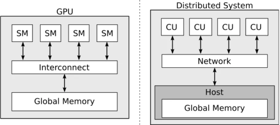
2.1.4 Mapping CUDA to Distributed Systems
The thread and memory hierarchy can be easily mapped onto a distributed system. Figure 2.1.4 compares the system diagram of a GPU to a distributed system to show the
GPU SM SM SMSM SMSM SMSM Global Memory Interconnect Distributed System Global Memory Network Host SM CU CUSM CUSM CUSM
Figure 2.1.4: Comparison of a GPU (left) and a distributed system (right).
initiates a kernel execution. Eachcompute unit(CU) can represent a machine or a processor. The network can be the interconnection on a motherboard or an Ethernet network.
In Phalanx, each CU performs the work of a SM in a smaller scale. A CU computes a block at a time. Messaging between the CUs and the host uses MPI. The support for different types of network depends on the installed MPI implementation. For instance, OpenMPI supports shared memory multiprocessors, Ethernet, InfiniBand, and Myrinet [7].
2.2 Compiling CUDA Kernels for Distributed Systems
To execute CUDA kernels in a distributed system, aPTX-to-LLVM compilertranslates CUDA kernels at the PTX level. PTX (parallel thread execution) is a virtual instruction set for CUDA. PTX is portable across current and future generations of GPU [12]. Compiling at the PTX level allows programmers to select any high-level programming languages that can be reduced to PTX. NVIDIA officially supports C/C++, FORTRAN,
and OpenCL. Chapter 3 discusses the PTX-to-LLVM compiler in detail. 2.3 Emulation of CUDA
The virtual architecture of CUDA cannot be directly mapped onto a distributed system. Also, not all PTX instructions can be mapped to CPU instructions. The Phalanx runtime
system emulates the scheduling of blocks onto CUs and the operation of some PTX instructions. Chapter 4 discusses the runtime system. Although the memory system is part of the runtime system, it is discussed separately in Chapter 5 due to its complexity. 2.4 Design for Heterogeneity
Phalanx has a portable design to ensure support for heterogeneity. Phalanx supports heterogeneity for different CPU architectures, operating systems and data-models. The PTX-to-LLVM compiler and the runtime system are written using Python and C++, respectively.
MPI provides messaging functionality in an abstract API. Different MPI
implementations support a different set of system configuration. For instance, OpenMPI support nodes of mix architectures. The case studies in Chapters 6 and 7 use a cluster of x86-32 and x86-64 machines.
Phalanx relies on LLVM (low-level virtual machine)1for heterogeneous code generation. First described by Lattner [14], LLVM is a compiler infrastructure that uses multi-stage optimization. LLVM accepts a low-level intermediate representation
(LLVM-IR) that uses a virtual instruction set instatic single assignment(SSA) form. Now, LLVM is an umbrella project consisting of many advanced optimization algorithms, language frontends and code generation backends. The code generation backends can transform LLVM-IR into the corresponding instruction set for a wide range of CPU architectures, including x86, ARM, MIPS, Sparc, and PowerPC. An experimental PTX backend has been added recently. In the future, Phalanx can use this new feature to implement CPU and GPU heterogeneity.
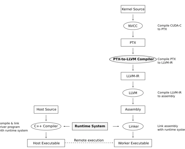
2.5 The Workflow of Phalanx
The following proposes a flow for CUDA-based programming for distributed
heterogeneous systems. Given a CUDA kernel source file written in CUDA-C, NVCC, from the NVIDIA CUDA Toolkit2, is used to compile the kernel source file to a PTX assembly file. The PTX-to-LLVM compiler, a component of the Phalanx framework, translates the PTX assembly file to LLVM-IR. LLVM generates assembly code for the target architecture from the LLVM-IR. At this point, the assembly code is usually
transferred to the target machine. To generate theworker executable, the assembly code is linked against the Phalanx runtime system, which is in the form of a shared library on the target machine. On the host machine, ahost executableremotely executes worker
executables. It is a simple C++ program that uses the Phalanx API for scheduling tasks onto the worker executables and does not perform the actual computation of the kernel. Figure 2.5.1 illustrates the proposed workflow for preparing a CUDA kernel for
Phalanx-based distributed computing.
Kernel Source PTX LLVM-IR Assembly NVCC PTX-to-LLVM Compiler LLVM Worker Executable Linker Compile CUDA-C to PTX Compile PTX to LLVM-IR Compile LLVM-IR to assembly Link assembly with runtime system
C++ Compiler Host Source
Runtime System
Host Executable Remote execution
Compile & link driver program with runtime system
Figure 2.5.1: The flow of CUDA-based programming for distributed heterogeneous system enabled by Phalanx.
Chapter 3
The PTX-to-LLVM Compiler
The PTX-to-LLVM compiler transforms PTX into LLVM-IR for heterogeneous code generation. The compiler restructures PTX instructions into code that suits the execution model of CPUs. The manycore architecture of a SM and the multicore architecture of a CPU is very different. The PTX execution model cannot be directly mapped to the execution model of the CPU. Section 3.1 discusses the characteristics of the PTX
execution model. Section 3.2 discusses a refined execution model to allow CPU execution of CUDA kernels. Section 3.3 discusses the handling of register and memory states. 3.1 Execution Model of PTX
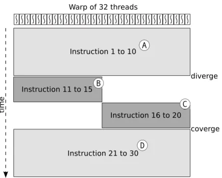
The PTX defines an execution model for running a massive number of parallel threads. At each issuing cycle, a warp of 32-threads is scheduled for execution. Figure 3.1.1
illustrates the logical execution of a warp. In the figure, a warp is executing a kernel of 30 instructions. Initially, all threads in the warp execute the first ten instructions in
basic-blockA. Each basic-block has only one execution path. Branching instructions can occur only at the last instruction of a basic-block. Logically, all threads execute in parallel. Instruction 10 is a branch that splits the warp into two halves. The first half-warp executes basic-blockB. The second half-warp executes basic-blockC. The diverged execution path forces serial execution of half-warps instead of parallel execution of all threads. Finally, a branch instruction at the end of basic-blockBandCreconverges the execution path to basic-blockD.
Instruction 1 to 10 Instruction 11 to 15 Instruction 16 to 20 Instruction 21 to 30 diverge coverge time Warp of 32 threads
Figure 3.1.1: Execution of a warp.
3.1.1 Branching and Warp Divergence
When threads in a warp are at different execution path due to branching, the warp is divergent. At each issuing cycle, the warp scheduler can execute only a subset of threads that have the same instruction pointer. Threads that have a different instruction pointer are disabled. The warp scheduler iterates over each execution path sequentially, using
multiple issuing cycles to complete the execution for a diverged warp. Since each path uses one issuing cycle, the worst case, in which all 32-threads have distinct instruction pointers, requires 32 issuing cycles for executing one warp. Therefore, warp divergence imposes a significant penalty for performance [12].
3.1.2 Thread Barrier
In PTX, barriers allow threads in a block to synchronize and cooperate. Threads reaching the barrier must wait until all threads in the block have reached the same barrier before resuming the execution. The barrier also guarantees all previous memory modifications are visible by all threads.
3.2 Refined Execution Model
Straitenet al.[10] discovered a simple transformation of CUDA kernels that allows efficient execution on CPUs. Their method converts CUDA kernels at source level by wrapping code segments between synchronization points–entry, exit and barriers–with a loop that iterates over every threads of the block. Deimoset al.[11] use a similar method, but the transformation is applied at PTX level and uses complex control-flow analysis for optimization.
.entry _Z21matrixMultipliyKernelPfS_S_i (
.param .u32 __cudaparm__Z21matrixMultipliyKernelPfS_S_i_A, .param .u32 __cudaparm__Z21matrixMultipliyKernelPfS_S_i_B, .param .u32 __cudaparm__Z21matrixMultipliyKernelPfS_S_i_C, .param .s32 __cudaparm__Z21matrixMultipliyKernelPfS_S_i_N) { .reg .u16 %rh<6>; .reg .u32 %r<33>; .reg .f32 %f<5>; .reg .pred %p<5>; $LBB1__Z21matrixMultipliyKernelPfS_S_i: mov.u16 %rh1, %ctaid.x; ... ld.param.s32 %r7, [__cudaparm__Z21matrixMultipliyKernelPfS_S_i_N]; set.le.u32.s32 %r8, %r7, %r6; ... @%p1 bra $Lt_0_2306; bra.uni $LBB10__Z21matrixMultipliyKernelPfS_S_i; $Lt_0_2306: mov.u32 %r14, 0; ... @%p2 bra $Lt_0_3842; mov.s32 %r15, %r7; ... ld.param.u32 %r20, [__cudaparm__Z21matrixMultipliyKernelPfS_S_i_B]; add.u32 %r21, %r20, %r17; ... ld.param.u32 %r24, [__cudaparm__Z21matrixMultipliyKernelPfS_S_i_A]; add.u32 %r25, %r22, %r24; ... $Lt_0_3330: ld.global.f32 %f2, [%r25+0]; ld.global.f32 %f3, [%r21+0]; mad.f32 %f1, %f2, %f3, %f1; ... @%p3 bra $Lt_0_3330; bra.uni $Lt_0_2818; $Lt_0_3842: mul.lo.s32 %r16, %r7, %r6; $Lt_0_2818: ld.param.u32 %r28, [__cudaparm__Z21matrixMultipliyKernelPfS_S_i_C]; add.s32 %r29, %r16, %r4; ... st.global.f32 [%r31+0], %f1; $LBB10__Z21matrixMultipliyKernelPfS_S_i: exit; $LDWend__Z21matrixMultipliyKernelPfS_S_i: }
Figure 3.2.1: Sample separation of PTX kernel entry into subkernels.
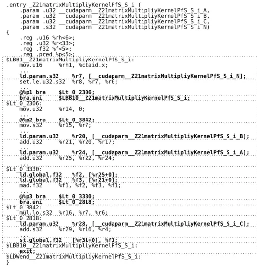
Comparing with the method of Deimoset al., Phalanx uses a relatively naive method. First, the compiler decomposes a kernel into basic-blocks by separating at each label.
Then, the compiler further decomposes these basic-blocks at every branch, memory, and control instructions. Control instructions include exit and barrier instructions. At this point, a kernel is partitioned into a sequence ofsubkernels. Subkernels are basic-blocks that can have only branch, memory, and control instructions as the last instruction. Figure 3.2.1 shows the PTX corresponding to the kernel defined in Listing 3.1. In the figure, the dotted lines denote the boundary of subkernels. The boldfaced lines highlight the
memory, branch, and other control instructions.
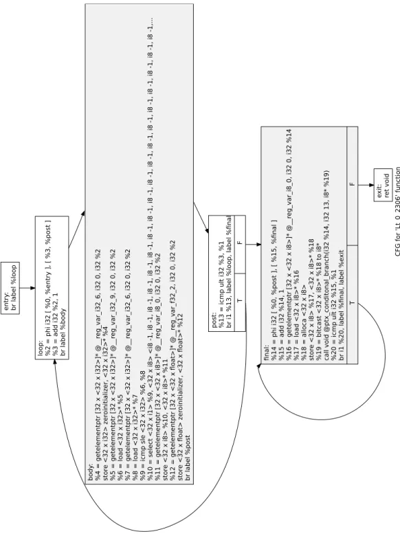
Unlike the method of Deimoset al., Phalanx does not join the partitioned subkernels. Instead, each subkernel is generated as an individual function in the LLVM-IR. Each PTX instruction in the subkernels is translated into a vector instruction that represents the execution of a warp. Thus, the vectors are 32-elements wide. Phalanx relies on LLVM to split or join vectors to match the supported vector size of the target architecture. Two loops are inserted for the vectorized subkernels. The first loop encloses all arithmetic instructions. Only the last instruction in a subkernel is non-arithmetic. The second loop encloses the last instruction. The loops iterate over a range of warps. The range is supplied as parameters to the subkernel function, indicating the start and the end of the range. Figure 3.2.2 is a control-flow graph of a sample subkernel function. In the figure, the first shaded box represents the body of the first loop. The second shaded box
represents the body of the second loop.
The resulting subkernel function does not account for warp divergence. Each vector instruction consists of the operations of 32 threads. PTX usessingle-instruction multiple threads (SIMT)execution. The SM automatically handles warp divergence. The CPU uses SIMD execution. The programmer must explicitly control divergence in vector operations. To handle warp divergence, the PTX-to-LLVM compiler generates two special functions for saving register contents and restoring the saved contents to the registers. The compiler does not generate code for scheduling subkernel functions or for
applying the register saving and restoring functions. The runtime system is responsible for these features. The discussion of the scheduler is in Chapter 4.
Listing 3.1: Sample matrix multiplication CUDA-C code.
1 _ _ g l o b a l _ _ 2 v o i d m a t r i x M u l t i p l i y K e r n e l (f l o a t A [ ] , f l o a t B [ ] , f l o a t C [ ] , i n t N) { 3 c o n s t i n t i = t h r e a d I d x . x + b l o c k I d x . x * blockDim . x ; 4 c o n s t i n t j = t h r e a d I d x . y + b l o c k I d x . y * blockDim . y ; 5 6 i f ( i >=N | | j >=N ) r e t u r n; 7 8 f l o a t r e s u l t = 0 ; 9 f o r( i n t k = 0 ; k<N ; ++k ) { 10 r e s u l t += A[ k+ j *N] * B[ i +k*N ] ; 11 } 12 C [ i + j *N] = r e s u l t ; 13 }
3.3 Handling Register and Memory States
The definitions of register and memory in PTX is different from those of CPU
architectures. The compiler must adjust for the difference to allocate register and memory accordingly.
3.3.1 Registers
The PTX does not define the upper limit of register use. Its instruction set uses a loose SSA form, in which register can be assigned multiple times as long as each assignment is located at a different basic-block. The Phalanx PTX-to-LLVM compiler must perform register allocation for each kernel to determine the minimum register count. The
algorithm for register allocation is simple. Since registers are typed in PTX, the following steps are repeated for each type. First, the compiler scans for registers that are used by multiple subkernels. These registers are added to thefinal setwithout further processing. Second, it searches for the live ranges of the remaining registers. A live range contains the first and the last occurrences of a register. Then, it continues with the algorithm in
C F G for ' L t_0_2 30 6' fun c ti on en tr y : br label % lo op lo op: % 2 = ph i i32 [ % 0 , % en tr y ], [ % 3 , % po s t ] % 3 = a dd i32 % 2 , 1 br label % body post: %13 = ic m p u lt i3 2 % 3, % 1 br i1 % 13 , la bel % lo op, label % fi n a l T F e xit: ret voi d body : % 4 = get el em en tpt r [ 32 x <32 x i3 2>] * @__r eg_va r_i 3 2_6 , i3 2 0, i32 % 2 st o re <3 2 x i32 > z e roinitializer , <32 x i3 2>* % 4 % 5 = get el em en tpt r [ 32 x <32 x i3 2>] * @__r eg_va r_i 3 2_9 , i3 2 0, i32 % 2 % 6 = lo a d <3 2 x i32 >* % 5 % 7 = get el em en tpt r [ 32 x <32 x i3 2>] * @__r eg_va r_i 3 2_6 , i3 2 0, i32 % 2 % 8 = lo a d <3 2 x i32 >* % 7 % 9 = ic mp sle <3 2 x i32 > % 6 , % 8 % 10 = selec t <32 x i1> % 9, <3 2 x i8> <i8 -1, i8 -1 , i8 -1, i8 -1, i8 -1 , i8 -1, i8 -1 , i8 -1 , i8 -1, i8 -1 , i8 -1 , i8 -1, i8 -1 , i8 -1, i8 -1, i8 -1 , i8 -1, i8 -1, .. . % 11 = getelemen tp tr [3 2 x <3 2 x i8>] * @__r eg_va r_i 8 _0, i32 0 , i3 2 % 2 st o re <3 2 x i8> % 10 , <32 x i8 >* % 1 1 % 12 = getelemen tp tr [3 2 x <3 2 x fl oat > ]* @__r eg_va r_f 3 2_2 , i3 2 0, i32 % 2 st o re <3 2 x fl oat > z er oinitializer , <32 x fl o a t>* % 12 br label % post fi n al: % 14 = ph i i3 2 [ % 0, % post ] , [ % 15 , % fi n al ] % 15 = add i3 2 % 14 , 1 % 16 = getelemen tp tr [3 2 x <3 2 x i8>] * @__r eg_va r_i 8 _0, i32 0 , i3 2 % 14 % 17 = load <32 x i8 >* % 1 6 % 18 = all oc a <32 x i8> st o re <3 2 x i8> % 17 , <32 x i8 >* % 1 8 % 19 = bi tc as t <32 x i8>* % 18 t o i 8 * c all vo id @pt x_c o n d itona l_br a n c h (i32 % 1 4, i32 1 3, i8* % 19 ) % 20 = ic m p u lt i3 2 % 15 , % 1 br i1 % 20 , la bel % fi n al, la bel % e xit T F
Listing 3.2 to fill thefinal set. Finally, thefinal setcontains the minimum set of registers. Listing 3.2: Pseudocode for register allocation.
1 f o r e a c h i n s t r u c t i o n { 2 f o r e a c h r e g i s t e r i n a c t i v e s e t { 3 i f r e g i s t e r l e a v e s i t s l i v e r a n g e { 4 remove r e g i s t e r f r o m a c t i v e s e t 5 add r e g i s t e r t o u n u s e d s e t 6 } 7 } 8 f o r e a c h o p e r a n d u s e d i n t h e c u r r e n t i n s t r u c t i o n { 9 i f u n u s e d s e t i s n o t empty { 10
remove a r e g i s t e r f r o m u n u s e d s e t and add i t t o a c t i v e s e t
11
} e l s e {
12
a l l o c a t e a new r e g i s t e r and add i t t o a c t i v e s e t
13 } 14 a s s i g n t h e r e g i s t e r f o r t h e o p e r a n d 15 } 16 } 17 f o r e a c h r e g i s t e r i n u n u s e d s e t { 18 add t o f i n a l s e t 19 }
Registers are statically allocated in the data segment of the worker executable. Each register is allocated as an array of 1024 elements, which is the maximum number of threads per block. Threads belonging to a warp have registers located consecutively in the array, allowing efficient SIMD load/store operations.
3.3.2 Memory
Shared memory is also statically allocated in the data segment. Since the worker
executable computes one CUDA block at a time, there is only one copy of shared memory. Unlike CUDA, the capacity of the shared memory is not fixed. A kernel can allocate as much shared memory as permitted by the amount of primary memory on the running machine.
3.4 Future Works
The PTX-to-LLVM compiler is still at an early stage, supporting only a subset of
instructions of CUDA compute capability 1.x. It also lacks support for local and constant memory. Aside from completing the support for the full PTX specification, future works should also add various optimization passes for better register allocation and performance. A control-flow analysis that predicts warp divergence and re-convergence would improve execution efficiency.
Chapter 4
The Runtime System
The Phalanx runtime system performs different functions in ahost processand in a
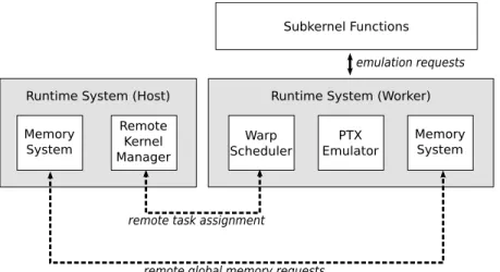
worker process. Figure 4.0.1 illustrates different components of the runtime system. A host process uses theremote kernel managerin the runtime system for scheduling remote kernel execution on a distributed system. By doing so, worker processes are spawned on each compute unit (CU) in the distributed system. CUs can be cores in a multicore CPU or remote machines connected to an Ethernet network. In a worker process, awarp schedulerin the runtime system schedules executions of subkernel functions. Subkernel functions depend on thePTX emulatorfor the implementations of memory, branch, exit and barrier instructions. Memory instructions are redirected to thememory system. Global memory requests are translated to MPI messages. Detail discussion of the
memory system is in Chapter 5. Other components of the runtime system are discussed in the following sections.
Subkernel Functions Warp Scheduler Memory System PTX Emulator Runtime System (Worker) Memory
System
Remote Kernel Manager Runtime System (Host)
emulation requests
remote global memory requests remote task assignment
4.1 Remote Kernel Manager
A host process executes kernel remotely on CUs in the distributed system. For comparison, Listing 4.1 and Listing 4.2 show sample codes of kernel invocations in Phalanx and in CUDA runtime API, respectively. Listing 4.3 shows the declaration of the corresponding kernel being invoked.
Listing 4.1: A kernel invocation example in Phalanx.
1 i n t main (i n t a r g c , c h a r ** a r g v ) { 2 / / i n i t i a l i z e p h a l a n x r u n t i m e s y s t e m 3 p h a l a n x : : c o m m u n i c a t o r . i n i t ( a r g c , a r g v ) ; 4 / / s e t a v a i l a b l e h o s t s i n t h e d i s t r i b u t e d s y s t e m 5 p h a l a n x : : c o m m u n i c a t o r . s e t _ h o s t s ( " 1 6 9 . 2 5 4 . 8 . 5 8 , 1 6 9 . 2 5 4 . 8 . 9 5 " ) ; 6 / / CUDA s p e c i f i c s : s e t u p b l o c k d i m e n s i o n 7 dim3 blockDim ( 3 , 4 , 5 ) ; 8 / / CUDA s p e c i f i c s : s e t u p g r i d d i m e n s i o n 9 dim3 g r i d D i m ( 6 , 7 ) ; 10 / / a l l o c a t e d a t a a r r a y s 11 i n t N = 1 0 2 4 ; 12 i n t * A = new i n t[N ] ; 13 i n t * B = new i n t[N ] ; 14 / / p o p u l a t e t h e d a t a a r r a y s 15 p o p u l a t e I n p u t ( A , B , N) ; 16 / / a l l o c a t e an a r r a y f o r p a s s i n g p a r a m e t e r s 17
v o i d * p a r a m e t e r [ ] = {&A , &B , &N} ;
18 / / l a u n c h k e r n e l on r e m o t e n o d e s 19 p h a l a n x : : l a u n c h K e r n e l ( 20 p a t h _ t o _ w o r k e r _ p r o c e s s , / / l o c a t i o n o f w o r k e r e x e c u t a b l e 21 g r i d D i m , / / g r i d d i m e n s i o n o f t h e k e r n e l 22 blockDim , / / b l o c k d i m e n s i o n o f t h e k e r n e l 23 p a r a m e t e r s , / / l i s t o f p a r a m e t e r s 24 s i z e o f ( p a r a m e t e r s ) /s i z e o f(v o i d* ) , / / number o f p a r a m e t e r s 25 n u m b e r _ o f _ p r o c e s s / / t o t a l number o f r e m o t e p r o c e s s e s 26 ) ; 27 / / c l e a n up 28 d e l e t e [ ] A ; 29 d e l e t e [ ] B ; 30 / / s h u t d o w n p h a l a n x r u n t i m e s y s t e m 31 p h a l a n x : : c o m m u n i c a t o r . f i n a l i z e ( ) ;
32
}
Listing 4.2: A kernel invocation example in CUDA runtime API.
1 i n t main (i n t a r g c , c h a r ** a r g v ) { 2 / / CUDA s p e c i f i c s : s e t u p b l o c k d i m e n s i o n 3 dim3 blockDim ( 3 , 4 , 5 ) ; 4 / / CUDA s p e c i f i c s : s e t u p g r i d d i m e n s i o n 5 dim3 g r i d D i m ( 6 , 7 ) ; 6 / / a l l o c a t e d a t a a r r a y s 7 i n t N= 1 0 2 4 ; 8 i n t * A = new i n t[N ] ; 9 i n t * B = new i n t[N ] ; 10 / / p o p u l a t e t h e d a t a a r r a y s 11 p o p u l a t e I n p u t ( A , N) ; 12
/ / make s p a c e i n GPU g l o b a l memory
13 i n t * dA ; 14 i n t * dB ; 15 c u d a M a l l o c (&dA , s i z e o f( i n t) *N) ; 16 c u d a M a l l o c (&dB , s i z e o f( i n t) *N) ; 17
/ / t r a n s f e r CPU d a t a t o GPU g l o b a l memory
18 cudaMemcpy ( dA , A , s i z e o f(i n t) *N, cudaMemcpyHostToDevice ) ; 19 / / i n v o k e k e r n e l f o r e x e c u t i o n i n GPU 20 c u d a K e r n e l F u n c t i o n <<< g r i d D i m , blockDim > > >(A , B , N) ; 21 / / t r a n s f e r GPU d a t a b a c k t o CPU 22 cudaMemcpy ( B , dB , s i z e o f(i n t) *N, cudaMemcpyDeviceToHost ) ; 23 / / c l e a n up GPU memory 24 c u d a F r e e ( dA ) ; 25 c u d a F r e e ( dB ) ; 26 / / c l e a n up CPU memory 27 d e l e t e [ ] A ; 28 d e l e t e [ ] B ; 29 }
Listing 4.3: An example of CUDA Kernel declaration.
1
_ _ g l o b a l _ _
2
v o i d c u d a K e r n e l F u n c t i o n (c o n s t i n t A [ ] , i n t B [ ] , i n t N) ;
In CUDA runtime API, programmers explicitly state the allocation of global memory on the GPU. The API provides a set of memory transfer functions to copy data between CPU and GPU. Lines 10-12 in Listing 4.2 show the code for allocating global memory in
the GPU and copying arrayAto the GPU. Line 13 launches the kernel in a similar fashion to a regular function call in C/C++, but with a special kernel configuration before the parameter list. Line 14 copies the output data arrayBback to the host. Lines 15-16 release the global memory allocated in the GPU.
In Phalanx, the global memory resides in the host process. Unlike CUDA runtime API, Phalanx does not require any additional transfer from CPU memory to global memory. Worker processes can access any memory in the host process through remote global memory requests. However, the current implementation does not protect against out-of-bound memory access for remote global memory requests. So, worker processes may access to any memory location, causing security concerns.
The Phalanx runtime system requires explicit initialization and termination. These procedures correspond to lines 2 and 9, respectively, in Listing 4.1. They are required to properly initialize and terminate the underlying MPI system. Line 3 provides a list of machines on which worker processes are spawned. Here, the machines are specified by IP addresses. A machine may contain multiple CUs. If no machine are provided, worker processes are spawned on the same machine on which the host process is running. MPI assigns worker processes to process slots. Specification of the number of available process slots differs among MPI implementations. For OpenMPI, ahostfileis supplied using the MPI launch script (mpirunormpiexec) to list the number of slots on each host. User should avoid over-commiting–assigning more than one process to a logical processor core. Over-committing may degrade performance. The best practice is to assign one process slot per logical processor core.
The call tolaunchKernelat lines 11-16 signals the Phalanx runtime to spawn worker processes on the given machines. The first parameter is a path string that tells MPI the location of the worker executable. This path must be the same across all remote
kernel, respectively. The fourth parameter supplies a list of pointers to serve as kernel parameters. The fifth parameter declares the number of kernel parameters. The last parameter specifies the total number of worker processes to spawn.
Kernel invocation in Phalanx is synchronous, unlike the asynchronous kernel
invocation in CUDA runtime API. The remote kernel manager takes over until the kernel finishes and all worker processes have terminated. This is necessary to handle incoming task requests from the worker processes. Section 4.4 further discusses the task requests from worker processes.
4.2 Warp Scheduler
A worker process begins execution by sending a task request to the host process. The task request asks the host process to assign a pending CUDA block for the worker process. Each block is computed by a worker process. When the block has been completed, the worker process sends another task request. This procedure repeats until all blocks in the grid have been completed.
Once the worker process have received a block, it starts to schedule warps for subkernel executions. The warp scheduler maintains a set of state variables for every thread in the block.
live A Boolean value that, if True, indicates the thread has not completed its execution. diverged A Boolean value that, if True, indicates that the thread is disabled and has a
differentsubkernel IDthan the non-diverged threads of the warp. subkernel ID The identifier of the nextsubkernelto execute.
restore context A pointer to a structure containing all saved register values of a
divergedthread. It has anullpointer if the thread is not diverged.
execute every thread in the warp without checking their divergence state. As a result, threads that have been disabled due to divergence will also execute in the subkernels. Their registers could be corrupted in the process. When diverged threads re-enable, their registers are restored by the content of theirrestore contexts.
Listing 4.4 shows the pseudocode of the scheduler algorithm. First, the scheduler executes all warps for the first subkernel. As long as there arelivethreads, the scheduler finds ranges of warps that have the same subkernel ID and execute the subkernel for these ranges of warps. After each subkernel execution, the scheduler commits any pending memory transactions and increments the subkernel ID for each executed thread.
Listing 4.4: Algorithm of the runtime scheduler.
1 e x e c u t e c u r r e n t s u b k e r n e l o f a l l w a r p s 2 commit memory t r a n s a c t i o n 3 i n c r e m e n t s u b k e r n e l i d f o r a l l w a r p s 4 w h i l e l i v e t h r e a d s c o u n t i s n o t 0 { 5 b e g i n : = 0 6 end : = 0 7 w h i l e b e g i n < warp c o u n t { 8 f i r s t W a r p : = warp w i t h i d == b e g i n 9 i f f i r s t W a r p i s n o t a l i v e { 10 b e g i n : = b e g i n + 1 11 } 12 c u r r e n t S u b k e r n e l : = s u b k e r n e l o f f i r s t W a r p 13 end : = b e g i n + 1 14
w h i l e end < warp c o u n t and c u r r e n t S u b k e r n e l == s u b k e r n e l o f l a s t W a r p { 15 end : = end + 1 16 } 17 e x e c u t e c u r r e n t s u b k e r n e l o f warp r a n g e [ f i r s t W a r p , l a s t W a r p ] 18 commit memory t r a n s a c t i o n 19 i n c r e m e n t s u b k e r n e l i d f o r warp r a n g e [ f i r s t W a r p , l a s t W a r p ] 20 } 21 }
4.3 PTX Emulator
Some PTX instructions have no direct translation into assembly of the target architecture. These PTX instructions are converted into function calls that reference handling routines in the runtime system.
4.3.1 Branch Instructions
Branch instructions are handled once per warp. Forconditional branch, the runtime checks the predicates of all threads in the warp. If the predicates are the same–all True or all False, the warp is not diverging and the branch is treated as auniform branch. If, however, the predicates are different for some threads, the warp diverges. The branching threads are disabled by marking thedivergedflag and creating arestore context.
PTX allows a branch instruction to be marked asuniform. Auniform branch
guarantees that all threads in the warp participate the branch. Therefore, it hints the runtime to create a convergence point. When executing auniform branchin a diverged warp, the runtime swaps the running threads and the diverged threads. This allows the diverged threads to reach the same subkernel so that the warp converges, improving the efficiency of warp execution. For non-diverged warps, simply changing the current
subkernel IDto the destinationsubkernel IDis sufficient. 4.3.2 Memory Instructions
Instead of servicing each global memory requests immediately, they are serviced after the subkernel execution. This allows the runtime system to coalesce the requests from multiple warps and optimizes them to reduce network usage. Detail discussion of the optimization is in Chapter 5.
Shared memory store requests must be handled by the runtime system because the subkernel execute every thread in the warp, including the disabled threads. Failing to discard store requests fromnon-liveordivergedthreads could corrupt shared memory
content.
4.3.3 Exit Instruction
Exit instructions are handled once per warp. The runtime system clears theliveflag of all running threads in the warp and restores diverged threads, if any.
4.3.4 Barrier Instruction
In PTX, a barrier instruction guarantees that all previous memory transactions have been completed and all threads reaches the same instruction. The runtime system disables all threads reaching that barrier and restores any diverged threads that have not reached the barrier. When all threads have reached the barrier, the runtime restores all threads for execution.
4.4 Remote Requests
Worker processes send three types of remote request.
Task request A worker process actively asks for new task from the host process whenever it is idle.
Parameter request A worker process asks for parameter values from the host process. Global memory request A worker process loads from or stores to global memory,
which resides in the host process.
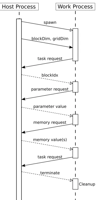
Figure 4.4.1 demonstrates a sample sequence of remote requests. The host process spawns a new worker process and sends the kernel configuration (block and grid dimensions). Then, the host process switches to passive mode, handling any incoming requests until all blocks of the grid have been completed. After receiving the kernel configuration, the worker process sends atask request. In reply, the host process assigns a block index (blockIdx) to the worker process, which begins to compute the kernel block indicated by the received block index. During the lifetime of the kernel block, the worker
process asks for parameter values usingparameter requestsand it asks for global memory usingglobal memory requests. Upon completion of the kernel block, the worker process sends anothertask request. If all blocks have been completed, the host process signals the worker process to terminate.
Since parameters in a CUDA kernel are copied-by-value, they are unchanged throughout the lifetime of a kernel grid. A worker process can safely cache a parameter value after the first request. This reduces the number of parameter requests and
consumption of network bandwidth.
Due to the complexity and importance of theglobal memory requests, they are discussed separately in Chapter 5.
Host Process
Work Process
task request blockIdx blockDim, gridDim parameter request parameter value memory request memory value(s) task request terminate spawn CleanupFigure 4.4.1: A sequence diagram illustrating the message-passing of remote requests be-tween a host process and a worker process.
Chapter 5
The Memory System
The memory system is part of the runtime system. It handles all memory requests from the subkernels. The performance of memory requests governs the maximum performance of a Phalanx application. Network bandwidth limits the maximum memory throughput for a Phalanx application. Comparing to the maximum throughput of PCI-express available to a GPU, a typical Ethernet network is significantly slower. With the limited network throughput, the memory system must optimize for maximum network utilization.
The rest of the chapter discusses the implementation of memory system. 5.1 Memory Operations
Listing 5.1 shows a simple parallel-prefix-sum kernel. This sample code shows all four types of memory operations. The right-hand-side (RHS) of line 5 is converted to a global memory load. The assignment of the same line translates to a shared memory store. At line 10, the assignment translates to a global memory store. The runtime system handles these three types of memory operations. The shared memory load at the RHS of line 8 is handled in the generated assembly using a simple load instruction of the target
architecture.
Listing 5.1: A simple parallel prefix sum kernel
1 _ _ g l o b a l _ _ 2 v o i d p r e f i x S u m K e r n e l (c o n s t i n t A [ ] , i n t B [ ] ) { 3 _ _ s h a r e d _ _ i n t smem [ 1 0 2 4 ] ; 4 i n t r e s u l t = 0 ; 5 / / s h a r e d memory p r e l o a d i n g 6 smem [ t h r e a d I d x . x ] = A[ t h r e a d I d x . x ] ; 7 / / b a r r i e r 8 _ _ s y n c t h r e a d s ( ) ; 9 f o r(i n t i = 0 ; i < t h r e a d I d x . x ; ++ i ) {
10 r e s u l t += smem [ i ] ; / / l o a d f r o m s h a r e d memory 11 } 12 / / s t o r e t o g l o b a l memmory 13 B [ t h r e a d I d x . x ] = r e s u l t ; 14 } 5.1.1 Global Memory
Global memory requests are not serviced immediately but after the execution of the subkernel. This allows all memory requests to be coalesced and optimized as described in Section 5.4.
Since a subkernel does not isolate disabled threads, which have exited or have diverged to another subkernel, disabled threads also generate memory requests. The runtime system is responsible to filter out these invalid requests.
A worker process forwards any global memory request to the host process through MPI messages. The request contains the data type of the requesting elements, the starting address of the elements and the number of elements to load or to store. For a load request, the host process loads the data at the starting address. The addresses of subsequent
elements are computed by incrementing the starting address by the byte length of the data type. The host process replies with a MPI message filled with the loaded data. For a store request, the host process continues to listen for the next message from the worker process. The next message contains the data to be stored. The host process directly stores the received data to the starting address.
5.1.2 Shared Memory
Shared memory requests are serviced immediately. Shared memory loads do not depend on the runtime system. They are converted directly into simple load instructions for the target architecture. The runtime system only handles shared memory stores. Similar to global memory requests, the runtime must filter out invalid shared memory store requests generated by disabled threads. Invalid shared memory loads are not removed. Since
diverged threads have kept a copy of the register values, these invalid loads cannot corrupt the registers of these threads.
5.2 Handling Heterogeneous Data Model
Phalanx supports heterogeneous data model in the distributed system. The CUDA and LLVM virtual architectures share the same data types. All integers are in 2’s complement representation. CUDA supports only 8, 16, 32 and 64-bit integers. LLVM supports any integer of bit length 1 to 223−1. For floating-point numbers, both use IEEE754
compliant types. For memory address, Phalanx forces all addresses to be 64-bit wide. On a 32-bit host machine, 64-bit addresses are simply truncated. Any architecture that
implements 2’s complement integer representations and IEEE754 single and double precision floating-point representations can be used in Phalanx.
Not all MPI implementations support data model heterogeneity. OpenMPI provides automatic conversion between big and little endians. However, heterogeneity support appears to be incomplete for some features. Theremote-memory access(RMA) defined in the new MPI standard [6] breaks in OpenMPI when working in a 32/64-bit heterogeneous cluster. Phalanx does not use the RMA feature. Phalanx uses only point-to-point
communication of MPI. RMA allows one-sided communication, removing the need to have a passive handler in the host process. The RMA feature can be useful in the future. 5.3 Memory Consistency
The massively parallel execution requires CUDA to adopt a weak memory consistency model [15]. This means modifications in memory are guaranteed to be visible only at barriers. It allows Phalanx to use aggressive optimizations for memory operations and thread scheduling.
5.4 Optimizing Global Memory Requests
Global memory throughput limits the performance of a Phalanx application. Section 5.4.1 discusses the performance impact of memory throughput for any system in general. Sections 5.4.2 and 5.4.3 explain the optimizations used by Phalanx for maximizing global memory throughput.
5.4.1 Principle of Balance
The performance of a system is limited by both computation and I/O throughput. The classical principle of balance states that the best performing system should balance the two throughputs. Given the number of processors isp, their peak compute throughputs areC
operations per second and they are connected through a network with bandwidthBbytes per second, the following equation [16, 17] characterizes the balance of such a system:
Ioptimal= p·C
B . (5.4.1)
Ioptimalis the peak arithmetic intensity of a computation. It has units ofoperations per byte. When a computation has an intensity that matchesIoptimal, the system computes as fast as I/O transfer. At this point, the system is the most efficient. Any computation that has an intensity higher thanIoptimal is compute bounded. If the intensity is lower than
Ioptimal, the computation is I/O bounded. A compute bounded computation is preferable because the system is not wasting processor time to wait for I/O.
For distributed systems, the network bandwidth is often significantly slower than the total compute throughput of all processors. This suggests that a suitable computation for distributed systems must have a high arithmetic intensity and the required intensity increases as the number of processors increases. As a result, most computations become I/O bounded.
5.4.2 Caching
Caching can raise the effective I/O bandwidthBe f f, thereby reducesIoptimal. Given a cache with bandwidthBcache, a network with bandwidthBnet and the percentage of I/O served from the cache isα, the effective bandwidthBe f f is characterized by the following equation:
Be f f = (1−α)Bnet+αBcache. (5.4.2)
WhenBcache>Bnet andα>0,Be f f is greater thanBnet.
Caching exploits data locality and temporarily stores fetched global memory in a worker process. The Phalanx runtime system implements a direct-mapped cache for each worker process. Based on the transfer pattern of the computation and available memory, the cache can be resized accordingly for each machine to optimizeα.
The cache is local to each worker process. It could be beneficial for future versions to allow a shared cache for all worker processes on the same machine. It could further reduce the network traffic.
Shared memory is not cached and it is not beneficial to do so. Shared memory is implemented as a static data segment in a worker process. Access to shared memory is direct, whereas access to cache goes through a hash table lookup. Therefore, the cache is slower than the shared memory.
5.4.3 Transaction Size
For any global memory transaction, a worker process sends a request message that
contains the data type, address and element count. Whenever the total size of transferring data is not much greater than the size of the request message, memory transaction
becomes very expensive. The request message has a constant size of 20-bytes (or 160-bits), without including additional overheads from the MPI implementation or from the network protocol.
When the transaction size is very large comparing to the overheads, network
utilization improves. For loading global memory, Phalanx uses a minimum fetch size. By default, each load transaction always fetches at least 4-kB of consecutive data. This over-fetching is beneficial most of the time. The coalesced memory access pattern, which is recommended for CUDA programming [13], guarantees that CUDA kernel loads batches of consecutive data. Moreover, the spatial locality of algorithms increases the chance of consumption of nearby data for each load. Since the cache stores all fetched data, any subsequent load transaction can be reduced into a fast cache load if it refers to cached data.
The runtime system sorts all load requests according to their addresses. It searches for the longest consecutive list of the sorted requests and services them in one transaction. If the transaction size is too small, it will append dummy requests to the list. It repeats until all requests are serviced.
For storing global memory, Phalanx does not mandate a fix transaction size. It only tries to coalesce memory requests to use fewer MPI messages. The runtime system sorts all memory requests according to their addresses. It searches for the longest consecutive list of the sorted requests and services them in one transaction. It repeats until all requests are serviced.
Chapter 6
Case Study: Matrix Multiplication
To demonstrate the feasibility of the Phalanx framework, this chapter and the following chapter present two case studies. In each case study, an application is written for serial and parallel execution. The parallel execution version uses Phalanx. Benchmarks are done to measure the performance gain by parallel execution.
A Core 2 Duo machine and two Core-i7 machines are used in the benchmarks. One of the Core-i7 machines are running in 64-bit mode. Other machines are running in 32-bit mode. All machines are running Ubuntu 10.04 OS.
For the parallel execution benchmark, all three machines are connected to a Gigabit Ethernet switch to form a small distributed system. The setup has a heterogeneous data model that mixes 32-bit and 64-bit processors. The Phalanx host process runs on the Core 2 Duo machine and it schedules worker processes onto the two Core-i7 machines. Each Core-i7 machine has four HyperThread execution cores. Together, the two Core-i7 machines provide 16 logical cores to serve as compute units in the Phalanx setup. The parallel executions are configured to use all 16 compute units with one worker process per unit. The MPI implementation used is OpenMPI 1.4 with TCP/IP based messaging. The serial execution benchmarks are performed on the 32-bit Core 2 Duo machine and the 32-bit Core-i7 machine.
6.1 Application Background
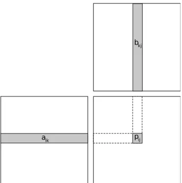
A matrix multiplication application is written using Phalanx. For simplicity, only square matrices are considered. The productPof the multiplication between twoN×N
![Figure 2.1.2: CUDA memory hierarchy and its relation with the thread hierarchy [12].](https://thumb-us.123doks.com/thumbv2/123dok_us/10111857.2911751/21.918.198.780.136.595/figure-cuda-memory-hierarchy-relation-thread-hierarchy.webp)
![Figure 2.1.3: Logical structure of NVIDIA streaming multiprocessors of compute capabil- capabil-ity 1.x [13].](https://thumb-us.123doks.com/thumbv2/123dok_us/10111857.2911751/22.918.377.595.134.319/figure-logical-structure-nvidia-streaming-multiprocessors-compute-capabil.webp)