High Capacity Colored Two Dimensional Codes
Antonio Grillo∗, Alessandro Lentini∗, Marco Querini ∗ and Giuseppe F. Italiano∗ ∗Department of Computer Science, Systems and Production
University of ”Tor Vergata” Via del Politecnico 1, 00133 Rome Italy Email: grillo;lentini;[email protected]
Abstract—Barcodes enable automated work processes without human intervention, and are widely deployed because they are fast and accurate, eliminate many errors and often save time and money. In order to increase the data capacity of barcodes, two dimensional (2D) code were developed; the main challenges of 2D codes lie in their need to store more information and more character types without compromising their practical efficiency. This paper proposes the High Capacity Colored Two Dimensional (HCC2D) code, a new 2D code which aims at increasing the space available for data, while preserving the strong reliability and robustness properties of QR. The use of colored modules in HCC2D poses some new and non-trivial computer vision challenges. We developed a prototype of HCC2D, which realizes the entire Print&Scan process. The performance of HCC2D was evaluated considering different operating scenarios and data densities. HCC2D was compared to other barcodes, such as QR and Microsoft’s HCCB; the experiment results showed that HCC2D codes obtain data densities close to HCCB and strong robustness similar to QR.
I. INTRODUCTION
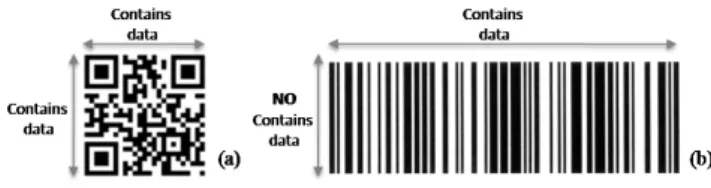
Barcodes have become widely popular because of their reading speed, accuracy, and functional characteristics. As barcodes became popular and their convenience universally recognized, the market began to call for codes capable of storing more information, more character types, and that could be printed in smaller space. As a result, various efforts were made to increase the amount of information stored in barcodes, such as increasing the number of barcode digits or laying out multiple barcodes. However, these improvements have some negative effects, such as enlarged barcode areas, complicated reading operations, and increased printing costs. Barcodes may be referred to as linear or one-dimensional (1D) codes. However, barcodes are available also in patterns of square, dots, hexagons and other geometric patterns within the image; such a kind of barcodes are referred to as matrix or bidimensional (2D) codes. Although 2D systems use symbols other than bars, they are generally referred to as barcodes as well. In order to increase the available data space, 2D codes introduce the capability of storing information in two directions. 2D codes contains information in both the vertical and horizontal dimensions, whereas 1D codes contains data in one dimension only. Figure 1 shows examples of 2D (a) e 1D (b) codes.
Available 2D codes solutions span from repeating a single 1D code over multiple rows to exploiting bidimensional shapes to represents data. Figure 2 illustrates the evolution of barcode technology. In particular, Figure 2 (a) shows the multiple
Fig. 1. Dimension for storing data in 2D (a) e 1D (b) codes
Fig. 2. Evolution of barcodes: multiple barcode layout(a), stacked barcode layout (b) and matrix barcode layout (c)
barcode layout: the main disadvantage related to this simple 2D layout is the need of multiple scans in order to get all the information contained in the barcode. Figure 2 (b) illustrates the stacked barcode layout: in this case one single scan is enough to obtain the stored information but the scanning equipment must be carefully aligned with the code orientation. Finally, in Figure 2 (c), the matrix barcode layout is presented: this layout enables to acquire information with one single scan and does not require the accurate alignment of the scanning equipment.
There are more than 20 types of conventional 2D codes. Figure 3 illustrates some examples of 2D codes; the main difference among the presented codes is in terms of the amount of data which can be stored in a single code. For example, Quick Response (QR)1code is able to store more than 7,000 decimal digits, while Maxi Code is able to store only 138 decimal digits. QR Code is a type of 2D codes developed by Denso Wave, a division of Denso Corporation at the time, and released in 1994 with the primary aim of being easily interpreted by scanner equipment.
The capability of storing more data in the same space taken by a classical two dimensional code represents one of the main challenges of the next generation barcodes. In order to increase 1QR Code is registered trademarks of Denso Wave Incorporated in Japan
and other countries.
Fig. 3. Characteristics of some types of 2D codes
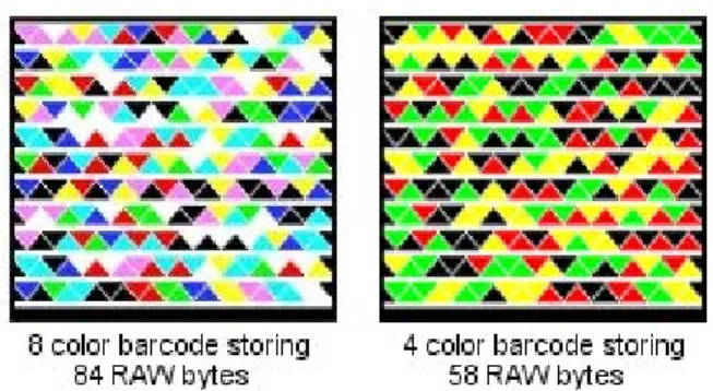
Fig. 4. An example of the Microsoft High Capacity Color Barcode (HCCB) (Viewed better in color)
data capacity, some 2D barcodes use colors to create more symbols, resulting in larger data capacity within the same size. Examples of such barcodes are the Color Bar Code System of Imageid Ltd [1] and the more widely diffused Microsoft’s High Capacity Color Barcode (HCCB) [2], [3], [4]. While HCCB may be used for a variety of applications, its most immediate application is for marking univoquely commercial medias such as motion pictures, video games, broadcasts, digital video recordings, etc... We now describe briefly the main features of HCCB (see Figure 4). It consists of rows of strings of symbols (triangles) of four different colors: black, red, green and yellow, and consecutive rows are separated by a white line. While the number of rows in a HCCB code may vary, the number of modules in each row is always a multiple of the number of rows. A module represents the basic entity for storing information in a 2D code. HCCB has a black boundary around it, further surrounded by a thick white band. These patterns are designed to act as visual landmarks in order to locate the barcode in an image. The black boundary at the bottom of HCCB is thicker than the boundaries on the other three sides: the bottom boundary acts as an orientation landmark, as barcodes may be at an arbitrary orientation in the image. The last 8 symbols on the last row are always in the fixed order of black, red, green and yellow (2 symbols per color) and can be used as a color palette during the scan. The
main limitation of the HCCB code is related to the fragility of the detection and alignment mechanisms. Indeed, the detection process works as follows: it starts from a point which is supposed to be at the interior of the code and proceeds on squares of larger sizes until it recognizes the white border around the code; after the white border has been located, it starts the alignment process by looking for the thick bottom boundary. The fragility of the detection process derives from the fact that not all the images inside a white border are necessarily codes (thus giving rise to delayed failures, which will be explained later), while the weakness of the alignment process derives from the facts that different slopes in the scan phase might result in failures to properly recognize the thick bottom boundary [5].
The increased data density obtained with the usage of colors comes at an additional cost. Today a Print&Scan process is commonly used for image reproduction and distribution. Indeed, often images are converted between printed and digital formats. A rescanned image may look similar to the original, but it may have been distorted during the process. Indeed, reading 2D color codes poses significant computer vision challenges [5], [6], [7]. This is due to several factors, and we cite only few of them in the following. First, the color balance may be drastically different in different code readers. Second, the images containing codes may be taken by unexperienced users, and thus the location of the barcode in the image, its orientation, its slope, etc. can be mostly unconstrained. Furthermore, possible transformations in the prospective can distort the geometry of the barcode. Last but not least, the light conditions under which the images are taken can vary dramatically.
Not all the scenarios where black and white 2D codes are currently exploited may benefit from the introduction of colors; in many scenarios 2D codes have to be copied or transmitted through fax, and fast color printers and color fax machines are not yet widely diffused in today’s offices. On the other hand, the availability of new low cost hardware may solve some of the problems that arise in the Print&Scan process. Since in many cases the Print operation is executed once while the Scan operation is likely to be repeated many times, we can consider that replacing ad-hoc hardware for scanning 2D codes by inexpensive mobile phones equipped with a megapixel camera may dramatically boost the adoption of colored 2D codes.
The contribution of this work is a new 2D code technology, named HCC2D (High Capacity Colored Two Dimensional), which use colors to increase the code data density. The intro-duction and recognition of colored modules in HCC2D poses some new and non-trivial computer vision challenges, such as handling the color distortions introduce by the hardware equipment that realizes the Print&Scan process. The HCC2D codes presented in this paper are able to support different types and sizes of data input, and adapt smoothly the code dimension to the actual input size. In order to support all those scenarios in which the Print&Scan process imposes the usage of only two colors (i.e., Black&White) HCC2D
considers Black&White codes as codes with exactly two colors. In particular, HCC2D has been designed so as to be fully compatible with the standard QR code, which is currently the most widespread 2D code technology (a standard QR code represents the simplest case of our 2D colored code). The main advantage of HCC2D over QR is that HCC2D is able to store substantially more data than QR, while preserving the strong reliability and robustness properties of QR.
We developed a prototype of HCC2D, which realizes the entire Print&Scan process, tested this prototype in many experiments considering different operating scenarios and data densities, and compared it to QR and HCCB. In our experi-ments, HCC2D codes obtained data densities close to HCCB and strong robustness similar to QR. In particular, HCC2D resulted to be very robust, and capable of resisting to dirt, damage and distortion, and introduced little computational overheads compared to QR.
II. STANDARDQR CODE
Standard QR codes as well as other black and white 2D codes store data using a graphical representation; the core of this representation is based on the arrangement of multiple simple geometric shapes over a fixed space. A generic 2D code is required to perform efficiently at least the following three functions:
• the position detection function is critical; elements that serve as position detection function give to the acquisition process the capability of identifying the presence of a 2D Code in the acquired image;
• the alignment function is required to synchronize the Scan process on the right position of a 2D code. This function exploits some alignment patterns placed by the Print process in a well known position. Hence, the Scan process focuses on retrieving these well known patterns in order to position correctly the 2D code.
• the data function is required to encode the input data in a specific graphical representation. Some additional goals may be reached by the data function; error correction and data masking are examples of these functions for strengthening the 2D code.
In particular standard QR codes adopt an arrangement of black and white squares of different sizes for all the required functions. In the following, some of the features provided by QR codes will be discussed.
A. High Capacity Encoding of Data
While conventional 1D codes store up to 20 decimal digits, QR Code is able to store from several dozen to several hundred times more information. QR Code can handle a large variety of data, such as binary, numeric and alphabetic characters, Kanji, Kana and Hiragana (Japanese) symbols, and control codes. If the input is represented by decimal digits, one code can encode up to 7,089 decimal digits (see Figure 3).
B. Small Printout Size
Since QR code carries information both horizontally and vertically, it is capable of encoding the same amount of data in approximately one-tenth the space of a traditional 1D code.
C. Dirt, Damage and Distortion Resistant
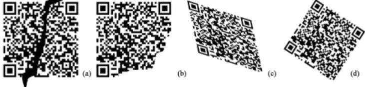
QR code has error correction capability. Data can be re-stored even if the symbol is partially dirty and damaged (see Figure 5). A maximum of 30% of the codewords can be restored. A codeword is a unit that constructs the data area. In the case of QR code, one codeword is equal to 8 bits. Thanks to its alignment function, QR Code is resistant to distorted acquisitions.
Fig. 5. Samples of QR Code dirty (a), damaged (b), distorted (c), and rotated(d).
D. Readable from any direction in 360 degrees
QR code is capable of 360 degrees (omni-directional) reading. This task is accomplished through position detection patterns located at the three corners of the symbol. These po-sition detection patterns guarantee stable high-speed reading, circumventing the negative effects of background interference. E. Structured Append Feature
If a single QR code is too large for the print space available, a splitting function may be applied to obtain smaller QR codes containing the same data. One data symbol can be divided into up to 16 codes, which can be printed in smaller areas (see Figure 6).
Fig. 6. Single QR Code splitted in four smaller QR Code
F. Standardization Process
QR codes have become widely used for two reasons: QR code specifications are clearly defined and made public and the QR codes can be freely usable. QR code is open in the sense that the specification of QR code is disclosed and that the patent right owned by Denso Wave is not exercised.
III. HIGHCAPACITYCOLOREDQR CODE
The main goals of our HCC2D code are to increase the space available for data and to preserve strong robustness and error correction properties similar to the original QR standard. HCC2D increases the storage space by generating each module
of the data area with a color selected from a color palette. Figure 7 illustrates samples of HCC2D with 4 colors HCC2D (Figure 7 (a)) and 16 colors (Figure 7 (b)).
Fig. 7. Samples of the High Capacity Colored Two Dimensional Code (HCC2D) version 5 and error correction level H: 4 colors (a) and 16 colors (b) (Viewed better in color).
In the standard QR code each module represents a single bit following a simple rule: black squares store 1 and white squares store 0. To ensure robustness, we have designed similar mechanisms to those available in the standard QR code; in particular, we have applied the Reed Solomon error correction codes for correcting code modules that represent more than one single bit. This way, HCC2D defines a superset of the standard QR code set, and thus it is able to maintain fully compatibility with QR.
Fig. 8. Structure of a generic QR Code
A standard QR Code can be represented as shown in Figure 8; the structure is composed of some elements that perform the various functions. The available space in each symbol may serve asFunction Patternsor asEncoding Region. The Position Detection Patterns, the Alignment Patterns, the Timing Patterns, and the Separators for Position Detection Patterns support the Scan process in detecting the presence, the right orientation and the correct slope of a QR code into an image. The Format Information describes the error correction level used in the code; it is possible to use four different error correction levels in the HCC2D code: the lower level (i.e., Level L) is able to correct about 7% of the data, the Level M restores about 15% of the data, the Level Q
is able to fix about 25% of the data, and the higher level (i.e., Level H) corrects approximately 30% of the data. The Version Information contains the real size of the code; it is possible to generate QR codes starting from Version 1 (i.e., 21x21 modules) to Version 40 (i.e., 177x177 modules). Finally theData and Error Correction Codewordscontains input and error correction data.
We designed the HCC2D code preserving all theFunction Patterns, theFormat Information and theVersion Information defined in the standard QR code. Saving the structure and position of such critical information allows HCC2D code to preserve compatibility with the standard QR code. Further-more, the space required by all this information is small, so we did not reduce this space to increase the data density. Any modification to such information may led to failures in the recognition process. The most important changes are gathered in the Data and Error Correction Codewords area. The most noticeable difference with a standard QR code is that the modules may be of different colors; in a code with a palette composed by at least 4 colors each module is able to store more than one bit. Introducing colors in the data and error correction area requires to address some issues, which will be analyzed next.
A. HCC2D Code Tables
The HCC2D Code Tables contain some information such as the total codewords count, the symbol version, the error correction level, the Reed-Solomon block type, etc. The aim of these tables is to support users in selecting the best code once the size and kind of the input data and the desired error correction level are known. In order to define the table it is possible to refer to those published in the ISO/IEC 18004 document that contains the definition of the standard QR code. The Bits per Module (BpM) can be defined as the number of bits that a single module is able to store:
BpM = log2(number of colors)
The more colors available, the more data can be stored into the code. In Figure 9 the data capacity for the smaller versions of QR Code are detailed.
Fig. 9. Data capacity for smaller version of standard QR Code
When considering values for BpM greater than one, values contained in the Data Capacity column vary. In particular, since each module is able to store exactly BpM bits each value
has to be multiplied by the BpM value as shown in Figure 10. The Remainder Bits are bits used to fill empty positions of the symbol encoding region after the final symbol character in the standard QR codes. They follow the same simple rules: the new value of Remainder Bits is obtained by multiplying the old value by the BpM value.
Fig. 10. New values for data capacity for smaller version of HCC2D codes
Figure 11 illustrates the effective data capacity for version 1 and version 2 of QR and HCC2D when considering the use of a specific error correction level. The new effective capacity is obtained by multiplying the old values by the BpM value. Starting from these values and choosing the data type that will be encoded in the HCC2D code we can compute the real code capacity.
Fig. 11. Error Correction Level for version 1 and version 2 of standard QR codes and HCC2D codes
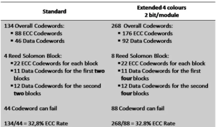
Figure 12 illustrates the situation for version 5 of HCC2D with the highest error correction level (i.e., level H). The Character Count Indicatorvalue gives the number of elements of a specific data type that are encoded in the code. Conversely, theMode Parameterexpresses the specific data type contained in the code. Since the main goal of HCC2D is to increase the number of elements that can be encoded in a single symbol, it is important to verify if this value fits in the space reserved by the standard.
Note that QR code version from 1 (i.e., 21x21 modules) to 9 (i.e., 53x53 modules) in alphanumeric mode reserves 9 bits for the Character Count Indicator, thus allowing for at most 511 (i.e.,29
−1) characters. However, with the increase of data density, HCC2D codes may contain more than 511
Fig. 12. Comparison between standard QR code and HCC2D code consid-ering version 5 and error correction level H
Fig. 13. Number of bits reserved for theCharacter Count Indicatorfor the various standard QR Code version
elements, and thus 9 bits are no longer sufficient. Hence, the space reserved for theCharacter Count Indicatorin a HCC2D code is defined according the following rules:
• 16 bit are reserved in the 8-bit Byte mode, regardless of the HCC2D Code version;
• for the remaining modes, a simple rule that combine the old Character Count Indicator length, Lengthold, and
the bit per module, BpM value is applied:
– Lengthold+ (BpM/2)if the number of bits per module is even
– Lengthold+ ((BpM+ 1)/2) if the number of bits per module is odd
Those rules are valid if and only if the color palette is composed by at least four colors; otherwise, the space for theCharacter Count Indicatorcan be defined as in QR codes (see Figure 13).
B. The Color Palette
If the Encoding Region is composed of colored modules, the Scan process needs to know the complete color palette in order to decode the symbol. In the standard QR code during the Scan process only the brightness information is taken in account. A simple solution is to consider the color palette as an a priori shared knowledge between the Print and the Scan processes; in such a scenario handling the distortions introduced by the specific hardware (e.g., scanner, camera, ...) represents a critical issue. Hence, in the HCC2D code we have introduced an additional field (i.e., the color palette) to ensure that the Scan process is able to know how many and which colors are used in the scanned code. Encoding the color palette directly in the HCC2D code helps in reducing failures in the
acquisition process due to the color distortions related to the specific hardware.
In image processing, it is important to define some quick failure criteria that avoid unnecessary computations if the Scan process delays a successful recognition. Forcing the start of a new Scan process instead of trying to recognize low quality images can reduce the delayed failure. Sorting the colors that compose the color palette according to the brightness value may represent a simple criterion to overcome the delayed failure problem. The Scan process starts recognizing only the color palette, if colors in the palette are not sorted as expected the process terminate with a quick failure, otherwise the Scan process can continue.
Furthermore, if the color palette is replicated around the bidimensional code, the quick failure rate can be further reduced. Each color palette that does not respect the expected color sorting should be discarded. If a minimum number of color palettes is successfully recognized, the Scan process can build the color palette for decoding the code by computing the average of the valid color palettes. In HCC2D the repeated color palettes are placed on the right side of the code; this single line will be adjacent to the Encoding Region for preserving compatibility. Considering version 1 of HCC2D code we introduce an overhead of about 4,76 %, i.e., one line of 21 modules over 441 modules. The overhead is reduced to 0,56% for version 40, i.e., one line of 177 modules over 31329 modules.
Analyzing the color palette extra field in the HCC2D code, the Scan process is able to build a model for evaluating each module in theEncoding Region. In the standard QR code the problem of distinguishing between light and dark modules is addressed by handling only the brightness information; exploiting the Quiet Zone to calibrate the Scan process, an appropriate threshold is chosen. In HCC2D a more complex similarity function is needed for handling colored modules. Since colors in computer graphics are usually represented as vectors in multidimensional space (e.g., the Red Green Blue model, the Cyan Yellow Magenta Key model, the Hue Saturation Lightness model, etc.), we solve the identification problem by using Euclidean distances between such vectors. In particular, modules in the encoding region are considered as vectors according to the specific color model used by the scanning equipment; the color recognized is given by the color in the palette which minimizes the vector distance.
C. Data Masking
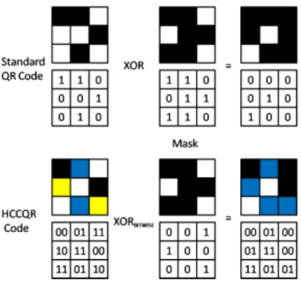
The main purpose of data masking in the standard QR code is to reach an appropriate balance between dark and light areas and to avoid that patterns similar to those used for Position Detection, Alignment and Timing appear in the Encoding Region. The HCC2D needs a similar function for preserving the Scan process in recognizing the Function Patterns and increasing the code robustness. The standard QR code defines eight different masks; each mask is generated according to a simple rule that mimics the Function Patterns. The Print process has to select the mask that obtains the best score
according to a scoring rule that is based on some bitwise XOR operations. Switching the brightness of some modules (i.e., light modules become dark modules and vice versa) is the result of data masking.
Fig. 14. Sample application of data masking in standard QR code and HCC2D code
Since HCC2D increases the number of bits per module (BpM), the standard scoring rules are no longer useful and we need to define new bitwise operations that are able to handle more than one bit per module. As far as the mask selection step is concerned, the HCC2D code is considered as a binary matrix composed simply of dark (i.e., the darkest colors) and light (i.e., the lightest colors) modules; the score for each mask is computed as in the standard QR code without taking in account the chromatic information of modules which is disjoint by the brightness information. Once the best mask is identified, each bit of the mask has to be used for switching the color of the module in the Encoding Region. For each module a bitwise operation between the bit in the mask and each bit that is stored in the module has to be performed. Figure14 shows an example of how the data masking process works for a 3x3 modules grid with 4 colors, considering both the standard QR code and the HCC2D code.
To preserve the balance between dark and light areas, we need to properly organize the palette. The colors are sorted in descending order according to the brightness information, the lighter colors first and the darker colors last; the color palette is then splitted in two halves and the second part is sorted in reverse order. As shown in Figure 15, this simple reorganization of colors in the palette results in increasing the minimum brightness distance between switched colors from 10% up to 35%.
IV. EXPERIMENTALRESULTS
We developed a prototype that implements the Print&Scan process for HCC2D codes. In particular, we implemented two different applications, the encoder and the decoder, for generating and acquiring HCC2D codes. The HCC2D code encoder was realized with the help of libqrencode [8], a C library for encoding data in standard QR code symbols, while the decoder was built with the help of zxing [9], an opensource Java project for improving the processing of 1D/2D barcodes. In our implementation, the decoder is
Fig. 15. Color palette organization for data masking
able to recognize standard QR codes as well; some of the operations executed in the acquisition process are preserved: recognizing the position detection pattern, recognizing and exploiting the alignment patterns, and reading the version and format information. After all these operations have been carried out, the decoder tries to detect the color palette. If the color palette is succesfully detected, the decoder tries to process a HCC2D code. Otherwise, it tries to decode a standard QR code. The image processing phase ends by returning a matrix representation of the scanned code; in the standard QR code a bitmatrix is sufficient to represent the modules whose brightness is greater (i.e., bit 0) or lower (i.e., bit 1) than the threshold value determined by analyzing the Quiet Zone. In HCC2D a bitmatrix is not adequate to represent the chromatic information of the modules. The acquisition process ends with a matrix of vectors that describe the scanned modules according to the color model used by the scanning equipment. In the HCC2D code design data are unmasked using the brightness information only; each scanned module is represented as a vector in the color model: a color distance rule is applied, the most similar (i.e., the closest) color in the palette is found and the associated bitstream is updated. Once the complete bitstream is reconstructed, the Reed-Solomon correction may be executed and the decoding process can retrieve the original input.
We now turn to the experimental results. We executed some performance tests using our prototype. We aimed at measuring the increase of the space available for data and the time computational overhead introduced by the use of colors, and thus we measured the time needed to convert all modules in a binary representation according to the color palette considered. Finally we reproduced the Print&Scan process for different code versions and different print qualities using widely diffused and low-cost print and scan equipment. The first issue we address is the increase of data density, and a general comparison is illustrated in Table I. Like most 2D codes, the QR Code data-density depends on several factors. The module size depends heavily on the printing and scanning resolutions. Microsoft offers its HCCB in black and
TABLE I
DENSITY OFBARCODESYMBOLOGIES AT600DPI. THE DATA FORHCCB IS TAKEN FROM[2]
Barcode Type Data Density [KB in square inch]
QR Code 0.627
HCCB 2.0
HCC2D 1.881
TABLE II
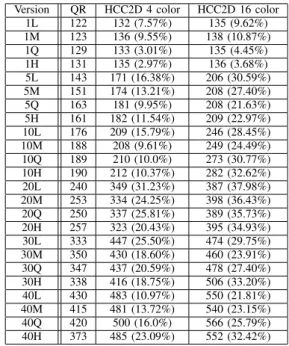
RESULTS OF THESCAN PROCESS TIME IN MSEC FORQRANDHCC2D Version QR HCC2D 4 color HCC2D 16 color
1L 122 132 (7.57%) 135 (9.62%) 1M 123 136 (9.55%) 138 (10.87%) 1Q 129 133 (3.01%) 135 (4.45%) 1H 131 135 (2.97%) 136 (3.68%) 5L 143 171 (16.38%) 206 (30.59%) 5M 151 174 (13.21%) 208 (27.40%) 5Q 163 181 (9.95%) 208 (21.63%) 5H 161 182 (11.54%) 209 (22.97%) 10L 176 209 (15.79%) 246 (28.45%) 10M 188 208 (9.61%) 249 (24.49%) 10Q 189 210 (10.0%) 273 (30.77%) 10H 190 212 (10.37%) 282 (32.62%) 20L 240 349 (31.23%) 387 (37.98%) 20M 253 334 (24.25%) 398 (36.43%) 20Q 250 337 (25.81%) 389 (35.73%) 20H 257 323 (20.43%) 395 (34.93%) 30L 333 447 (25.50%) 474 (29.75%) 30M 350 430 (18.60%) 460 (23.91%) 30Q 347 437 (20.59%) 478 (27.40%) 30H 338 416 (18.75%) 506 (33.20%) 40L 430 483 (10.97%) 550 (21.81%) 40M 415 481 (13.72%) 540 (23.15%) 40Q 420 500 (16.0%) 566 (25.79%) 40H 373 485 (23.09%) 552 (32.42%)
white, with four and eight different colors. Currently Microsoft laboratory tests have yielded using eight colors, 16,000 bits per square inch in its highest density form using a 600dpi business card scanner (cfr. [2]). Conversely, if a standard QR code symbol is printed with a resolution of 600 dpi, 4-dot printer, the module size is 0.17mm and will therefore require a scanner resolution of less than 0.17 mm (cfr. [10]). Using Version 19 of the standard QR code and the M correction level (i.e. about 15%) it is possibile to store 5,016 bits per square inch. Introducing a color palette composed of 8 colors, a HCC2D code of Version 19 and with the M correction level, is able to store 15,048 bits per square inch. HCC2D data density is slightly lower than Microsoft’s HCCB data density but while our solution preserves similar robustness in detection, alignment, and error correction of the standard QR code HCCB has no patterns that strongly support the detection and alignment process. Our solution increases the data density of standard QR code by a factor proportional to the BpM as mentioned in Section III-A and reaches a similar capacity to Microsoft HCCB.
Afterwards, we address the computational overhead for processing HCC2D codes by comparing the average time taken by the scan process. As far as standard QR codes are concerned, the time required for the automatic recognition of a code may be considered as a measure for the Scan
process. Selection of a proper binarization method is critical to the performance of barcode recognition system. Binarization of gray scale images is the first and important step to be carried out in pre-processing system. In binarizing an im-age, a simple and popular method is thresholding. Sahoo et al. [11] concluded that, among more than 20 thresholding methods, the Otsus method [12] which chooses the threshold that minimizes within-group variance, gives better results. A goal-directed performance evaluation of eleven popular locally adaptive thresholding algorithms were performed in [13] for map images. The experimental results indicated that Niblacks method with postprocessing step appears to be the best. Since our solution preserves the binarization for recognizing position detection and alignment patterns, the results mentioned in [11], [12], [13] are still valid.
In Table II we report results of an experiment focused on the recognition of more than 100 barcode images. To measure the overhead introduced by colors, times were taken after the alignment and detection phase. The experiment was run on a machine equipped with a Linux Slackware 13.0 operating system running on 1.73 GHz Intel dual core with 1 GB of RAM. The results report the average time in milliseconds for QR codes, HCC2D with 4 colors and HCC2D with 16 colors, and the overhead (in parenthesis, percentual values) introduced by HCC2D over QR. Our experiments show that, although the overhead introduced by HCC2D over QR tends to increase, as expected, with the number of colors and the code size, it seems to remain always within reasonable values (ranging from a minimum of about 3% for HCC2D version 1H with 4 colors to a maximum of about 38% for HCC2D version 20L with 16 colors). In particular, the average overhead introduced by HCC2D with 4 colors is about 15%, while the average overhead introduced by HCC2D with 16 colors is about 25%. The dependendence of the overhead on the error correction levels appears to be more complicated: in HCC2D with 4 colors the overhead (for the same code size) tends to decrease with the error correction levels for all versions except for version 40, while our experiments did not show a very strong correlation between the overhead of HCC2D with 16 colors and the error correction levels. In any case, the slowdown implied by the use of higher levels of error correction appears always limited (within about 5% of the total time).
Finally, in order to evaluate the usability of HCC2D code in a real setting, we realized a common Print&Scan scenario using a widespread inkjet multifunction equipment with print and scan capabilities. The equipment is able to print and to scan at different resolutions; in the test scenario we decide to fix the scan resolution while varying the print resolution. We have considered four different print resolutions: Draft Mode (i.e., 180 dpi), Text Mode (i.e., 360 dpi), Text and Photo Mode (i.e., 720 dpi), Text and Photo Mode (i.e., 720 dpi) and Photo (i.e., 1440 dpi). We experimented with a small print size (1 square inch) for different versions of the 4-colors HCC2D codes with the L error correction level; the Print&Scan process is repeated for the code versions: Version 5 (i.e., 37x37 modules), Version 10 (i.e., 57x57 modules)
TABLE III
USABILITY OF DIFFERENT VERSIONS OF THEHCC2DCODE VARYING THE PRINT RESOLUTION
Print resolution 180dpi 360dpi 720dpi 1440dpi
Version 5 No Yes Yes Yes
Version 10 No Yes Yes Yes
Version 15 No No Yes Yes
and Version 15 (i.e., 77x77 modules). Table III shows that only codes printed at poor quality levels (i.e., Draft Mode with a resolution of 180 dpi) fail to complete successfully the Print&Scan process. When the print resolution increases, the success rate depends on the HCC2D version: at 360 dpi only Version 15 (77x77 modules) failed on print sizes of 1 square inch.
V. CONCLUSIONS
In this paper we have proposed High Capacity Colored QR codes, a new 2D code which aims at increasing the space available for data, while preserving similar robustness, error correction and without loosing compatibility with the original QR standard. Our results show that HCC2D leads to larger data density compared to QR at the price of a small computational overhead. Though the data density is slightly lower than in HCCB, HCC2D does not suffer from the problems in detection and alignment of the 2D code.
REFERENCES
[1] E. Sali and D. M. Lax, “Color bar code system,” US Patent 7210631, February 2006.
[2] “High capacity color barcodes,” http://research.microsoft.com/en-us/projects/hccb/, Microsoft Research, May 2010.
[3] T. Bishop, “Software notebook: Color is key to Microsoft’s next-generation bar code,” http://www.seattlepi.com/business, April 2007. [4] I. Fried, “Microsoft gives bar codes a splash of color,”
http://news.cnet.com, April 2007.
[5] D. Parikh and G. Jancke, “Localization and segmentation of a 2d high capacity color barcode,” inProceedings of the 2008 IEEE Workshop on Applications of Computer Vision. IEEE Computer Society, January 2008, pp. 1–6.
[6] O. Bulan, V. Monga, and G. Sharma, “High capacity color barcodes using dot orientation and color separability,” inProceedings of Media Forensics and Security. SPIE, January 2009.
[7] K. O. Siong, D. Chai, and K. T. Tan, “The use of border in colour 2d barcode,” in2008 International Symposium on Parallel and Distributed Processing with Applications (ISPA’2008), December 2008, pp. 999– 1005.
[8] K. Fukuchi, “Libqrencode, aclibrary for encoding data in aqrcode symbol,” http://megaui.net/fukuchi/works/qrencode/, October 2010. [9] “Zxing, multi-format 1d/2d barcode image processing library,”
http://code.google.com/p/zxing/, Google Inc., May 2010.
[10] “Quick response code - printer head density and module size,” http://www.denso-wave.com/qrcode/qrgene3-e.html, Denso Wave, May 2010.
[11] P. K. Sahoo, S. Soltani, A. K. C. Wong, and Y. Chen, “A survey of thresholding techniques,” Computer Vision, Graphics, and Image Processing, vol. 41, pp. 233–260, February 1988.
[12] I. J. Kim, “Multi-window binarization of camera image for document recognition,” in Proceedings of the 9th International Workshop on Frontiers in Handwriting Recognition. IEEE Computer Society, October 2004, pp. 323–327.
[13] O. D. Trier and A. K. Jain, “Goal-directed evaluation of binarization methods,” in IEEE Transactions on Pattern Analysis and Machine Intelligence, vol. 17. IEEE Computer Society, December 1995, pp. 1191–1201.