PWS SPECIFICATIONS 1
Overview ... 2
High Level Features ... 6
Operating Parameters ... 7
Pinout and Terminal Descriptions ... 8
Physical Dimensions ... 9
Recommended Operating Conditions ... 10
Battery Charger Characteristics ... 10
Battery Charger with Load Sharing Mode ... 10
Power Consumption (WROOM-02 Module) ... 11
Onboard LEDs ... 11
Schematics ... 12
Power and Charger Circuit ... 12
Real Time Clock (RTC) Circuit ... 13
USB to Serial Circuit ... 13
ESP-WROOM-02 Circuit ... 14
GPIO and Connector Circuit ... 15
PWS SPECIFICATIONS 2
OVERVIEW
The Programmable Wireless Stamp (PWS) is a low cost micro-controller based wireless board tailored to general test and measurement, wireless data acquisition and IoT applications. The PWS is based off of the ESP-WROOM-02, a high performance wireless SOC by Espressif, especially designed for space and power constrained wireless data acquisition and IoT applications.
At the heart of the ESP-WROOM-02 SOC is the ESP8266EX chip. A 32-bit Arduino Compatible low power micro-controller with CPU clock of 80MHz, 50KB of user available RAM and an external 4MB of Flash memory.
Programmable Wireless Stamp Rev.A
The Programmable Wireless Stamp include a general purpose I/O connector for direct sensor connectivity as well as three PMOD connectors, one I2C, one SPI, and one UART/GPIO for plug and play I/O extension and utilization of the growing ecosystem of PMOD signal conditioning modules.
The PMOD is a standard created by Digilent and allows for precision data conversion, high-accuracy timekeeping, precision analog generation as well as advanced application specific functionality such as ambient-light sensing, capacity sensing and many others to have a common communication interface within a system.
The PWS augments that functionality by allowing, programmability and decision making in real time as well as wireless connectivity to the data produced by these peripheral modules.
PWS SPECIFICATIONS 3 Reference (http://digilentinc.com/Products/Catalog.cfm?NavPath=2,401&Cat=9)
The PMOD ecosystem is expanding rapidly. Companies like Maxim and Analog Devices have created several reference designs that are offered to the community via PMOD modules. Maxim, for example, offers a wide variety of analog, mixed-signal and sensor PMOD modules.
PWS SPECIFICATIONS 4 Maxim PMOD Modules (https://www.maximintegrated.com/en/design/design-technology/fpga-design-resources/pmod-compatible-plug-in-peripheral-modules.html)
Analog Devices offer a great variety of ADC and DAC PMOD modules. Analog Devices is the vendor that supplies National Instruments with the ADC and DAC chips that are part of National Instruments data acquisition devices.
Pmods™ by Analog Devices
The Stamp can be powered by an external Lithium Polymer battery for standalone operation. It also includes battery charger capability and constantly monitors its battery health status, generating user notifications messages when it is time for battery charging. Battery charging can be accomplished by simply plugging the PWS on a computer USB port.
A SD Card can be inserted in the Stamp’ SD Card connector for local data logging. The HW includes a Real Time Clock (RTC) for time stamped sensor data acquisition and data logging.
The Programmable Wireless Stamp firmware can be programmed in either C-language via utilization of the Arduino IDE or in National Instruments LabVIEW. A full set of LabVIEW API VIs is made available for easy access to the Stamp peripherals in LabVIEW. Two LabVIEW Templates are also provided to jump start your IoT and wireless data acquisition applications.
PWS SPECIFICATIONS 5
If LabVIEW is the language of choice for the programming of the Programmable Wireless Stamp firmware, the user will need to acquire the Arduino Compatible Compiler for LabVIEW by TSXperts-Aledyne. Through the utilization of the Arduino Compatible Compiler for LabVIEW, users can deploy LabVIEW code via USB cable to run embedded and standalone in the Stamp. This programming capability allows the user to create fully custom solutions from scratch or to extend and tailor the shipping examples and data logging applications to fit your specific project requirements.
The Programmable Wireless Stamp is ideally suited for the following applications:
Low-power remote data logging
Low-power remote monitoring and control
IoT (Internet of Things) application
PWS SPECIFICATIONS 6 Wireless data acquisition
HIGH LEVEL FEATURES
ESP-WROOM-02 WiFi Module : MCU 32-bit 80MHz Integrated TCP/IP protocol stack Flash Memory 4 MB with User RAM 50 KB (SRAM)
WiFI 802.11b/g/n at 2.4 GHz support WPA/WPA2 Integrated WEP, TKIP, AES, and WAPI engines +19.5dBm output power in 802.11b mode
FCC, CE, TELEC, Wi-Fi Alliance, and SRRC certified for WROOM-02 Module Supported Battery: Li-Po single cell, 3.7V, 500mAh minimum.
Micro SD Card Socket Real-Time Clock (RTC)
USB for Power/Programming (Speed up-to 921600) One I2C-Pmod™ Connector (Pmod™ Interface I2C) One SPI-Pmod™ Connector (Pmod™ Interface Type 2 SPI)
One UART/GPIO-- Pmod™ Connector (Pmod™ Interface Type 4 UART, Type 1 GPIO)
ESD Protection circuit for all GPIOs (Complies with IEC61000-4-2 level 4, MIL STD 883C-Method 3015-6: class 3)
Operating temperature range -20C to +55C
Input Voltage, Battery holder (Li-Po single cell): 3.4V-4.2 V (Typ. 3.7V) Input Voltage: Micro USB: 5V
Circuit Operating Voltage: 3.3V DC Current per I/O Pin: 12mA (max) Operating Current (Average) = 80 mA
PWS SPECIFICATIONS 7
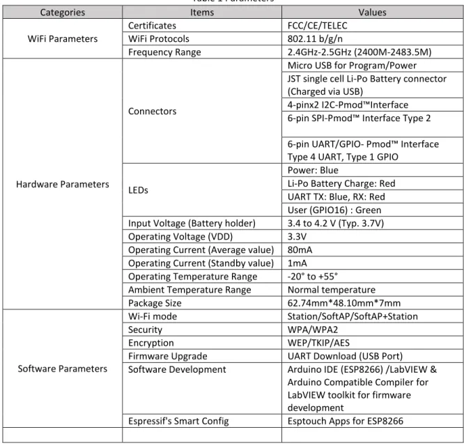
OPERATING PARAMETERS
Table 1 below describes the major parameters
Table 1 Parameters
Categories Items Values
WiFi Parameters Certificates FCC/CE/TELEC WiFi Protocols 802.11 b/g/n Frequency Range 2.4GHz-2.5GHz (2400M-2483.5M) Hardware Parameters Connectors
Micro USB for Program/Power JST single cell Li-Po Battery connector (Charged via USB)
4-pinx2 I2C-Pmod™Interface 6-pin SPI-Pmod™ Interface Type 2 6-pin UART/GPIO- Pmod™ Interface Type 4 UART, Type 1 GPIO
LEDs
Power: Blue
Li-Po Battery Charge: Red UART TX: Blue, RX: Red User (GPIO16) : Green Input Voltage (Battery holder) 3.4 to 4.2 V (Typ. 3.7V) Operating Voltage (VDD) 3.3V
Operating Current (Average value) 80mA Operating Current (Standby value) 1mA Operating Temperature Range -20° to +55°
Ambient Temperature Range Normal temperature
Package Size 62.74mm*48.10mm*7mm
Software Parameters
Wi-Fi mode Station/SoftAP/SoftAP+Station
Security WPA/WPA2
Encryption WEP/TKIP/AES
Firmware Upgrade UART Download (USB Port) Software Development Arduino IDE (ESP8266) /LabVIEW &
Arduino Compatible Compiler for LabVIEW toolkit for firmware development
PWS SPECIFICATIONS 8
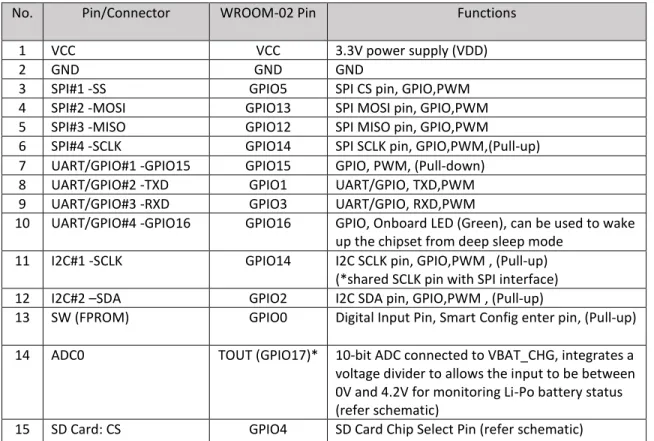
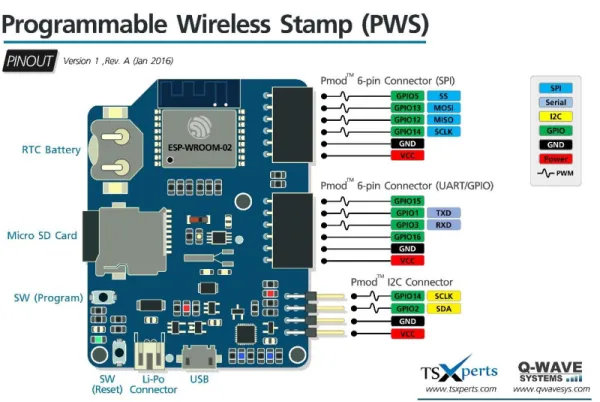
PINOUT AND TERMINAL DESCRIPTIONS
There are altogether 15 pin counts, the definitions of which are described in Table 2 below. Table 2 Pin Descriptions
No. Pin/Connector WROOM-02 Pin Functions
1 VCC VCC 3.3V power supply (VDD)
2 GND GND GND
3 SPI#1 -SS GPIO5 SPI CS pin, GPIO,PWM
4 SPI#2 -MOSI GPIO13 SPI MOSI pin, GPIO,PWM
5 SPI#3 -MISO GPIO12 SPI MISO pin, GPIO,PWM
6 SPI#4 -SCLK GPIO14 SPI SCLK pin, GPIO,PWM,(Pull-up) 7 UART/GPIO#1 -GPIO15 GPIO15 GPIO, PWM, (Pull-down)
8 UART/GPIO#2 -TXD GPIO1 UART/GPIO, TXD,PWM 9 UART/GPIO#3 -RXD GPIO3 UART/GPIO, RXD,PWM
10 UART/GPIO#4 -GPIO16 GPIO16 GPIO, Onboard LED (Green), can be used to wake up the chipset from deep sleep mode
11 I2C#1 -SCLK GPIO14 I2C SCLK pin, GPIO,PWM , (Pull-up) (*shared SCLK pin with SPI interface) 12 I2C#2 –SDA GPIO2 I2C SDA pin, GPIO,PWM , (Pull-up)
13 SW (FPROM) GPIO0 Digital Input Pin, Smart Config enter pin, (Pull-up) 14 ADC0 TOUT (GPIO17)* 10-bit ADC connected to VBAT_CHG, integrates a voltage divider to allows the input to be between 0V and 4.2V for monitoring Li-Po battery status (refer schematic)
15 SD Card: CS GPIO4 SD Card Chip Select Pin (refer schematic) GPIO0-GPIO15 can be INPUT, OUTPUT, INPUT_PULLUP, and INPUT_PULLDOWN.
GPIO16 can be INPUT, OUTPUT or INPUT_PULLDOWN. It is also XPD for deepSleep. Pin Interrupts may be attached to any GPIO pin, except GPIO16.
PWM may be used on pins 0 to 15. The value may be in range from 0 to 1023. Since the ADC is 10-bit resolution; 1023 is 100% duty cycle.
PWS SPECIFICATIONS 9 Figure PWS Pinout Graphical Diagram
PHYSICAL DIMENSIONS
Table 3 Dimension
Length Width Height
62.74mm 48.10mm 7mm
PWS SPECIFICATIONS 10
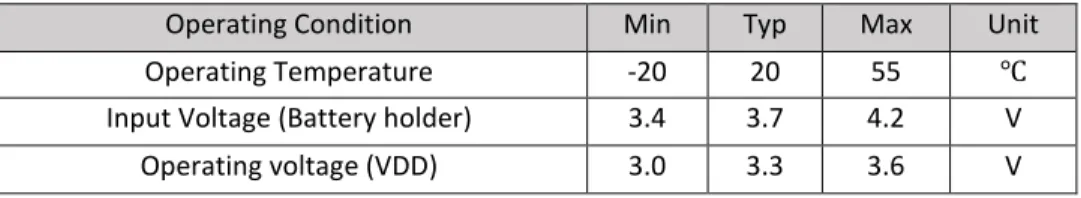
RECOMMENDED OPERATING CONDITIONS
Table Recommended Operating Conditions
Operating Condition Min Typ Max Unit
Operating Temperature -20 20 55 ℃
Input Voltage (Battery holder) 3.4 3.7 4.2 V
Operating voltage (VDD) 3.0 3.3 3.6 V
BATTERY CHARGER CHARACTERISTICS
DC Characteristics
Parameters Min Typ. Max Units
Charger Voltage (Constant-Voltage Mode)
4.168 4.2 4.232 V Charger Current
(Fast Charge Constant-Current Mode)
450 505 550 mA
Complete Charge Cycle (1000 mAh Li-Ion Battery)*
- - 240 minutes
* Li-Po batteries are charged at 4.2V with fast charge current at 500mA, the preferred fast
charge current for Lithium-Ion cells is at the 1C rate, with an absolute maximum current at the 2C rate. For example, a 500 mAh battery pack has a preferred fast charge current of 500 mA. This means that the MINIMUM capacity of the Li-Po battery shall be 500 mAh. Smaller cells will be damaged by this current and may overheat, develop internal gasses and explode; therefore generating a safety hazard. We strongly recommend that you select a Li-Po battery of at least 500mAh capacity (preferred 1000mAh). A bigger cell will take more time to charge, but won't be harmed or overheated.
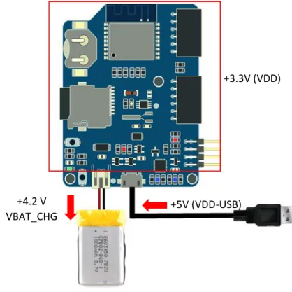
BATTERY CHARGER WITH LOAD SHARING MODE
The PWS includes a Li-Po charge circuit with load sharing mode that allows the PWS to charge the Li-Po battery while running on USB 5V power.
PWS SPECIFICATIONS 11 Figure Load Sharing (Power Supply+ Battery Charger)
POWER CONSUMPTION (WROOM-02 MODULE)
Table Power ConsumptionParameters Min Typical Max Unit
Tx802.11b, CCK 11Mbps, P OUT=+17dBm 170 mA
Tx 802.11g, OFDM 54Mbps, P OUT =+15dBm 140 mA
Tx 802.11n, MCS7, P OUT =+13dBm 120 mA
Rx 802.11b, 1024 bytes packet length , -80dBm 50 mA Rx 802.11g, 1024 bytes packet length, -70dBm 56 mA Rx 802.11n, 1024 bytes packet length, -65dBm 56 mA
Modem-Sleep 15 mA Light-Sleep 0.9 mA Deep-Sleep 10 uA
ONBOARD LEDS
+5V (VDD-USB)
+4.2 V
VBAT_CHG
+3.3V (VDD)
PWS SPECIFICATIONS 12
Onboard LEDs
SCHEMATICS
PWS SPECIFICATIONS 13
R
EAL
T
IME
C
LOCK
(RTC)
C
IRCUIT
PWS SPECIFICATIONS 14
ESP-WROOM-02
C
IRCUIT
PWS SPECIFICATIONS 15
GPIO
AND
C
ONNECTOR
C
IRCUIT
PWS SPECIFICATIONS 17
IMPORTANT INFORMATION
THE UTILIZATION OF THE PROGRAMMABLE WIRELESS STAMPS MATERIALS BIND THE USER TO THE FULL TERMS OF THE PROGRAMMABLE WIRELESS STAMP LICENSE AGREEMENT.
REFER TO THE PROGRAMMABLE WIRELESS STAMP LICENSE AGREEMENT DOCUMENT.
TSXperts LLC-QWAVE SYSTEMS MAKE NO EXPRESS OR IMPLIED WARRANTIES AS TO THE ACCURACY OF THE INFORMATION CONTAINED HEREIN AND SHALL NOT BE LIABLE FOR ANY ERRORS.