Systems Engineering Master Project
-100 101 106 105 104 103 102 107 system requirements design decisions parts connections lines of code number ofdetails caseorganizational and operation context user needs and system requirements
design and realization
case
System n sub-system system sub- com-ponent com-ponent com-ponent com-ponent System 1 sub-system system sub- com-ponent com-ponent com-ponent com-ponent organizational and operational context case connect SE body of Knowledge reflect depth breadth reflection Gerrit Muller HBV-NISE
Frogs vei 41 P.O. Box 235, NO-3603 Kongsberg Norway [email protected]
Abstract
The master study Systems Engineering is completed by performing a thesis project. This document describes objectives and guidelines for the project and the thesis.
Distribution
This article or presentation is written as part of the Gaudí project. The Gaudí project philosophy is to improve by obtaining frequent feedback. Frequent feedback is pursued by an open creation process. This document is published as intermediate or nearly mature version to get feedback. Further distribution is allowed as long as the document remains complete and unchanged.
All Gaudí documents are available at: http://www.gaudisite.nl/
1
Introduction
Students must do a research project as part of the Systems Engineering master education at Buskerud University College. The project is performed in the last semester of the study. The goals of the project, further elaborated in section 2, are to apply systems engineering techniques in practice and to do actual research.
The master project is 6 months full time work, resulting in 30 ECTS.
This document is mostly applicable for many master studies, although this document described the specific situation of Systems Engineering at BUC.
2
Project Goals and Positioning
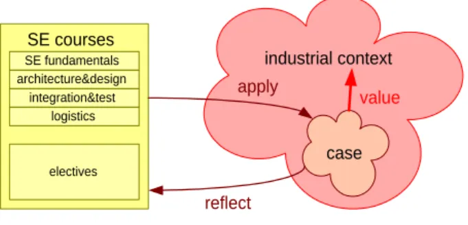
industrial context case SE courses SE fundamentals architecture&design integration&test logistics electives apply reflect value
Apply SE methods, techniques, and concepts in practice and reflect on its application, while providing value to the industrial sponsor
Figure 1: Objectives of Masters Thesis Project The main goals of the master project, shown in Figure 1, are:
• the students have to prove again their professional competence and the acquired
command of the systems engineering discipline by applying it to a selected problem;
• the selected problem has to be relevant in the context of the company in
which the student works, so that knowledge is truly put into practice.
• to facilitate the students to make the step from "just applying" to "critical reflection".
• to verify that students are capable to operate at academic level.
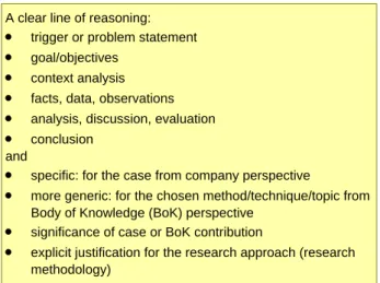
Figure reffig:SETPcriteria shows the assessment criteria for the master project: A good paper has a clear line of reasoning starting with a trigger or problem
A clear line of reasoning: · trigger or problem statement · goal/objectives
· context analysis · facts, data, observations · analysis, discussion, evaluation · conclusion
and
· specific: for the case from company perspective
· more generic: for the chosen method/technique/topic from Body of Knowledge (BoK) perspective
· significance of case or BoK contribution
· explicit justification for the research approach (research methodology)
Figure 2: Assessment criteria for the master project
statement, finally resulting in a clear conclusion. The paper has to provdie such line of reasoning specifically for the case from company perspective and more generic for the chosen method/technique/topic from Body of Knowledge (BoK) perspective. The scope of the case and the BoK contribution and their signif-icance play a significant role in grading. Finally, teh paper needs to provide a clear academic justification for the research approach (the research methodology), discussing aspects such as validity.
master project academic supervisor
coaching quality
grading company supervisor
coaching industrial case student research paper academic industrial industrial company sponsor industrial context usable results
Figure 3: Stakeholders of the Thesis Project
The project has multiple stakeholders with different concerns. Figure 3 shows at the right side the industrial stakeholders: the sponsor who provides the industrial context and who expects usable results, and the supervisor who does the daily coaching and who is involved closely with the industrial case. At the left hand side
the academic stakeholders are shown: the SIT professor responsible for the quality and the grading, and the BUC professor who does the daily academic coaching and who aligns the project with the BUC research agenda. In the middle the master student is shown as remaining stakeholder, doing the research project that must result in a paper.
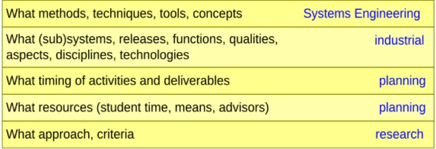
What methods, techniques, tools, concepts What (sub)systems, releases, functions, qualities, aspects, disciplines, technologies
Systems Engineering industrial
What timing of activities and deliverables planning
What resources (student time, means, advisors) planning
What approach, criteria research
Figure 4: Scoping is Crucial
The industrial environment is broad and complex, and the field of Systems Engineering is also quite broad. Scoping of the project is a crucial success factor. It is difficult to reach a specific result with some substance in a half year, if the scope of the project is broad.
Figure 4 shows that the project can be scoped in multiple dimensions. Core part of the scoping is what Systems Engineering methods and techniques will be researched and what industrial case will be used. The scope can be further fine-tuned by the project planning, resources and research method.
The student has to select what methods, techniques, tools or concepts will be applied, to scope the Systems Engineering content. Note that in general several methods and techniques will be used in the case, however, the focus of the research itself has to be more narrow. For example, in the industrial case requirements, selection matrices, functional models, use cases, and activity diagrams might be used, while the focus of the research is only on selection matrices.
The industrial supervisor and the student have to scope the case, by determining what component(s), what subsystem(s), what function(s), what qualities, aspects, disciplines and technologies belong to the case. For example, the case could be the control engineering part of the motion control component in the positioning subsystem.
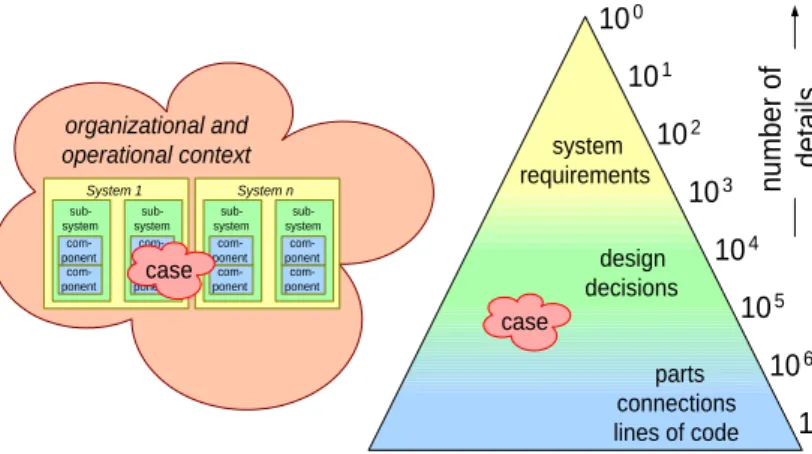
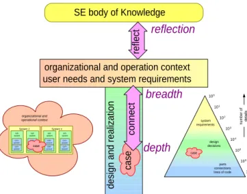
We have described the case positioning above in several dimensions. Figure 5 adds one more perspective on the case positioning: the level of abstraction or the amount of details taken into account.
Typical cases that have been scoped to fit the project needs address only part of the system, making the case somewhat remote from the system itself and the customer needs. Figure 6 shows that the breadth of Systems Engineering requires the student to link the case to the system requirements, the user needs and the
System n sub-system sub-system com-ponent com-ponent com-ponent com-ponent System 1 sub-system sub-system com-ponent com-ponent com-ponent com-ponent organizational and operational context case 100 101 106 105 104 103 102 107 system requirements design decisions parts connections lines of code number of details case
Figure 5: Case Positioning
organizational and operational contexts. The research part of the project is to reflect on this depth and breadth interaction in relation to the Systems Engineering Body of Knowledge.
Finally, Figure 7 shows that the industrial and academic interests are different: industrial interests are primarily to address the case, using Systems Engineering knowledge as means, while the academic interest is to extend and solidify the Systems Engineering Body of Knowledge, using the case as means.
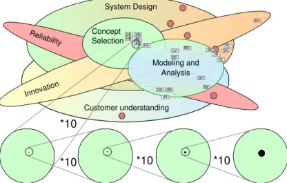
The research projects must also fit in the interests of the academic supervisor. The NISE Research Agenda, shown in Figure 8 from [2], provides some direction to select the Systems Engineering content and industrial case to fit in the NISE interests.
Figure 9 shows how the master projects of the first generations of master students map on the research agenda. The research agenda is shown different: as a Venn diagram. Every small rectangular box with two letter initials repre-sents the position of that specific master project. At the bottom of the diagram it is shown that every individual project is a very small contribution to the research area. However, the combination of many small projects helps to get a better under-standing of the research field, to see patterns, and to start validation across projects and domains.
Consequence of this approach is that the playing field is evolving. Tis emans that the yardstick for grading changes gradually. Newer projects build on previous projects.
100 101 106 105 104 103 102 107 system requirements design decisions parts connections lines of code number of details case organizational and operation context user needs and system requirements
design and realization
case
System n
sub-system system sub- com-ponent com-ponent com-ponent com-ponent System 1 sub-system system sub- com-ponent com-ponent com-ponent com-ponent organizational and operational context case connect SE body of Knowledge reflect depth breadth reflection
Figure 6: Depth, Breadth and Reflection
academic perspective
industrial perspective
organizational and operation context user needs and system requirements
design and realization
case connect SE body of Knowledge reflect depth breadth reflection
goal
means
goal
means
Systems Engineering features performance expectations number of products release cycle time
years months feature interaction complexity amount of software integration effort openness interoperability reliability trends consequences
hype and fashion
uncertainty time to market dev. cost overview globalization use globalization in development and logistics
dynamics
Reliability / Robustness in harsh environments Multi-disciplinary design
system modeling and analysis system design methods
Innovation
Responsiveness to change
change analysis Maritime capturing core know-how DR confidence level KA SW in system FMC capturing customer understanding KDA
shopfloor automation VAN
Figure 8: Buskerud Research Agenda
Customer understanding System Design Reliability Innovation Concept Selection Modeling and Analysis MD SA EH OL HB DK AE AK VN AT LV JR TL EE RK OK HR ES AR JB *10 *10 . *10 *10 .
3
Preparing and Performing the project
Figure 10 shows the entire process of preparing and executing the project. The first steps are to pick the subject for the project and to secure the advisors. Then the subject can be scoped, as described in Section 2.
Pick subject
Secure supervisors (NISE, industry)
Write proposal, project plan; for paper write abstract Perform project; involve supervisors regularly Write paper and iterate with supervisors Grading by academic supervisor and censor
Graduation Publication in journal or conference
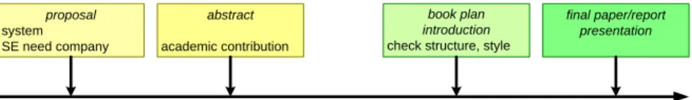
Figure 10: Process of Thesis Project The project is described in three single page deliverables:
proposal describing the project, the case, and the value for the industrial sponsor
plan showing the project time-line, activities, milestones, and their relations
abstract of the paper to delivered at the end of the project
[3] provides more background information on shaping this type of multi-disciplinary projects. proposal system SE need company abstract academic contribution book plan introduction check structure, style
final paper/report presentation
September November February May
tentative dates for milestones for IM students
Figure 11: Master Project Milestones
Figure reffig:SETPmilestones shows the main milestones in this process. The milestone dates are an indication. The master project coordinator will commu-nicate the exact dates. Student and academic supervisor have to agree on the abstract before the project itself can be started.
control system architecture and design
incremental build methematical models, simulate various inputs
analysis and simulation f2 analysis and simulation
f1
write draft paper and include findings finalize paper report layout
analyze stakeholders, requirements, analyze system
concepts and context
write phase report
"simple" context model, analyze system impact and adapt requirements verify system performance 70%-6wks 70%-1.5wks 50%-5wks 20%-5wks 20%-2wks 20%-11wks 20%-1wks 60%-2wks 10%-1wks 10%-1wks 10%-10wks 1 wk ~2 wks ~4 wks ~4 wks case (depth) system and context
(breadth) "meta" reflection and consolidation legend 70% 20% 10%
Figure 12: Plan: Simple PERT Diagram
We recommend to draw a simple and straightforward PERT plan [4]. An typical example for this type of projects is shown in Figure 12. In this plan we show the three main topics shown in Figure 6: the case specifics, the system and its context, and the reflection and research activities. Note that all these activities run concurrently. We recommend to use time-boxes of hours to days to manage this concurrency. The plan also shows that typically most time is spend in the case itself (about 70%), less time is spend on the system and its context (about 20%), and the time of actually reflecting and writing (the final delivery) is only about 10%.
"A good abstract should answer three questions: What did I do,
what did I learn, and why is that important?
The key is to identify something or things that can be reused in the future."
Prof. Michael Pennotti, Stevens Institute of Technology
Figure 13: Abstract
After scoping the project, and discussing it with the advisors, the next challenge is to write the abstract of the paper before the actual project start. Writing of the abstract forces the student to think and to be sharp about the research project its goal and the expected outcome. Figure 13 shows a quote from Prof Pennotti from SIT explaining what constitutes a good abstract.
The challenge in writing such abstract is that the student has to take the future perspective: imagining that the project has been finished. Figure 14 illustrates this ”time machine” that is needed to write the abstract. Note that the actual abstract in the final paper probably will be adapted to fit the actual findings. The students don’ have to fear that the abstract is fixed after writing this initial version.
time start project end project now abstract perspective "fast forward" yourself into the future
what do you expect to be the project outcome?
Students write an initial abstract at the start to think through what can happen. At the end of writing the paper, you write the real abstract. The academic supervisor has to accept
the initial abstract before starting the project.
Figure 14: Needed: Time Machine
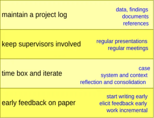
Once the project is approved the project execution can begin. Figure 15 gives a number of recommendation for the execution of the project:
maintain a project log during the entire project execution, from the early beginning onwards:
• Make bibliographic notes of papers, books, and other documentation
sources.
• Store all ”raw” data obtained by interviews, measurements, or any
other project activities.
maintain a project log data, findingsdocuments references
keep supervisors involved regular presentationsregular meetings
time box and iterate system and contextcase reflection and consolidation
early feedback on paper
start writing early elicit feedback early work incremental
• Archive intermediate results, such as presentations.
keep advisors involved by organizing regular meetings and presenting regularly
time box and iterate the different levels of activities in the project:
• the case work itself (depth)
• the system, user needs, and the organizational and operational contexts
(breadth)
• reflection and consolidation
elicit early feedback on the paper , start writing parts of the paper early and ask for feedback early and frequently from different stakeholders. Create the paper in an incremental way.
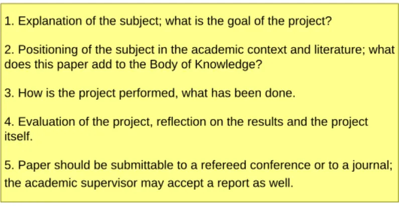
1. Explanation of the subject; what is the goal of the project?
2. Positioning of the subject in the academic context and literature; what does this paper add to the Body of Knowledge?
3. How is the project performed, what has been done.
4. Evaluation of the project, reflection on the results and the project itself.
5. Paper should be submittable to a refereed conference or to a journal; the academic supervisor may accept a report as well.
Figure 16: Publishable Paper
The final deliverable of the project and the main input for grading is the paper. The goal is to produce a paper that can be published at a conference or in a journal. Figure 16 shows what should be the content of the paper. Note that grading is a responsibility of SIT until BUC is accredited. Papers that are perceived to be publishable by the academic supervisors get an ”A” grade, else the grade will be ”B” or less.
Atwww.stevens.edu/sse/fileadmin/sse/pdf/SE_Master_Project_
Guidelines.pdfmore detailed guidelines can be found by SIT.
At the end of the master project, the student presents his master project. Figure reffig:SETPfinalPresentation shows the set-up of this presentation.
1. Clearly introduce the problem that the manuscript is discussing/ addressing,
2. Discuss the problem background. That is, discuss the research that has been previously conducted by you or others in the field (or related fields) to solve/address the same or similar problem,
3. Develop a succinct argument for the methods or ideas proposed in your manuscript,
4. Present a clear and understandable justification of why the proposed methods or ideas contribute to a superior or different solution to the problem. A clear statement of your contributions is often crucial to reviewers. Clear specify this when possible. And finally,
5. Discuss the likely future directions of the research being conducted by you (your group).
www.stevens.edu/sse/fileadmin/sse/pdf/SE_Master_Project_Guidelines.pdf
Figure 17: Stevens Guidelines for Paper
4
Publication
We intend to publish the paper in a journal or at a conference. The student is the first author of the paper, the academic supervisor(s) are second and third author. Publication takes time and practically takes place after graduation. Figure 19 shows the publication process.
If a third party is involved, e.g. a customer or supplier, then ask the third party to agree with publication procedure:
http://www.gaudisite.nl/BuskerudSEpublicationProcedureSlides.
pdf, and ask who will be reviewer for the third party.
5
Practicalities
We do have a set of conventions to more easily manage the stream of artifacts produced during the preparation and the execution of the project, see Figure 20.
We assume that all communication of artifacts takes place electronically. All filenames should follow the conventions shown in Figure 20, the concatenation of
the abbreviationSEMP(Systems Engineering Master Project), thestudents name
(first name, family name), thesubject(e.g. proposal, abstract, plan, presentation,
paper),dot,version,dot extension.
The file type should be reasonably standard, e.g. pdf, jpeg, or one of the file formats that can be read both by Microsoft Office as well as OpenOffice (doc, docx, xls, xlsx, ppt, pptx). Exotic formats, such as Microsoft Projects, only after approval by the advisors.
student presentation of master project ~30 minutes presentation
~20 minutes questioning by examinators ~10 minutes examinators conclude committee:
· academic supervisor
· at least one other academic staff member of SE · (optional) censor
· (optional) company supervisor or representative · at least 3 people
Figure 18: Final Presentation at the end of the project
subject should again contain the abbreviation SEMP and the subject.
6
Acknowledgements
This document has been written with inputs from Stevens Institute, especially Mike Pennotti, and from Gunnar Berge. The first cohorts of studnets doing their master project helped to shape this document.
7
Links
Figure reffig:SETPlinks provides links to websites with more relevant information.
References
[1] Gerrit Muller. The system architecture homepage. http://www.
gaudisite.nl/index.html, 1999.
[2] Gerrit Muller. Buskerud university program systems engineering. http:
//www.gaudisite.nl/BuskerudAgendaPaper.pdf, 2008.
[3] Gerrit Muller. A multi-disciplinary research approach,
illus-trated by the boderc project. http://www.gaudisite.nl/
Company screens paper for sensitive or confidential issues, see http://www.gaudisite.nl/BuskerudSEpublicationProcedureSlides.pdf Select target journal or conference, typical choices are:
INCOSE symposium, CSER, Journal of SE
Transform the paper into the prescribed format or template Review of the paper by NISE and Company, adapt paper Submit paper to journal or conference
Process journal or conference feedback Final review by company
Submit final version
Visit conference and present paper
Figure 19: Publication Process
[4] NetMBA.com. Topics in project management: PERT. http://www.
netmba.com/operations/project/pert/, 2007.
History
Version: 1.6, date: June 8, 2015 changed by: Gerrit Muller
• added criteria
• removed research agenda
Version: 1.5, date: September 8, 2014 changed by: Gerrit Muller
• links for September workshop
Version: 1.4, date: March 18, 2014 changed by: Gerrit Muller
• added milestones
• added brief text about presentation
Version: 1.3, date: June 12, 2013 changed by: Gerrit Muller
• added formalized goals
• adapted the text in the paper accordingly
• updated stakeholders figure
• used term supervisor more consistently
• explained the goal of the initial abstract
• added final presentation
• updated links
Version: 1.2, date: August 24, 2012 changed by: Gerrit Muller
• slide with links
Version: 1.1, date: August 20, 2010 changed by: Gerrit Muller
• added publication to process
• added slide about publication
• added third party slide
• removed alternative project report
• added map of research projects
• removed paragraph in introduction about the relation Stevens and BUC
• changed status to concept
Version: 1.0, date: February 3, 2009 changed by: Gerrit Muller
• made a paper version
• changed status to draft
Version: 0.3, date: February 2, 2009 changed by: Gerrit Muller
• added submission instructions
Version: 0.2, date: January 29, 2009 changed by: Gerrit Muller
Submission instructions
use for all deliverables the following conventions:
filename: SEMP <your name> <subject>.<version>.<extension>
e.g. SEMP John Student abstract.2.doc
where subject = {proposal | abstract | plan | presentation | paper | ...}
email to:
subject: SEMP <subject> cc:
"standard" file types preferred, e.g. pdf, jpg, doc, xls, ppt <gerrit muller gmail com>
<gunnarkb gmail com>
Figure 20: Conventions for Submitting Project Deliverables
• added PET plan
• added abstract explanation
• changed title
Version: 0.1, date: January 26, 2009 changed by: Gerrit Muller
• added figures to position case and project work
Version: 0, date: May 23, 2008 changed by: Gerrit Muller
workshop 1 in June
Master Project Description: http://www.gaudisite.nl/SEthesisProjectPaper.pdf
workshop 2 in August
Systems Engineering Research Methods: http://www.gaudisite.nl/SEresearchMethodsSlides.pdf
workshop 3 in September
Master Project; Writing an Abstract: http://www.gaudisite.nl/MasterProjectWritingAnAbstract.pdf
Master Project; Execution Phase: http://www.gaudisite.nl/MasterProjectProjectExecution.pdf
Publication procedure: http://www.gaudisite.nl/BuskerudSEpublicationProcedureSlides.pdf
Guidelines for visualizations: http://www.gaudisite.nl/VisualizationGuidelinesSlides.pdf
Validation of Systems Engineering Methods and Techniques in Industry
http://www.gaudisite.nl/CSER2012_Muller_validationSEinIndustry.pdf
Systems Engineering Research Methods (paper)
http://www.gaudisite.nl/CSER2013_Muller_SEresearchMethods.pdf
Systems Engineering Research Validation http://www.gaudisite.nl/SEresearchValidationPaper.pdf
Published Master Project papers: http://www.gaudisite.nl/MasterProjectPapers.html
Workshop Academic Writing http://www.gaudisite.nl/RPacademicWritingSlides.pdf
Stevens Institute guidelines: https://www.stevens.edu/mpt/content/masters-project-guidelines