ISG
Instantaneous System and Software Generation
AUTOMATED SYSTEM DOCUMENTATION
OF
USER INPUTS
(Date: Tue Apr 13 12:28:24 2004)
Rainer Gerlich
BSSE System and Software Engineering Auf dem Ruhbuehl 181
88090 Immenstaad Germany Phone: +49/7545/91.12.58 Mobile: +49/171/80.20.659 Fax: +49/7545/91.12.40 e-mail: [email protected] www: http://www.bsse.biz
TABLE OF CONTENTS
1 OVERVIEW ON COMMUNICATION, TOPOLOGY AND DISTRIBUTION
1.1 Process Communication Summary
Fig. 1: Process Communication Summary
1.2 Process Communication of Process Instances
Fig. 2: Process Communication of Process Instances
1.3 Platform Information
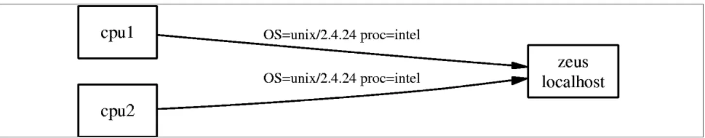
1.4 Information on Distribution of Application
Fig. 4: Information on Distribution of Application
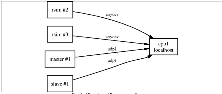
1.5 Allocation of Resources to Processes
Fig. 5: Allocation of Resources to Processes
2 DATA FLOW OF PROCESSES
2.1 Process master
2.1.1 State processinit
2.1.1.1 Message poweron
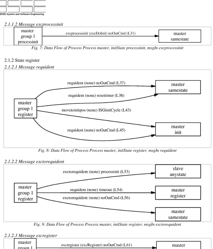
2.1.1.2 Message excprocessinit
Fig. 7: Data Flow of Process Process master, initState processinit, msgIn excprocessinit
2.1.2 State register
2.1.2.1 Message requident
Fig. 8: Data Flow of Process Process master, initState register, msgIn requident
2.1.2.2 Message exctorequident
Fig. 9: Data Flow of Process Process master, initState register, msgIn exctorequident
2.1.2.3 Message excregister
2.1.3 State init
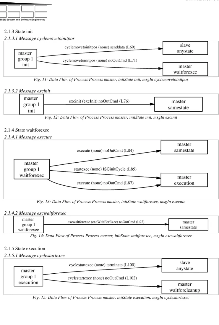
2.1.3.1 Message cyclemovetoinitpos
Fig. 11: Data Flow of Process Process master, initState init, msgIn cyclemovetoinitpos
2.1.3.2 Message excinit
Fig. 12: Data Flow of Process Process master, initState init, msgIn excinit
2.1.4 State waitforexec
2.1.4.1 Message execute
Fig. 13: Data Flow of Process Process master, initState waitforexec, msgIn execute
2.1.4.2 Message excwaitforexec
Fig. 14: Data Flow of Process Process master, initState waitforexec, msgIn excwaitforexec
2.1.5 State execution
2.1.5.1 Message cyclestartexec
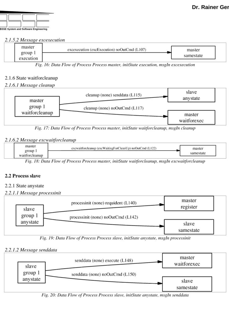
2.1.5.2 Message excexecution
Fig. 16: Data Flow of Process Process master, initState execution, msgIn excexecution
2.1.6 State waitforcleanup
2.1.6.1 Message cleanup
Fig. 17: Data Flow of Process Process master, initState waitforcleanup, msgIn cleanup
2.1.6.2 Message excwaitforcleanup
Fig. 18: Data Flow of Process Process master, initState waitforcleanup, msgIn excwaitforcleanup
2.2 Process slave
2.2.1 State anystate
2.2.1.1 Message processinit
Fig. 19: Data Flow of Process Process slave, initState anystate, msgIn processinit
2.2.1.2 Message senddata
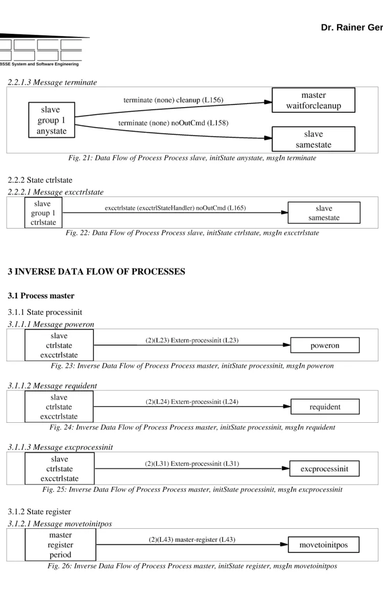
2.2.1.3 Message terminate
Fig. 21: Data Flow of Process Process slave, initState anystate, msgIn terminate
2.2.2 State ctrlstate
2.2.2.1 Message excctrlstate
Fig. 22: Data Flow of Process Process slave, initState ctrlstate, msgIn excctrlstate
3 INVERSE DATA FLOW OF PROCESSES
3.1 Process master
3.1.1 State processinit
3.1.1.1 Message poweron
Fig. 23: Inverse Data Flow of Process Process master, initState processinit, msgIn poweron
3.1.1.2 Message requident
Fig. 24: Inverse Data Flow of Process Process master, initState processinit, msgIn requident
3.1.1.3 Message excprocessinit
Fig. 25: Inverse Data Flow of Process Process master, initState processinit, msgIn excprocessinit
3.1.2 State register
3.1.2.1 Message movetoinitpos
3.1.2.2 Message exctorequident
Fig. 27: Inverse Data Flow of Process Process master, initState register, msgIn exctorequident
3.1.2.3 Message excregister
Fig. 28: Inverse Data Flow of Process Process master, initState register, msgIn excregister
3.1.3 State init
3.1.3.1 Message cyclemovetoinitpos
Fig. 29: Inverse Data Flow of Process Process master, initState init, msgIn cyclemovetoinitpos
3.1.3.2 Message excinit
Fig. 30: Inverse Data Flow of Process Process master, initState init, msgIn excinit
3.1.4 State waitforexec
3.1.4.1 Message execute
Fig. 31: Inverse Data Flow of Process Process master, initState waitforexec, msgIn execute
3.1.4.2 Message startexec
Fig. 32: Inverse Data Flow of Process Process master, initState waitforexec, msgIn startexec
3.1.4.3 Message excwaitforexec
3.1.5 State execution
3.1.5.1 Message cyclestartexec
Fig. 34: Inverse Data Flow of Process Process master, initState execution, msgIn cyclestartexec
3.1.5.2 Message excexecution
Fig. 35: Inverse Data Flow of Process Process master, initState execution, msgIn excexecution
3.1.6 State waitforcleanup
3.1.6.1 Message cleanup
Fig. 36: Inverse Data Flow of Process Process master, initState waitforcleanup, msgIn cleanup
3.1.6.2 Message excwaitforcleanup
Fig. 37: Inverse Data Flow of Process Process master, initState waitforcleanup, msgIn excwaitforcleanup
3.2 Process slave
3.2.1 State anystate
3.2.1.1 Message processinit
Fig. 38: Inverse Data Flow of Process Process slave, initState anystate, msgIn processinit
3.2.1.2 Message senddata
Fig. 39: Inverse Data Flow of Process Process slave, initState anystate, msgIn senddata
3.2.1.3 Message terminate
3.2.2 State ctrlstate
3.2.2.1 Message excctrlstate
Fig. 41: Inverse Data Flow of Process Process slave, initState ctrlstate, msgIn excctrlstate
4 DETAILED STATE TRANSITIONS
4.1 Process master
Fig. 42: Detailed State Transitions of Process Process master
5 SUMMARY OF STATE TRANSITIONS
5.1 Process master
Fig. 44: Summary of State Transitions of Process Process master
5.2 Process slave
Fig. 45: Summary of State Transitions of Process Process slave
6 COMPLETE DATA FLOW OF THE SYSTEM
7 HIERACHY OF FUNCTIONS
7.1 Process master
7.1.1 State Caller-Called Relationship
7.1.1.1 Message Calling Function gu_TYMASTEROPS_execstatecommandmaster
Fig. 47: Caller-Called Relationship of Process master, Calling Function gu_TYMASTEROPS_execstatecommandmaster
7.1.1.2 Message Calling Function gu_TYMASTEROPS_execglobcommandmaster
Fig. 48: Caller-Called Relationship of Process master, Calling Function gu_TYMASTEROPS_execglobcommandmaster
7.1.1.4 Message Calling Function master_processinit_excprocessinit
Fig. 50: Caller-Called Relationship of Process master, Calling Function master_processinit_excprocessinit
7.1.1.5 Message Calling Function master_register_excregister
Fig. 51: Caller-Called Relationship of Process master, Calling Function master_register_excregister
7.1.1.6 Message Calling Function master_init_excinit
Fig. 52: Caller-Called Relationship of Process master, Calling Function master_init_excinit
7.1.1.7 Message Calling Function master_waitforexec_excwaitforexec
Fig. 53: Caller-Called Relationship of Process master, Calling Function master_waitforexec_excwaitforexec
7.1.1.8 Message Calling Function master_execution_excexecution
Fig. 54: Caller-Called Relationship of Process master, Calling Function master_execution_excexecution
7.1.1.9 Message Calling Function master_waitforcleanup_excwaitforcleanup
Fig. 55: Caller-Called Relationship of Process master, Calling Function master_waitforcleanup_excwaitforcleanup
7.1.1.10 Message Calling Function masterreceiveUDP
Fig. 56: Caller-Called Relationship of Process master, Calling Function masterreceiveUDP
7.1.1.11 Message Calling Function main
7.1.2 State Called-Caller Relationship
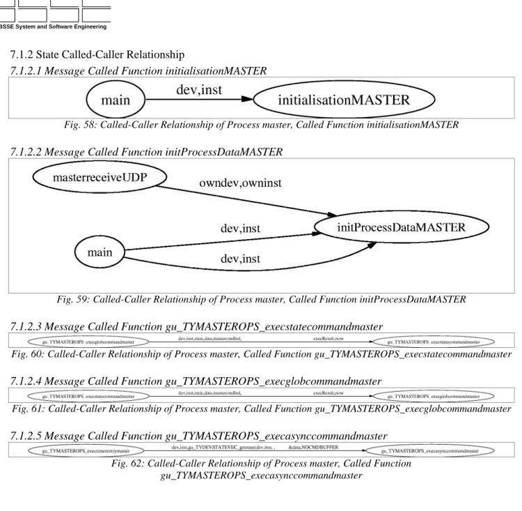
7.1.2.1 Message Called Function initialisationMASTER
Fig. 58: Called-Caller Relationship of Process master, Called Function initialisationMASTER
7.1.2.2 Message Called Function initProcessDataMASTER
Fig. 59: Called-Caller Relationship of Process master, Called Function initProcessDataMASTER
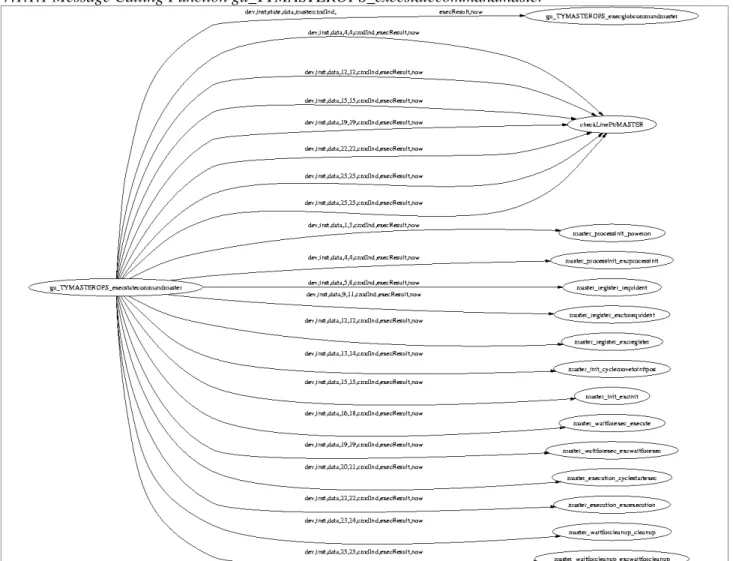
7.1.2.3 Message Called Function gu_TYMASTEROPS_execstatecommandmaster
Fig. 60: Called-Caller Relationship of Process master, Called Function gu_TYMASTEROPS_execstatecommandmaster
7.1.2.4 Message Called Function gu_TYMASTEROPS_execglobcommandmaster
Fig. 61: Called-Caller Relationship of Process master, Called Function gu_TYMASTEROPS_execglobcommandmaster
7.1.2.5 Message Called Function gu_TYMASTEROPS_execasynccommandmaster
Fig. 62: Called-Caller Relationship of Process master, Called Function gu_TYMASTEROPS_execasynccommandmaster
7.1.2.6 Message Called Function checkLinePtrMASTER
Fig. 63: Called-Caller Relationship of Process master, Called Function checkLinePtrMASTER
7.1.2.7 Message Called Function master_processinit_poweron
Fig. 64: Called-Caller Relationship of Process master, Called Function master_processinit_poweron
7.1.2.8 Message Called Function master_processinit_excprocessinit
Fig. 65: Called-Caller Relationship of Process master, Called Function master_processinit_excprocessinit
7.1.2.9 Message Called Function master_register_requident
Fig. 66: Called-Caller Relationship of Process master, Called Function master_register_requident
7.1.2.10 Message Called Function master_register_exctorequident
Fig. 67: Called-Caller Relationship of Process master, Called Function master_register_exctorequident
7.1.2.11 Message Called Function master_register_excregister
Fig. 68: Called-Caller Relationship of Process master, Called Function master_register_excregister
7.1.2.12 Message Called Function master_init_cyclemovetoinitpos
7.1.2.13 Message Called Function master_init_excinit
Fig. 70: Called-Caller Relationship of Process master, Called Function master_init_excinit
7.1.2.14 Message Called Function master_waitforexec_execute
Fig. 71: Called-Caller Relationship of Process master, Called Function master_waitforexec_execute
7.1.2.15 Message Called Function master_waitforexec_excwaitforexec
Fig. 72: Called-Caller Relationship of Process master, Called Function master_waitforexec_excwaitforexec
7.1.2.16 Message Called Function master_execution_cyclestartexec
Fig. 73: Called-Caller Relationship of Process master, Called Function master_execution_cyclestartexec
7.1.2.17 Message Called Function master_execution_excexecution
Fig. 74: Called-Caller Relationship of Process master, Called Function master_execution_excexecution
7.1.2.18 Message Called Function master_waitforcleanup_cleanup
Fig. 75: Called-Caller Relationship of Process master, Called Function master_waitforcleanup_cleanup
7.1.2.19 Message Called Function master_waitforcleanup_excwaitforcleanup
Fig. 76: Called-Caller Relationship of Process master, Called Function master_waitforcleanup_excwaitforcleanup
7.1.2.20 Message Called Function excDoInit
Fig. 77: Called-Caller Relationship of Process master, Called Function excDoInit
7.1.2.21 Message Called Function excRegister
Fig. 78: Called-Caller Relationship of Process master, Called Function excRegister
7.1.2.22 Message Called Function excInit
Fig. 79: Called-Caller Relationship of Process master, Called Function excInit
7.1.2.24 Message Called Function excExecution
Fig. 81: Called-Caller Relationship of Process master, Called Function excExecution
7.1.2.25 Message Called Function excWaitingForCleanUp
Fig. 82: Called-Caller Relationship of Process master, Called Function excWaitingForCleanUp
7.1.3 State Complete Function Hierachy of Process master
Fig. 83: Function Hierachy of Process master
7.2 Process slave
7.2.1 State Caller-Called Relationship
7.2.1.1 Message Calling Function gu_TYSLAVEOPS_execstatecommandslave
Fig. 84: Caller-Called Relationship of Process slave, Calling Function gu_TYSLAVEOPS_execstatecommandslave
7.2.1.2 Message Calling Function gu_TYSLAVEOPS_execglobcommandslave
7.2.1.3 Message Calling Function gu_TYSLAVEOPS_exectimerentryslave
Fig. 86: Caller-Called Relationship of Process slave, Calling Function gu_TYSLAVEOPS_exectimerentryslave
7.2.1.4 Message Calling Function slave_ctrlstate_excctrlstate
Fig. 87: Caller-Called Relationship of Process slave, Calling Function slave_ctrlstate_excctrlstate
7.2.1.5 Message Calling Function slavereceiveUDP
Fig. 88: Caller-Called Relationship of Process slave, Calling Function slavereceiveUDP
7.2.1.6 Message Calling Function main
Fig. 89: Caller-Called Relationship of Process slave, Calling Function main
7.2.2 State Called-Caller Relationship
7.2.2.1 Message Called Function initialisationSLAVE
Fig. 90: Called-Caller Relationship of Process slave, Called Function initialisationSLAVE
7.2.2.3 Message Called Function gu_TYSLAVEOPS_execstatecommandslave
Fig. 92: Called-Caller Relationship of Process slave, Called Function gu_TYSLAVEOPS_execstatecommandslave
7.2.2.4 Message Called Function gu_TYSLAVEOPS_execglobcommandslave
Fig. 93: Called-Caller Relationship of Process slave, Called Function gu_TYSLAVEOPS_execglobcommandslave
7.2.2.5 Message Called Function gu_TYSLAVEOPS_execasynccommandslave
Fig. 94: Called-Caller Relationship of Process slave, Called Function gu_TYSLAVEOPS_execasynccommandslave
7.2.2.6 Message Called Function checkLinePtrSLAVE
Fig. 95: Called-Caller Relationship of Process slave, Called Function checkLinePtrSLAVE
7.2.2.7 Message Called Function slave_anystate_processinit
Fig. 96: Called-Caller Relationship of Process slave, Called Function slave_anystate_processinit
7.2.2.8 Message Called Function slave_anystate_senddata
Fig. 97: Called-Caller Relationship of Process slave, Called Function slave_anystate_senddata
7.2.2.9 Message Called Function slave_anystate_terminate
Fig. 98: Called-Caller Relationship of Process slave, Called Function slave_anystate_terminate
7.2.2.10 Message Called Function slave_ctrlstate_excctrlstate
Fig. 99: Called-Caller Relationship of Process slave, Called Function slave_ctrlstate_excctrlstate