A design environment for mobile applications
Stephen Gilmore
Valentin Haenel
Jane Hillston
Jennifer Tenzer
Laboratory for Foundations of Computer Science,
The University of Edinburgh, Scotland.
Abstract
In this paper we show how high-level UML models of mobile computing applications can be analysed for clas-sical performance measures such as throughput. The approach proceeds by compiling the UML model into a representation in the formally-defined modelling language of PEPA nets. The compilation process and subsequent performance analysis based on numerical solution of a Continuous-Time Markov Chain is supported by a software tool, the Choreographer design platform. Choreographer interoperates with popular UML tools by reading and writ-ing UML models in the XML Metadata Interchange format (XMI).
1
Introduction
Mobile code and mobile computing applications pro-vide some of the most difficult implementation challenges for application developers today. Mobile code applica-tions must be robust against changing execution environ-ments and computing platforms [18] and may be expected to work with low bandwidth, intermittently unavailable net-work connections. Mobile computing offers further chal-lenges because mobile computing devices are typically weak computing devices such as PDAs and telephones. It has additional concerns unknown in the immobile comput-ing application area, such as the need to conserve battery energy [12]. In this paper we considermobilityin its broad-est sense; amobile applicationis one for which the compu-tational environment may change over a typical run of the application. This encompasses both physical movement of the device on which the application runs and code which migrates between devices.
Theoretical computer science has addressed the prob-lems of development of mobile applications by the creation of formal languages which are used to study essential prop-erties of mobility such as the management of names, the
acquisition of new capabilities (or loss of existing ones) and movement of the locus of computation. Sometimes mobility is expressed via other ideas, believed to be more primitive and hence more fundamental, such as the name passing and channel passing used in the π-calculus [33]. Another approach is to represent code movement with a metaphor such as the nested named containers used to repre-sent authorisation domains in the ambient calculus [11]. In the PEPA nets approach [23] mobility is represented more literally by the passing of objects with behaviour as the tokens of a coloured Petri net. The PEPA nets language and others such as the Stochasticπ-calculus [38] have the addi-tional benefit that they are quantified modelling languages which can be used for performance analysis of systems in addition to determining behavioural properties such as free-dom from deadlock. For mobile computing the quantita-tive information is especially relevant: small devices do not have plentiful computing capacity so describing resource consumption and predicting resource-related problems is particularly helpful.
Software engineers have also responded to the challenge of developing mobile applications. A number of design notations which explicitly capture mobility have been intro-duced, for example [4, 30, 17, 35, 3], many of them based on the Unified Modelling Language.
Contribution of this paper In this paper we present a
software tool which makes rigorous quantitative analysis of mobile application designs accessible via a high-level design notation. Specifically we extract a PEPA net model from a UML activity diagram, analyse the PEPA net and report the results back as a modified activity diagram.
1.1
Related Work
One idea to connect the high-level models used by modellers with the low-level implementations produced by developers might be to try to interface with software devel-opment directly by converting stochastic process models 1
into programs [21], or programs into stochastic process models.
Space limitations preclude a comprehensive treatment of related work here so we highlight only a few works in the related literature. Our present work builds on our earlier work on mapping UML activity diagrams to process alge-bras [9]. Other works have targeted different performance analysis methods [15]. A closely related approach to ours is taken in [37], in the UML-based performance analysis of a Web-based micro-business service.
Other authors take the approach of modifying the UML notation in order to express the properties of greatest inter-est, by they mobility [3] or performance-related [27]. While the reason for these extensions is evident and appealing, the significant loss is that the modified UML can no longer be processed with the UML tools. Thus, we have been able to interoperate with standard, unaltered UML tools whereas others cannot.
Our analysis tools operate via the numerical solution of Markov chains, with all of the advantages and disad-vantages which this approach entails (exact solution is an advantage, susceptibility to state-space explosion a disad-vantage). Simulation has quite different analysis charac-teristics (approximate solutions require the calculation of confidence intervals, but large state-space size is tolerated) meaning that the approach to simulation of UML models taken in UML-Ψcould complement ours well.
Structure of this paper: In Section 2 we present the
UML-based design notation and the PEPA net performance modelling formalism. Section 3 describes how UML con-structs are mapped into the concon-structs of the PEPA nets modelling language. Section 4 discusses the Choreographer design platform. Section 5 presents an example. Future work and conclusions follow in Section 6.
2
Modelling mobility
2.1
Modelling mobility in UML
The Unified Modelling Language (UML) is a collection of diagrammatic notations for documenting the design of software systems. It has been widely adopted in industry and extensively studied by software engineers. Numerous extensions to the notations have been proposed to tailor the technique to systems with particular characteristics. Specif-ically, several groups have proposed extensions which aim to capture the pertinent properties of mobile applications, e.g. [4, 30, 35, 29, 3].
We follow the approach to the representation of mobil-ity developed by Baumeister et al. within the AGILE project [3, 2]. This approach is focussed on activity dia-grams. As the name suggests, the main objective of an
activity diagram is to capture the activities which are under-taken within the system, recording the temporal and causal relationships between them. Thus activities are connected to each other via control transitions. In addition, anobject, with state, may be related to an activity, indicating that the given object is required for the successful completion of the activity. Moreover, an activity may be related to a stateful object, indicating that the object is in the given the state as a result of the activity.
In the approach of Baumeisteret al.state changes that are a change of location are distinguished: activities which result in an object changing location are decorated with the stereotypemove. Furthermore, each object box is dec-orated with the tagatLoc =·, which indicates the loca-tion of the object at that point within the sequence of activ-ities.
We illustrate the notation with a simple example. Con-sider a text file and the activities associated with it. Figure 1 shows an activity diagram representing these activities. The file may either be opened for reading or for writing. This choice may be represented explicitly by a decision diamond (as here) or implicitly by having two alternative transitions emanating from the previous activity (which would be the start marker in this case). Once the file is opened appro-priately, the corresponding operation can take place. That operation must be completed before the file is closed. The file object is required for each of the activities depicted in the diagram. Moreover we would expect the state of the file to be changed by all of the activities exceptread.
start marker decision diamond f: FILE f’: FILE f’: FILE f’’: FILE f: FILE f*: FILE f**: FILE f***: FILE openRead read close openWrite write close activity object
Figure 1. Activity diagram (without mobility) showing the activities available on a file
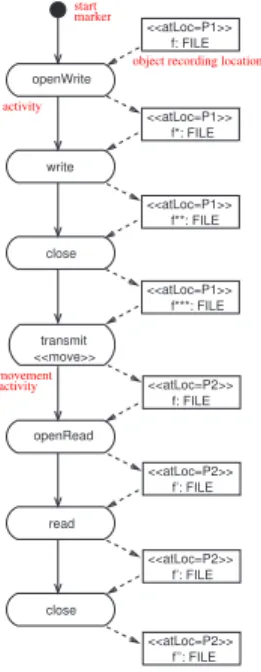
To see the additional notation introduced by Baumeis-teret al.we consider a variation on this activity diagram in which the file considered is a SMS or instant message. In this case the file must be first written, then transmittedto a
new location, before being read. The corresponding activ-ity diagram is shown in Figure 2. Thetransmitactivity is clearly distinguished as the one which causes a movement, and this is reflected in the location of the file before and after the activity.
start marker openWrite write <<move>> transmit openRead read f: FILE <<atLoc=P1>> close close f*: FILE <<atLoc=P1>> f**: FILE <<atLoc=P1>> f***: FILE <<atLoc=P1>> f: FILE <<atLoc=P2>> f’: FILE <<atLoc=P2>> f’: FILE <<atLoc=P2>> f’’: FILE <<atLoc=P2>> activity movement activity
object recording location
Figure 2. Activity diagram showing the activ-ities available on an instant message file
2.2
Performance modelling of mobility
In this section we provide a brief overview of PEPA nets and the PEPA stochastic process algebra. A fuller descrip-tion is available in [23] and [26].
The tokens of a PEPA net are terms of the PEPA stochas-tic process algebra which define the behaviour of compo-nents via the activities they undertake and their interactions. One example of a PEPA component would be aFileobject which can be opened for reading or writing, have data read (or written) and closed. Such an object would understand the methodsopenRead(), openWrite(),read(), write() and close().
File = (openReaddef ,ro).InStream
+ (openWrite,ro).OutStream
InStream = (def read,rr).InStream+ (close,rc).File
OutStream = (def write,rw).OutStream+ (close,rc).File This PEPA model documents a high-level protocol for using Fileobjects, from which it is possible to derive properties such as “it is not possible to write to a closed file” and “read
and write operations cannot be interleaved: the file must be closed and re-opened first”.
Every activity incurs an execution cost which is quanti-fied by an estimate of the (exponentially-distributed) rate at which it can occur (ro, rr, rw, rc). Activities may be
passive, i.e. they can be executed only in cooperation with corresponding active ones. The rate of a passive activity is denoted by.
A PEPA net is made up of PEPAcontexts, one at each place in the net. A context consists of a number ofstatic components (possibly zero) and a number ofcells(at least one). Like a memory location in an imperative program, a cell is a storage area to be filled by a datum of a particular type. In particular in a PEPA net, a cell is a storage area dedicated to storing a PEPA component, such as the File object described above. The components which fill cells can circulate as the tokens of the net. In contrast, the static components cannot move. A typical place might be the fol-lowing:
File[ ]
L FileReader
where the synchronisation set L in this case is A(File), thecomplete action type setof the component, (openRead, openWrite, . . . ). This place has aFile-type cell and a static component,FileReader, which can process the file when it arrives.
A PEPA net differentiates between two types of change of state. We refer to these asfiringsof the net and transi-tionsof PEPA components. Each are special cases of PEPA activities. Transitions of PEPA components will typically be used to model small-scale (orlocal) changes of state as components undertake activities. Firings of the net will typ-ically be used to model macro-step (orglobal) changes of state such as context switches, breakdowns and repairs, one thread yielding to another, or a mobile software agent mov-ing from one network host to another. The set of all fir-ings is denoted byAf, the set of all transitions byAt. We distinguish firings syntactically by printing their names in boldface.
Continuing our example, we introduce an instant mes-sage as a type of transmissible file.
InstantMessage= (def transmit,rt).File
Part of a definition of a PEPA net which models the passage of instant messages is shown below. An instant messageIM can be moved from the input place on the left to the output place on the right by thetransmitfiring1. In doing so it changes state to evolve to aFile derivative, which can be 1Unconventionally our places are depicted by rectangles in this
exam-ple for ease of including the token, cell and static component associated with the places.
read by theFileReader.
InstantMessage[IM]
(transmit,rt)
−−−→ −−−→File[ ]
L FileReader The syntax of PEPA nets is given in Figure 3. S denotes a sequential component and P a concurrent component which executes in parallel. I stands for a constant denot-ing either a sequential or a concurrent component, as bound by a definition.
N ::= D+M (net)
M ::= (MP, . . .) (marking)
MP ::= P[C, . . .] (place marking)
D ::= I=defS (component defn)
| P[C]=defP[C] (place defn)
| P[C, . . .]=defP[C]
L P (place defn)
P ::= P
L P (cooperation) | P/L (hiding) | P[C] (cell) | I (identifier) C ::= ‘ ’ (empty) | S (full) S ::= (α,r).S (prefix) | S+S (choice) | I (identifier)
Figure 3. The syntax of PEPA nets
Definition 1 (PEPA net) A PEPA net N is a tuple N =
(P,T,I,O,,π,C,D,M0) such that • Pis a finite set of places; • T is a finite set of net transitions; • I:T → Pis the input function; • O:T → Pis the output function;
• : T → (Af,R+ ∪ {}) is the labelling func-tion, which assigns a PEPA activity ((type, rate) pair) to each transition. The rate determines the negative exponential distribution governing the delay associ-ated with the transition;
• π : Af → Nis the priority function which assigns priorities (represented by natural numbers) to firing action types;
• C : P → P is the place definition function which assigns a PEPA context, containing at least one cell, to each place;
• Dis the set of token component definitions; • M0is the initial marking of the net.
The structured operational semantics, defined in [23], give a precise definition of the possible evolution of a PEPA net, and shows how a CTMC can be derived, treating each marking as a distinct state.
We define the firing rule of PEPA nets to respect the net structure in the usual way (one token from each input place, one token to each output place) but also to take into con-sideration the ability of tokens to participate in the firing (can they perform an activity of the correct type?), and the availability of vacant cells of the appropriate type in the out-put places. Note that we require that the net isbalancedin the sense that, for each transition, the number of input cells is equal to the number of output cells. In classical Petri nets tokens are identitiless, and can be viewed as being con-sumed from input places and created into output places for each firing. In contrast, in PEPA nets our tokens have state and identity, and we view them aspassing throughnet-level transitions. For each firing there must be as many output tokens as there were input tokens.
Definition 2 (Enabling) An enabling is a mapping of
places to tokens. A net level transition t has anenabling of firing typeα,E(t,α), if for each input placePiof t there
is a token T in the current marking of Pi, which has a
one-stepα-derivative, T.
Note that there may be several enablings for a given transition firing in any particular marking, as the enabling selects one token to fire from each input place, and there may be more than one eligible token at each input place.
Since it is important that each fired token has a vacant cell to go into after the firing, we define a corresponding notion ofoutput. A transition has an output if, in the cur-rent marking, there is at least one vacant cell in each output place.
Definition 3 (Output) For any net level transition t, an
output, denotedO(t), is a mapping from the output places of t to vacant cells in the current marking.
Since each token passes through a net level transition when it fires, such a transition is enabled only when there is a bijective function between the chosen enabling and an output.
Definition 4 (Concession) A net level transition t has
con-cessionfor a firing of typeαif there is an enablingE(t,α) such that there is a bijective mappingφfromE(t,α)to an outputO(t), which preserves the types of tokens.
As with classical Petri nets with priority, having con-cession identifies those transitions which could legally fire
according to the net structure and the current marking. The set of transitions whichcanfire is determined by the priori-ties.
Definition 5 (Enabling Rule) A net level transition t will
be enabled for a firing of type αif there is no other net transition of higher priority with concession in the current marking.
Definition 6 (Firing Rule) When a net level transition t
fires with typeαon the basis of the enablingE(t,α), and concession φ then for each (Pi, T,) in E(t, α), T[T] is
replaced by T[ ] in the marking of Pi, and the current
marking of each output place is updated according toφ. We assume that when there is more than one mappingφ from an enabling to an output, then they have equal proba-bility and one is selected randomly. The rate of the enabled firing is determined using apparent rates, and the notion of bounded capacity, as usual for PEPA. We refer the reader to [22] for more details.
3
Mapping
In this section we give describe the mapping from mobil-ity UML activmobil-ity diagrams developed by Baumeisteret al.to PEPA nets. As we have seen in the PEPA net the places of the Petri net correspond to the different locations or compu-tational contexts present in the system, while the transitions correspond to state changes which result in a different dis-tribution of computational elements across contexts.
The UML activity diagrams which we consider clearly exhibit both locations and movements — these correspond to places and transitions at the net level of the PEPA net. Therefore the first step of our mapping is to create a net in which there is one place for each location which appears on the right hand side of anatLoc =·tag in the activ-ity diagram. Second, we create a net level transition corre-sponding to eachmove. Such a transition will have an input arc corresponding to each object flow into the activity and an output arc for each object flow out of the activity. Moreover the places connected to these arcs are determined by the locations of the corresponding objects. This com-pletes the net level definition of the PEPA net, but it remains to instantiate the PEPA equations which define the tokens of the PEPA nets and the static components specifying the contexts associated with each place.
The tokens of the PEPA net correspond to the objects of the activity diagram: we define one token for each object. The activities which the token undertakes are defined by the structure of the activity diagram, disregarding activities which do not involve this object, i.e. which do not have an association with this object. Each activity in the activity diagram is mapped to an activity in the PEPA definition.
In the diagrams we consider there are only two possibili-ties for the associations between the activipossibili-ties of an object. They may be sequentially ordered which corresponds to the prefix operation in the PEPA definitions. Otherwise they may be alternative behaviours, represented either with an explicit decision diamond, or implicitly by having two out-going associations from an activity. In either case this situ-ation is captured by a choice in the PEPA component, with the two activities as the alternatives.
It remains to define any static components which may be required in the model. A static component is only required if there is an activity which does not have an associated object flow. In this case the activity will not be defined within any of the tokens of the PEPA net but must still nev-ertheless have a representation in the PEPA net. In this case the activity is mapped to the activity of a static component associated with one of the places of the PEPA net; which place is determined by considering the last location to which a move was made. The static component is then defined to have each of the non-move activities which are associated with that location ordered by prefix and choice as explained above.
The final step is to define the initial marking of the PEPA net and the context of each place. The capacity of a place to host a token is denoted by a cell or slot of appropriate type. Thus each place is given a cell corresponding to each object which exhibits that location in the activity diagram. There is a cooperation between the cells if the corresponding objects share an activity. Additionally, if there are activities at a location which do not have an associated object/token the corresponding static component must be included in the definition of the place. Such a component will cooperate with the cells at that place on any shared activities.
The complete translation is summarised in the table below:
Activity diagram PEPA net
location net-level place
moveactivity net-level transition
object PEPA token
activity with associated object
activity of the corresponding token
activity without associated object
activity of appropriate static component
first recorded location of object
place of the token in initial marking
location of object-less activity
place of the static component
This translation has been realised in the Choreographer tool which we describe in some detail in the following section.
4
Implementation
We have implemented software tools to realise the above-described mapping of UML activity diagrams to PEPA nets, in addition to providing an implementation of the PEPA nets modelling language in the PEPA Workbench for PEPA nets [23], an extension of our existing PEPA Workbench [20]. The solvers and analysers are connected to the UML drawing tools by software connectors known as extractors (for input) and reflectors (for output). The solvers, analysers, extractors and reflectors are federated into an integrated design environment called Choreogra-pher.
The Choreographer design platform contains analysers for security and performance analysis. The security analysis is routed via the LySa [8] process calculus, implemented on top of the Succinct Solver suite [36], a state-of-the-art static analysis tool. This aspect of the use of Choreographer is not discussed further here. The interested reader is referred to [19, 6] for further details.
Choreographer contains dynamic analysers for PEPA [26] models and PEPA nets [23]. It uses the Java edition of the PEPA Workbench to solve the CTMC representations which are generated by the PEPA Work-bench for PEPA nets.
The other extractors for PEPA and Lysa in Choreogra-pher [10, 7] both use a DOM [16] tree as internal repre-sentation of the UML model. For the PEPA Net Extrac-tor/Reflector a different approach has been chosen and the UML model is stored in the Metadata Repository (MDR) by NetBeans [32].
The MDR project is aimed at persistent storage and manipulation of metadata. It is based on the Meta Object Facility (MOF) standard [34]. A MOF metamodel can be imported into MDR in form of an XMI document. On the basis of the metamodel MDR generates Java interfaces which are compliant with the Java Metadata Interface (JMI) standard [28].
Once a metamodel is present in the repository it can be instantiated. A metamodel instance can be “filled” by a model in XMI format which conforms to the metamodel specification. The model can be manipulated via the Java interfaces that have been generated for the metamodel or by MDR’s reflective API which is independent of the meta-model. MDR also supports the export of models in the repository back to XMI.
In order to process a UML model with MDR, an XMI file containing the UML metamodel must be imported into MDR. For the Extractor/Reflector we have chosen the UML metamodel version 1.4 [39], because it is the basis of the Poseidon UML tool which is used in the DEGAS project. After the import a new instance of the metaclass “Uml-Package” is created. Any UML model that conforms to the
postprocessor Reflector (MDR) PEPA Net Extractor (MDR) PEPA Net PEPA Workbench for PEPA Nets
Poseidon Poseidon prepocessor (DOM)
(DOM)
Removes Poseidon specific tags from UML model
Adds Poseidon specific tags from original model
Produces PEPA Net and model rates
.pepanet
.rates
.xmltable
Analyses PEPA Net
Reflects results into UML model UML metamodel UML metamodel reflected .xmi Poseidon .zuml or .xmi reflected .zuml or .xmi
Poseidon .xmi compliant with
.results compliant with
Figure 4. Extraction and reflection
imported UML metamodel can now be read into this new instance.
The solution based on MDR has two main advantages in comparison to the DOM approach. First, different UML tools can be supported because MDR is not bound to a par-ticular XMI version or tool-specific saving format. The XMI output of any UML tool that is compliant with the UML metamodel can be read into MDR. Second, MDR’s interfaces for accessing and manipulating the UML model reduce the amount of code that has to be written.
The drawback of the MDR approach is that graphic and structural aspects of the UML model have to be treated sep-arately. The UML metamodel only specifies the structure of UML models and does not contain any elements that allow storage of the diagram layout. So far UML tool vendors have to find their own solutions for saving this information. The Poseidon tool stores layout data in additional ele-ments of the XMI file. MDR does not recognise these addi-tional elements because they do not appear in the UML metamodel. In order to extract from a Poseidon project, the part of the UML model which conforms to the UML meta-model first has to be separated from the rest. In the Extrac-tor/Reflector module the critical elements are removed by a Poseidon preprocessor. After a successful reflection of the results from the PEPA Workbench for PEPA Nets the lay-out information is added again to the modified model by a Poseidon postprocessor. An overview of this process and the intermediate outputs are shown in Figure 4. Other UML tools which save the layout data in a different way require their own pre- and postprocessors.
Poseidon provides support for saving the UML model without diagram data which is similar to our preprocessor. We have decided not to use this functionality because we want to reuse the layout data of the original model for the reflected UML model where possible. If the layout data from Poseidon is not saved at all, the layout of the UML dia-grams is lost. As shown in Figure 4 the Poseidon postpro-cessor requires the reflected.xmifile and the original Posei-don project as input. It merges the new structural informa-tion of the.xmiwith the old layout data from Poseidon.
5
Example
In this section we present an example use of the Chore-ographer design platform to investigate the throughput of activities in a UML activity diagram. The example which we model represents both physical and logical mobility. The scenario is of a PDA user on board a moving train connecting to a remote Web site and loading pages of dynamically-generated HTML content. As the train moves the connection to a (stationary) transmitter must be handed over to the next transmitter which is in range. The activities of the model are depicted in Figure 5.
Initial_State_1
download file
<< atLoc=Transmitter_1>> p:PDA
detect weak signal
search for other transmitters
handover << move >> continue download abort download << atLoc=Transmitter_1>> p:PDA << atLoc=Transmitter_1 >> p:PDA << atLoc=Transmitter_2 >> p:PDA << atLoc=Transmitter_2 >> p:PDA << atLoc=Transmitter_2 >> p:PDA << atLoc=Transmitter_1 >> p:PDA
Figure 5. Activity diagram showing the move-ment and state changes in the model of a PDA user
The activities which lead up to the handover event are downloading a file, detecting a weak signal and searching for other transmitters. The handover activity is a movement activity, as marked by the stereotypemove.
The handover must happen (because the train is moving) but it is not certain to succeed. We model two possible out-comes of the handover: either the handover succeeds (and the file download continues) or it fails (and the download is aborted). We set the relative probabilities of these two events to be the same: it is as likely that the connection will be dropped as it is that it will survive. In either case, the movement of the train has brought the device into range of the second transmitter.
The analysis process implemented by Choreographer extracts a PEPA net model from the input UML activity dia-gram and analyses this with the PEPA Workbench for PEPA nets [20, 23]. The results are then reflected back to the UML level, as shown in Figure 6.
Figure 6. Reflecting the analysed PEPA net model back to an activity diagram represen-tation using the Choreographer design plat-form
When the results are viewed in the Poseidon for UML tool the activities described by the modeller are now anno-tated with the throughput information computed by the PEPA Workbench, as shown in Figure 7.
With an activity diagram the modelling focus is on activ-ities, and so the performance results which are written back to the diagram also centre on activities, recording through-put. However, a UML project will typically contain dia-grams of several different types, each modelling an aspect of the whole system under consideration. State diagrams, a variant on Harel’s statecharts [25], would be used to provide a separate record of the behaviour of objects of each of the classes which are being modelled. The purpose of a state diagram is to expose the states of interest in the description of the behaviour of a class and here a different performance measure is more appropriate, namely the steady-state prob-abilities of the states.
We discuss this aspect of the functionality of Choreog-rapher by considering another part of the mobile PDA user model, simply the request/response view of a client con-necting with a Web server. The client and server models are shown in Figures 8 and 9. States in the state diagram nota-tion are represented by boxes with rounded edges. Transi-tions between states are labelled by the name of the activity which causes the transition. A rate (not shown) is associated with every activity.
The client is modelled at a very high level of abstraction, simply stating that it generates HTTP requests, waits for a response from the server, and then engages in local process-ing before generatprocess-ing the next request.
Figure 7. The activity diagram annotated with throughput results viewed in the Poseidon for UML modelling tool
Initial_State_2 GenerateRequest WaitForResponse request / ProcessResponse response / offlineProcessing /
Figure 8. Client state diagram showing the generation of HTTP requests and the local processing of responses
The model of the server commits more detail about how the server is implemented. The model represents a Tom-cat web server [1] which accepts requests for JSP pages, locates the JSP source, translates the page into Java source code, compiles the Java source to Java servlets, and exe-cutes the servlet which dynamically generates an HTML page which is sent back to the client as the response to their request. The Tomcat web server includes a simple, but very profitable, optimisation. After the initial locate-translate-compile-execute cycle has completed, the servlet remains resident in memory in the Web container, ready for subse-quent invocations. The second and subsesubse-quent requests for this JSP page are directed to the pre-loaded servlet, bypass-ing the lengthy translate and compile activities.
We estimated the parameters to the Tomcat model by timing a range of JSP pages running on our Tomcat server, and solved the model with and without the locate servlet
optimisation. This quantified the optimisation from the user’s point of view in terms of the reduction in the delay spent waiting for the response from the server.
Initial_State_1 ServerIdle ProcessRequest AccessJSPFile GeneratedJavaCode CompiledJavaCode SendHTTPResponse request / locateJSP / translate / compile / execute / response /
Figure 9. Server state diagram modelling the JSP translate-compile-execute lifecycle before the addition of direct servlet lookup
6
Conclusions
The activity diagrams which are covered by the current version of the PEPA net Extractor/Reflector module have to follow some restrictions. Future versions of the mod-ule should try to weaken these restrictions and extend the set of activity diagrams that are extractable without man-ual modification by the user. For example, advanced UML activity diagram features such as merge, decision, join and fork nodes could be considered.
Another possibility for extending the PEPA Net Extrac-tor is to use more information of the UML model in order to specify the resulting PEPA net more precisely. In activ-ity diagrams tags that define which action is performed by which static component could be introduced to the UML model. It may also be useful to base the extraction on more than one UML diagram type. Interaction diagrams, for instance, would permit explicit definition of which com-ponents cooperate with each other. This becomes particu-larly important if several mobile and static components are considered at one place, which is not possible in the current version of the module.
The value of using the PEPA modelling language as an intermediate language on the route to automated per-formance analysis of UML models by numerical solution of continuous-time Markov chains has not yet been fully exploited. PEPA is supported by a suite of performance
analysis tools including the PRISM probabilistic model-checker [31], the Imperial PEPA Compiler (ipc) [5] and the M¨obius multi-paradigm, multi-formalism performance modelling platform [13, 14]. The availability of well-engineered, sophisticated analysis tools such as these is the primary reason why we were not tempted to imple-ment UML performance analysis tools directly, but rather go through the intermediate PEPA representation.
We have previously connected our extractors and reflec-tors for the PEPA stochastic process algebra [10] to the PRISM model-checker and applied this to a real-world anal-ysis problem from the domain of mobile telephony [24]. We have previously analysed PEPA net models using PRISM [22]. However, much more could be done to have tighter integration with tools such as M¨obius, PRISM and
ipcaccessible to the Choreographer design platform. The most direct way in which design environments can assist developers of complex applications is by providing a representation language with linguistic constructs at the right level of expressivity, together with analysis procedures to check properties of the design. Used together with a UML modelling tool such as Poseidon for UML, the Chore-ographer design platform meets these needs for developers of mobile code and mobile computing applications. With little overhead the modelling language allows the modeller to precisely record the mobile and immobile components of the system and to distinguish location-changing events from changes of computational state. The extractor-workbench-reflector tool chain powers the performance analysis of high-level model descriptions, returning results in the lan-guage in which they were submitted.
Even with such features, a design environment would be unsuitable to use if the encoding of a diagram into a net was sufficiently complex that its implementation would be likely to have significant flaws. Fortunately the mapping of our mobility-aware diagrams into PEPA nets is sufficiently clean that this problem does not arise. In the implementa-tion of the extractor software also we followed a principled implementation plan, utilising fully the metadata repository which was available to us, with the added benefits from this increasing our confidence in the realisation of the mapping in software.
Acknowledgements: Stephen Gilmore and Jane Hillston
are supported by the SENSORIA project (EU FET-IST Global Computing 2 project 016004). Perdita Stevens pro-vided helpful comments on earlier drafts of this paper. The UML diagrams in the paper were created with Poseidon for UML Community Edition. The Choreographer design plat-form is available for download fromhttp://groups.
inf.ed.ac.uk/choreographer/.
References
[1] Apache Jakarta Tomcat. Web site available at http:// jakarta.apache.org/tomcat/.
[2] L. Andrade, P. Baldan, H. Baumeister, R. Bruni, A. Corra-dini, R. D. Nicola, J. L. Fiadeiro, F. Gadducci, S. Gnesi, P. Hoffman, N. Koch, P. Kosiuczenko, A. Lapadula, D. Latella, A. Lopes, M. Loreti, M. Massink, F. Maz-zanti, U. Montanari, C. Oliveira, R. Pugliese, A. Tarlecki, M. Wermelinger, M. Wirsing, and A. Zawlocki. AGILE: Software architecture for mobility. In D. P. Martin Wirs-ing and R. Hennicker, editors, Recent Trends in Alge-braic Develeopment Techniques–16th International Work-shop, WADT 2002, volume 2755 ofLNCS, Frauenchiemsee, Germany, Sept. 2002. Springer.
[3] H. Baumeister, N. Koch, P. Kosiuczenko, P. Stevens, and M. Wirsing. UML for global computing. InGlobal Com-puting: Programming Environments, Languages, Security, and Analysis of Systems, IST/FET International Workshop, GC 2003, pages 1–24, Rovereto, Italy, Feb. 2003.
[4] E. Belloni and C. Marcos. MAM-UML: A UML profile for the modeling of mobile-agent applications. InProc. of XXIV Int. Conf. of the Chilean Computer Science Society (SCCC’04). IEEE Computer Society Press, 2004.
[5] J. Bradley, N. Dingle, S. Gilmore, and W. Knottenbelt. Derivation of passage-time densities in PEPA models using IPC: The Imperial PEPA Compiler. In G. Kotsis, editor, Proceedings of the 11th IEEE/ACM International Sympo-sium on Modeling, Analysis and Simulation of Computer and Telecommunications Systems, pages 344–351, Univer-sity of Central Florida, Oct. 2003. IEEE Computer Society Press.
[6] M. Buchholtz, S. Gilmore, V. Haenel, and C. Montangero. End-to-end integrated security and performance analysis on the DEGAS Choreographer platform. To appear in the pro-ceedings of Formal Methods 2005. Editors: John Fitzgerald, Ian Hayes and Andrzej Tarlecki, Jan. 2005.
[7] M. Buchholtz, C. Montangero, L. Perrone, and S. Semprini. For-LySa: UML for authentication analysis. In C. Priami and P. Quaglia, editors, Proceedings of the second work-shop on Global Computing, volume 3267 ofLecture Notes in Computer Science, pages 92–105. Springer Verlag, 2004. [8] M. Buchholtz, H. R. Nielson, and F. Nielson. A calculus for control flow analysis of security protocols.International Journal of Information Security, 2(3–4):145–167, 2004. [9] C. Canevet, S. Gilmore, J. Hillston, L. Kloul, and P. Stevens.
Analysing UML 2.0 activity diagrams in the software per-formance engineering process. In Proceedings of the Fourth International Workshop on Software and Perfor-mance, pages 74–78, Redwood Shores, California, USA, Jan. 2004. ACM Press.
[10] C. Canevet, S. Gilmore, J. Hillston, M. Prowse, and P. Stevens. Performance modelling with UML and stochastic process algebras. IEE Proceedings: Computers and Digital Techniques, 150(2):107–120, Mar. 2003.
[11] L. Cardelli and A. Gordon. Mobile ambients. Theoretical Computer Science, 240:177–213, 2000.
[12] G. Chen, R. Shetty, M. Kandemir, N. Vijaykrishnan, M. J. Irwin, and M. Wolczko. Tuning garbage collection for reducing memory system energy in an embedded Java envi-ronment. ACM Transactions on Embedded Computing Sys-tems, 1(1):27–55, 2002.
[13] G. Clark, T. Courtney, D. Daly, D. Deavours, S. Derisavi, J. M. Doyle, W. H. Sanders, and P. Webster. The M¨obius modeling tool. InProceedings of the 9th International Work-shop on Petri Nets and Performance Models, pages 241– 250, Aachen, Germany, Sept. 2001.
[14] G. Clark and W. Sanders. Implementing a stochastic pro-cess algebra within the M¨obius modeling framework. In L. de Alfaro and S. Gilmore, editors,Proceedings of the first
joint PAPM-PROBMIV Workshop, volume 2165 ofLecture
Notes in Computer Science, pages 200–215, Aachen, Ger-many, Sept. 2001. Springer-Verlag.
[15] V. Cortellessa and R. Mirandola. Deriving a queueing net-work based performance model from UML diagrams. In WOSP ’00: Proceedings of the second international work-shop on Software and performance, pages 58–70, New York, NY, USA, 2000. ACM Press.
[16] Document Object Model (DOM) Specification. Available from the W3C athttp://www.w3.org/DOM/. [17] E. Dubois, P. Gray, and L. Nigay. ASUR++: a design
nota-tion for mobile mixed systems.Interacting with Computers, 15:497–520, 2003.
[18] A. Fuggetta, G. P. Picco, and G. Vigna. Understanding code mobility.IEEE Trans. Softw. Eng., 24(5):342–361, 1998. [19] S. Gilmore, V. Haenel, L. Kloul, and M. Maidl.
Chore-ographing security and performance analysis. In K. Bravetti and Zavattaro, editors,Proc. WS-FM’05, volume 3670 of LNCS, pages 200–214. Springer-Verlag, 2005.
[20] S. Gilmore and J. Hillston. The PEPA Workbench: A Tool to Support a Process Algebra-based Approach to Perfor-mance Modelling. InProceedings of the Seventh Interna-tional Conference on Modelling Techniques and Tools for Computer Performance Evaluation, number 794 in Lecture Notes in Computer Science, pages 353–368, Vienna, May 1994. Springer-Verlag.
[21] S. Gilmore, J. Hillston, and D. Holton. From SPA mod-els to programs. In M. Ribaudo, editor,Proceedings of the Fourth Annual Workshop on Process Algebra and Perfor-mance Modelling, pages 179–198. Dipartimento di Infor-matica, Universit`a di Torino, CLUT, July 1996.
[22] S. Gilmore, J. Hillston, L. Kloul, and M. Ribaudo. Software performance modelling using PEPA nets. InProceedings of the Fourth International Workshop on Software and Per-formance, pages 13–24, Redwood Shores, California, USA, Jan. 2004. ACM Press.
[23] S. Gilmore, J. Hillston, M. Ribaudo, and L. Kloul. PEPA nets: A structured performance modelling formalism. Per-formance Evaluation, 54(2):79–104, Oct. 2003.
[24] S. Gilmore and L. Kloul. A unified tool for performance modelling and prediction. Reliability Engineering and Sys-tem Safety, 89(1):17–32, July 2005.
[25] D. Harel. Statecharts: a visual approach to complex systems. Science of Computer Programming, 8:231–274, 1987. [26] J. Hillston. A Compositional Approach to Performance
Modelling. Cambridge University Press, 1996.
[27] D. N. Jansen and H. Hermanns. QoS modelling and analysis with UML-statecharts: the StoCharts approach. SIGMET-RICS Perform. Eval. Rev., 32(4):28–33, 2005.
[28] Java Metadata Interface (JMI) Specification, JSR 40. Avail-able from the Java Community Process athttp://www. jcp.org/.
[29] M. Kang, L. Wang, and K. Taguchi. Modelling mobile agent applications in UML2.0 activity diagrams.http://www. auml.org/auml/supplements/UML2-AD.pdf, April 2004.
[30] C. Klein, A. Rausch, M. Sihling, and Z. Wen.UML. Systems Analysis, Design and Development Issues, chapter Exten-sions of the UML for mobile agents. Idea Group Publishing, 2001.
[31] M. Kwiatkowska, G. Norman, and D. Parker. Probabilistic symbolic model checking with PRISM: A hybrid approach. In J.-P. Katoen and P. Stevens, editors, Proc. 8th Interna-tional Conference on Tools and Algorithms for the Construc-tion and Analysis of Systems (TACAS’02), volume 2280 of LNCS, pages 52–66. Springer, April 2002.
[32] NetBeans Metadata Repository (MDR). Website athttp: //mdr.netbeans.org/.
[33] R. Milner. Communicating and Mobile Systems: theπ -Calculus. Cambridge University Press, 1999.
[34] Meta-Object Facility (MOF). Available from the OMG at
http://www.omg.org.
[35] H. Mouratidis, J. Odell, and G. Manson. Extending the Uni-fied Modelling Language to model mobile agents. In Work-shop on Agent-Oriented Methodologies, (OOPSLA), Seattle, USA, 2002.
[36] F. Nielson, H. R. Nielson, H. Sun, M. Buchholtz, R. R. Hansen, H. Pilegaard, and H. Seidl. The Succinct Solver Suite. In K. Jensen and A. Podelski, editors, Proc. TACAS’04, volume 2988 ofLecture Notes in Computer Sci-ence, pages 251–265. Springer-Verlag, 2004.
[37] K. Pokozy-Korenblat, C. Priami, and P. Quaglia. Perfor-mance analysis of a UML micro-business case study. In C. Priami and P. Quaglia, editors,Global Computing, vol-ume 3267 ofLecture Notes in Computer Science, pages 107– 126. Springer, 2004.
[38] C. Priami. Stochastic π-calculus. Computer Journal, 38(7):578–589, 1995.
[39] OMG Unified Modeling Specification, version 1.4, septem-ber 2001. Available from the OMG athttp://www.omg. org.