Temperature Variation Effect on a Rectangular
Microstrip Patch Antenna
https://doi.org/10.3991/ijoe.v15i05.9755
Akinwale Oluwaseyi Fadamiro (*), Oluwole J. Famoriji, Rabiu S. Zakariyya, Fujiang Lin
University of Science and Technology China, (USTC) Hefei, China.
Oluwasegun Ayokunle Somefun, Erastus O. Ogunti, Waliu O. Apena, F. M. Dahunsi
Federal University of Technology Akure, Nigeria
Abstract—A novel hypothesis is proposed for the sensitivity of the Rectan-gular Microstrip Patch Antenna (RMPA) to temperature variations under ideal room manufactured temperature tolerance. This hypothetical model equation is validated while relating the resonating frequency, patch length and dielectric constant of the rectangular patch antenna to variations from the ideal room tem-perature. The study considered three different substrate materials as follows; Rogers RT/Duroid 5870, FR-4 substrate and Epsilam-10 ceramic-filled Teflon used to verify the model’s temperature sensitivity for the rectangular patch an-tenna. Simulation results revealed discrepancy in ambient temperature with re-spect to the dimensions of the rectangular patch antenna, field radiation pat-terns, power pattern and generated radiation electric field plane. The study shows substrate with a lower dielectric constant and thermal coefficient is less sensitive to temperature variations.
Keywords—Rectangular microstrip patch antenna (RMPA), sensitivity, sub-strates, temperature variation.
1
Introduction
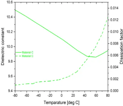
a patch antenna depends on geographical position, ambient temperature variation, especially under the influence of solar radiations [1], [2], [17]. In large-scale integrat-ed microwave applications, MSAs are thermally affectintegrat-ed, leading to undesirable vari-ations in their electrical properties. Fig. 1 and Fig. 2 [5] illustrates the behavioural characteristics of temperature variations to permittivity (dielectric constant) of its substrate material.
Fig. 1. Measured dielectric constant (εr) and dissipation factor (tan δ) for three categories (A,
B, D) of glass reinforced teflon laminates.
Fig. 2. Measured dielectric constant (εr) and dissipation factor (tan δ) for categories C of
ce-ramic filler laminate C.
its performance index on relationship between antenna resonant frequency shift and temperature variation with respect to the transmission line model [8]. According to [17], the dielectric constant of the patch’s substrate and the physical dimensions are temperature dependent, which affects the resonant frequencies of the microstrip patch antenna. Also, [17] evaluated the effect of temperature on the resonant frequencies of microstrip patch antennas in order to adopt a microstrip patch antenna as a tempera-ture sensor. It has been observed that the temperatempera-ture response of microstrip patch antennas leads to a simpler temperature sensor, inexpensive to produce and could be examined via wireless across a long distance. Hence [18], [19] have validated the strain sensing capability of microstrip patch antennas and temperature sensing capa-bilities enabling temperature compensated strain measurements resulting in a robust wireless antenna strain sensor at varying environmental conditions.
Most manufacturers typically emphasize on the frequency dependence of the mate-rial, neglecting the temperature drift when providing the thermal coefficient at the temperature range from 0oC (32 F) to 100oC (212 F) in the datasheets [5].
Microstrip patch antenna designers rely on the data provided in the manufacturer’s specifications, confined to standard environmental conditions. Practically, the electri-cal parameters of the substrates deviate with the temperature variation as illustrated in Fig. 1 and Fig. 2 [5], thus making the antenna designer adopt a deficient design strate-gy. The dielectric materials are categorized to Material A representing Ultralam 2000 and CuClad 250 LX laminates, while Material B represents RT/duroid 5880 and TLX-8 laminates. Material A and B include teflon-glass microwave laminates while C and D includes ceramic and quartz fiber composites respectively. The substrates are characterized by dielectric constants whose values decreased with temperature.
The rectangular configuration is the most common MSA because it’s easy to ana-lyze, fabricate and it has low cross-polarization characteristic. This study considered Transmission line model to provide better and accurate temperature relations to ana-lyze temperature effect on the performance parameters of the rectangular microstrip patch antenna (RMSA). Adapted equations are used to simulate three test RMSA substrate cases of different relative dielectric constant and thermal coefficient of die-lectric expansion. Behavioural characteristics of RMSA cases were investigated and observed under varying ambient temperatures.
2
RMSA Design Theory
2.1 Basic Design Theory
MSAs generally consist of a very thin (thickness, ) metallic strip or patch printed (photo-etched) on a small fraction of a wavelength ( , which represents the
height of the substrate material above a ground plane, .
The microstrip and the ground plane are separated by a dielectric surface, commonly called a substrate. The length of the rectangular patch is usual-ly . Different substrate materials have been employed for the design of the MSA, with their dielectric constant ( ) values ranging from range. Dielectric substrates for good antenna performance are thick materials with lower values since they have been found to provide better efficiency and larger bandwidth. Therefore, it’s essential for antenna design engineers to consid-er the choice of substrate vconsid-ery important. Although, thinnconsid-er dielectric substrates with higher are more desirable in microwave circuits because they lead to smaller ele-ment size and they have relatively smaller bandwidths. The design cost is reduced in efficiency, and greater losses are experienced. In practical applications, MSAs are mostly used in microwave applications. Hence, a compromise has to be reached to achieve good performance [3].
2.2 Transmission-Line Model
The RMSA physical characteristics can be illustrated as a combination of the sub-strate (Material A, B, C, D), height (h), patch (copper), width (w), length (l) and the ground (copper) plane. Hence, using the principles of a transmission line analysis, the RMSA can be represented by a low-impedance transmission line of length (L) [3], [7]. At a specified operating frequency ( , the following optimal design parameters of the RMSA can be approximated with the following equations, provided
,[3];
The effective dielectric constant ( ) is given by;
(1) The actual width (W) of the rectangular microstrip patch antenna;
(2) The actual length ( ) of the rectangular microstrip patch antenna;
p
(3) The extension in the length of the microstrip patch ) due to fringing;
(4) The effective length of the microstrip patch ( );
(5) Practically; as a result of coupling occurrence, the resonant input slot resistance ( ) when there is no feed point distance ) is expressed as [3];
(6)
(7)
(8)
(9) Where;
= Self-conductance, = Mutual-conductance,
= Phase constant of free-space (air),
= ,
= Bessel function of the first kind of order zero.
Assuming no coupling, the input slot resistance ( ) when there is no feed point distance is given as [3];
The rectangular patch antenna is matched to a coaxial microstrip line of 50 ohms input impedance. Hence, a feeding point distance from the radiating edge of the di-mension of the patch is introduced and expressed as;
(11)
(12) Therewith, the feeding point distance ( ) is derived from the edge of the mi-crostrip line in equation (8) and its given as;
(13)
3
Method of Analysis
Mostly, antenna temperature which is sometimes referred to as antenna noise tem-perature depends on the gain pattern and nature of the thermal environment its place to operate since it does not have an intrinsic temperature. The temperature of a patch antenna will vary depending on whether it’s directional, pointing into space or staring into the sun [7].
3.1 Temperature sensitivity
Generally, it has been accepted that the operating frequency of the MSA is sensi-tive to large temperature variations. Hence, most RMSA operations are concerned with how temperature drift affects the resonating frequency and the bandwidth of the RMSA [17]. Since the 1990s, the effect of temperature on MSA performance has been researched considering that most manufacturers of MSAs do not often account for temperature drift. Hence, careful selection of the electrical parameters of substrate materials (dielectric constant) least sensitive to temperature variation is a prerequisite to accomplishing a satisfactory MSA performance [5]. Manufacturers design patch antennas at room temperature using absolute temperatures or . Although, the ISO standard reference temperature for geometrical product specification and verification is .
(CTE). CTE does not change much over a varying temperature, except when the ma-terial’s temperature rises past its glass transition temperature ( ).
In choosing materials that are resistant to temperature variations for MSA, CTE ( ) of the substrate material and that of the metallic strip are very important. Therefore, with proper selection of the CTEs and dielectric constant, the effect of temperature drift can be made drastically negligible on the desired operating frequency. The CTDE of the substrate material is usually always higher than the CTE of the metallic strip, which is mainly copper. The expansion of the dielectric substrate material along its X and Y axes are negligible, only the expan-sion along the Z axes is considered. Hence, due to this thermal expanexpan-sion, there is a contraction or expansion in the length (L) of the metallic strip given as;
In MSAs, this expansion in length of the metallic strip has been found to induce a reduction in the resonating frequency [6] given as;
(14)
(15)
(16) Where;
= change in resonant frequency;
= change in effective resonant dimension; = thermal coefficient of expansion; = temperature change in .
In addition, contraction or expansion in electrical dimensions of dielectric substrate material is given as;
(17) The dielectric constant of most substrates used in microwave applications, tend to decrease with increase in temperature as presented in equation (18);
(18) The decrease in the MSAs effective dielectric constant of the substrate material relatively increases the resonating frequency, causing a reduction effect as a result of the expansion in the patch dimensions due to the rise in temperature.
By approximation of the relationship between and is given as [6];
g
(19) Where;
(20)
(21) = change in ;
= thermal coefficient of dielectric constant.
Combining equations (16) and (21) gives [6], [8];
(22)
3.2 Improved Temperature relations
The variations in the length, dielectric constant and operating frequency are ex-pressed in first-order differential equations (DEs). Therefore, to ascertain a general equation for the temperature variation in the MSAs, its required to integrate the equa-tions once. This can be achieved using either the separation-of-variables method or the direct integration method. Therewith, a boundary value (initial value) conditions are applied to obtain an optimum solution as illustrated in equation (23). The optimal solutions to the rectangular patch’s new dimensions, substrate’s dielectric constant and operating frequency of the MSA when subjected to thermal expansion or contrac-tion is given in equacontrac-tions (31), (34) and (36).
(23) will be the thermal coefficient of frequency expansion (CTFE).
(24)
(25)
(26)
Most MSAs are designed at room temperature ( ) to resonate at a particular oper-ating frequency ( ). The initial variables are expressed as;
(28)
(29)
(30)
(31) Hence, applying the integral and boundary conditions to the dielectric constant and operating frequency relationship using and , as initial variables gives;
(32)
(33)
(34)
(35)
(36) An optimal new rectangular patch antenna dimensions, substrate dielectric constant and operating frequency of the MSA, when subjected to thermal expansion or con-traction is obtained. These improved relations were programmed and simulated in MATLAB R2018a at harsh temperature variations. The obtained results agree with experimented conclusions in [6] and are shown and discussed in section 4.
4
Simulation of the RMSA
A parameter often describes in specification sheets for antennas that operate in cer-tain environments is the ratio of the antenna’s gain divided by the antenna’s tempera-ture, which is referred to as radiating near field or fresnel region of the source. It’s one of the important characteristics of an antenna explaining the spatial relative distribu-tion of the antenna’s power and electric field strength. This research work presents the temperature variation effect on the electric field plane, operating frequency (resonant
frequency) and the radiation pattern of a RMSA. The field radiation pattern of the RMSA was simulated usingMATLAB’S ANTENNA TOOLBOX functions.
4.1 Simulation algorithm
Theoretical design calculations of a RSMA [1] was adapted to analyze the antenna and the following procedures are deployed to simulate the effect of temperature varia-tion on a RMSA in MATLAB environment as illustrated below;
Step 1. Specify ambient temperature variation
• Specify the room temperature in degree celsius.
• Set the temperature range according to the geographical environment. • Smooth the temperature values for realistic simulation.
Step 2. Input analysis
• Input the following basic parameters of the required rectangular microstrip anten-na; substrate material, relative dielectric constant of substrate, thickness of the sub-strate, operating frequency, desired impedance of the feed line, and coefficients of thermal expansion of the metallic strip.
• Design the rectangular microstrip patch antenna to obtain other parameters; actual dimensions of the patch, effective permittivity, ground dimensions, input imped-ance, inset feed location along the length of the patch, notch width, gap of the feed line, bandwidth, directivity, quality factor, magnitude of the reflection coefficient, and voltage standing wave ratio.
Step 3. Calculate the design parameters as a function of Temperature Drift
• Shift the temperature index by making room temperature index the centre point, zero.
• Get the index of the specified room temperature, lowest temperature, and highest temperature from the temperature range.
• Calculate the patch antenna’s parameters due to temperature variation drift; length of patch, relative and effective permittivity of substrate, theoretical coefficient of thermal expansion of the operating frequency, resonant frequency, input imped-ance, new feed points from the radiating edge of the strip length, bandwidth, di-rectivity, reflection coefficient, voltage standing wave ratio.
Step 4: Analyse the rectangular patch antenna’s field patterns
• Create a realistic geometry for the patch antenna using the calculated parameters due to temperature variations.
4.2 Test cases
In this temperature variation analyses of a RMSA, copper has been used as the me-tallic patch material with a thickness of 0.035 mm, and the height (h) of the substrate material is 0.8 mm as applicable to miniaturized designs in communication applica-tions for the desired input impedance of 50 ohms.
The temperature sensitivity study of a RMSA was carried out on three different commercially available substrates namely; Rogers RT/Duroid 5870 [15],[20], Farnell FR-4 [16], [21], and Epsilam-10 [5]. The RMSA dimensions are in mm for each of the three tests at room temperature. The only variable in the test is the relative permit-tivity of the substrate material (A, B, C, D) and its coefficient of dielectric thermal expansion.
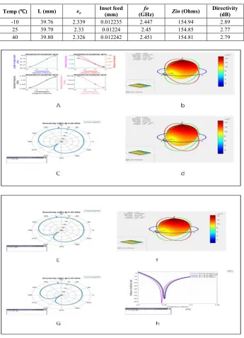
Case 1: Low ,
The Rogers RT/Duroid 5870 substrate was considered at 25 room temperature at the resonating frequency of 2.45 GHz. A comparative study of its operating frequency at -10oC and 40oC is carried out with the coefficient of thermal expansion (CTE) -115ppm/oC as illustrated in Table 1. and Fig. 3. illustrating the designed RMSA’s parameters varying with temperature. The variations are negligible on its operating frequency and other performance parameters due to its low .
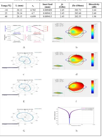
Case 2: Medium ,
A FR-4 substrate with the coefficient of thermal expansion (CTE) of 15ppm/oC is
considered at 25℃ room temperature. The comparative study of its operating frequen-cy at 2.45 GHz while varying the temperature from -10oC till 40 oC is illustrated in Table. 2 and Fig. 4. The designed RMSA’s parameters vary with temperature which is negligible on its operating frequency and other performance parameters. Comparing the temperature variation in case 1 and case 2, it’s observed that case 2 has better performance and resistance to temperature changes due to the combination of an aver-age closer to the lower range and low CTDE.
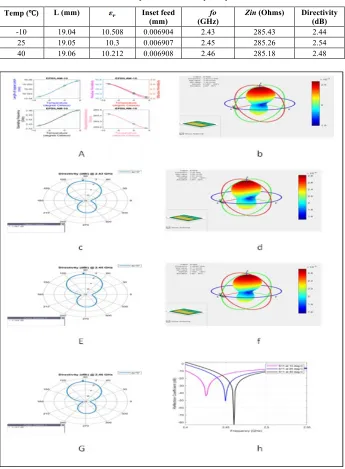
Case 3: High ,
Epsilam-10 substrate with the coefficient of thermal expansion (CTE) of 570ppm/oC is considered at 25 room temperature. A comparative study of its oper-ating frequency at 2.45 GHz varying at -10oC to 40oC is illustrated in Table. 3 and Fig. 5. The designed RMSA’s parameters varies relatively higher with temperature variation, affecting its resonant frequency (operating frequency) drastically.
It’s observed that Case 3 is an example of an unstable antenna compared to the other cases because it has a higher dielectric constant which is highly affected by high temperature variation as shown in Fig. 5(h). It deviates from the operating frequency more at lower temperatures than at higher temperatures. This effect can be reduced by selecting a material with high but lower CTDE. Comparing the three cases, it’s observed that the radiation pattern slightly varies at extreme temperature variations from the room temperature of operation. Looking at the directivity pattern characteris-tics of each substrate, the directive gains are relatively changed by a small amount due to extreme ambient temperatures.
r
Table 1. Results of temperature sensitivity study of Rogers RT5870
Temp (℃℃) L (mm) Inset feed (mm) (GHz) fo Zin (Ohms) Directivity (dB) -10 39.76 2.339 0.012235 2.447 154.94 2.89
25 39.79 2.33 0.01224 2.45 154.85 2.77 40 39.80 2.326 0.012242 2.451 154.81 2.79
Fig. 3. Rogers RT5870; temperature variation of the RMSA. (a) Patch length, relative permit-tivity, operating frequency and impedance. (b) Electric-field Pattern at -10oC. (c)
Di-rectivity at -10oC (d) Electric-field Pattern at 25oC. (e) Directivity at 25oC (f)
Electric-field Pattern at 40oC. (g) Directivity at 40oC. (h) Reflection coefficient variation at
Table 2. Results of temperature sensitivity study of FARNELL-FR4
Temp (℃℃) L (mm) Inset feed (mm) (GHz) fo Zin (Ohms) Directivity (dB) -10 28.12 4.702 0.009409 2.45 202.72 2.64
25 28.14 4.7 0.009413 2.45 202.60 2.60 40 28.15 4.699 0.009415 2.45 202.55 1.98
Fig. 4. FARNELL-FR4; temperature variation of the RMSA. (a) Patch length, relative permit-tivity, operating frequency and impedance. (b) Electric-field Pattern at -10oC. (c)
Di-rectivity at -10oC (d) Electric-field Pattern at 25oC. (e) Directivity at 25oC (f)
Electric-field Pattern at 40oC. (g) Directivity at 40oC. (h) Reflection coefficient variation at
Table 3. Results of temperature sensitivity study of EPSILAM-10
Temp (℃℃) L (mm) Inset feed
(mm) (GHz) fo Zin (Ohms) Directivity (dB) -10 19.04 10.508 0.006904 2.43 285.43 2.44
25 19.05 10.3 0.006907 2.45 285.26 2.54 40 19.06 10.212 0.006908 2.46 285.18 2.48
Fig. 5. EPSILAM-10; temperature variation of the RMSA. (a) Patch length, relative permittivi-ty, operating frequency and impedance. (b) Electric-field Pattern at -10oC. (c)
Directivi-ty at -10oC (d) Electric-field Pattern at 25oC. (e) Directivity at 25oC (f) Electric-field
Pattern at 40oC. (g) Directivity at 40oC. (h) Reflection coefficient variation at varying
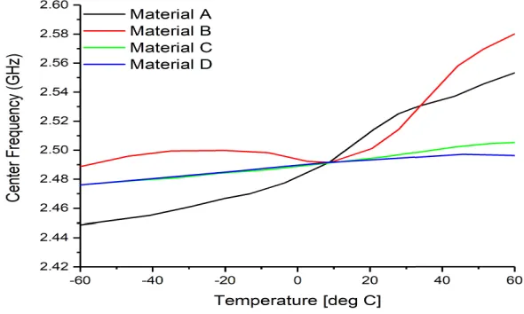
Fig. 6. Measurement result of comparison of Center frequency defined in terms of the mini-mum value of S11 versus temperature for antennas
The importance of evaluating the effect of thermal expansion in patch antenna de-sign is de-significant to antenna dede-sign engineers as illustrated in Fig. 3 – Fig. 6. The study shows apparent change in the physical dimensions of the antenna and a slight shift in the operating frequency as illustrated in Fig. 6. The materials A, B, C, D are categorized according to their material and dielectric constants. The simulated and measured results show the slight variation experienced in temperature variation in antenna.
5
Conclusion
6
Acknowledgement
The authors would like to acknowledge the support of Information Science Laborato-ry Center of USTC for software & hardware services, MediaTek for USTC students and project sponsorship, Micro/Nano-Electronic System Integration R&D Centre (MESIC), University of Science and Technology China; and Chinese Academy of Sciences and The World Academy of Sciences (CAS-TWAS) for their financial sup-port.
7
References
[1]Abatan, A. A., Abiodun, B. J., Lawal, K. A., Gutowski W. J. (2016). Trends in extreme temperature over Nigeria from percentile-based threshold indices. International Journal of Climatology, 36(6): 2527-2540. https://doi.org/10.1002/joc.4510
[2]Climates to Travel, https://www.climatestotravel.com/climate/nigeria Accessed 02 Febru-ary 2018.
[3]Balanis, C. A. (2005). Antenna Theory. Analysis and Design, 3rd ed., New York, Wiley. [4]Bird, T. S. (2009). Definition and Misuse of Return Loss. Antennas and Propagation
Ma-gazine, 51(2): 166-167. https://doi.org/10.1109/MAP.2009.5162049
[5]Kabacik, P., Bialkowski, M. E. (1999). The Temperature Dependence of Substrate Param-eters and Their Effect on Microstrip Antenna Performance. IEEE Transactions on Anten-nas and Propagation, 47(6): 1042-1049. https://doi.org/10.1109/8.777129
[6]Babu, S., Kumar, G. (1999). “Parametric Study and Temperature Sensitivity of Microstrip Antennas Using an Improved Linear Transmission Line Model,” IEEE Transactions on Antennas and Propagation, 47(2): 221-226. https://doi.org/10.1109/8.761060
[7]Milligan, T. A. (2005). Modern Antenna Design. Wiley-IEEE Press, 2nd Edition.
https://doi.org/10.1002/0471720615
[8]Yadav, R. K., Kishor, J., Yadava, R. L. (2013). Effects of temperature variations on mi-crostrip antenna. Int. J. Netw. Commun., 3(1): 21–24.
[9]Voytovich, N. I., Ershov, A. V., Bukharin, V. A., Repin, N. N. (2011). Temperature effect on cavity antenna parameters. General Assembly and Scientific Symposium, XXXth URSI, Istanbul, Turkey. https://doi.org/10.1109/URSIGASS.2011.6050422
[10]Weiss, M. A. (1981). Temperature compensation of microstrip antennas. IEEE Antennas Propagation Soc. Int. Symp. Dig., Los Angeles, CA, 1(1): 337–349.
https://doi.org/10.1109/APS.1981.1148532
[11]Ahamed, M. M. et al. (2012). Rectangular Microstrip Patch Antenna at 2GHZ on Differ-ent Dielectric constant for Pervasive Wireless Communication. International Journal of Electrical and Computer Engineering, 2(3): 417–424.
[12] Elrashidi, A., Elleithy, K., Bajwa, H. (2011). The performance of a cylindrical microstrip printed antenna for TM10 mode as a function of temperature for different substrates. In-ternational Journal of Next-Generation Networks, 3(3):1-18.
[13]Dubost, G. (1986). Linear transmission line model analysis of arbitrary shaped patch an-tennas. Electron. Lett., 22(15): 798–799. https://doi.org/10.1049/el:19860547
[15]Rogers Corporation (2018). https://www.rogerscorp.com/documents/606/acs/RT-duroid-5870-5880-DataSheet.pdf.
[16]Farnell (2018). https://www.farnell.com/datasheets/1644697.pdf.
[17] Sanders, J. W., Yao, J., Huang, H. (2015). Microstrip Patch Antenna Temperature Sensor, IEEE sensors journal, 15(9): 5312-5319. https://doi.org/10.1109/JSEN.2015.2437884
[18]Huang, H. (2013). Flexible wireless antenna sensor: A review. IEEE Sensors J., 13(10): 3865–3872. https://doi.org/10.1109/JSEN.2013.2242464
[19]Tata, U., Huang, H., Carter, R. L., Chiao, J. C. (2009). Exploiting a patch antenna for strain measurements. Meas. Sci. Technol., 20(1): 015201-015211.
https://doi.org/10.1088/0957-0233/20/1/015201
[20]Shaikh, S. A., Tekin, I. (2015). Two axis direction finding antenna system using sum– difference patterns in X band. Microwave Optical Technology Letters. 57(9): 2085–2092.
https://doi.org/10.1002/mop.29269
[21]Shaikh, S. A., Tonello, A. M. (2017). Performance Analysis of 1800 HRR Coupler Used
for Direction Finding with an Antenna Array. International Journal of Online Engineering (iJOE), 13(10): 86–102. https://doi.org/10.3991/ijoe.v13i10.7410
8
Authors
Akinwale O. Fadamiro (Corresponding Author) received his B. Eng. and M. Eng. in Electrical & Electronics Engineering, at the Federal University of Technology Akure, Nigeria. His currently studying his Ph.D. degree at the Department of Elec-tronic Science and Technology, University of Science and Technology of China (USTC), Hefei, China. His current research interest includes; antenna design, calibra-tion and optimizacalibra-tion.
Oluwole J. Famoriji received his B. Eng at the Ladoke Akintola University of Technology, Ogbomoso, Nigeria and M. Eng in Electrical & Electronics Engineering, at the Federal University of Technology Akure, Nigeria. Ph.D. degree at Department of Electronic Science and Technology, University of Science and Technology of Chi-na, Hefei, China. His research interests includes; Signal and Systems, Applied Elec-tromagnetics, and Microwave Engineering.
Rabiu S. Zakariyya received his B. Eng at the Kano University of Science and Technology, Wudil Kano, Nigeria and M. Eng in Electrical & Computer Engineering, at the Meliksah University Kayseri, Turkey. Currently studying his Ph.D. degree at the Department of Electronic Science and Technology, University of Science and Technology of China, Hefei, China.
Fujiang Lin received the B.S. and M.S. degrees in electrical engineering from the University of Science and Technology of China (USTC), Hefei, China, in 1982 and 1984, respectively, and the Dr.-Ing. degree in electrical engineering from the Univer-sity of Kassel, Kassel, Germany, in 1993. He joined the National UniverUniver-sity of Singa-pore, SingaSinga-pore, as a Research Scientist in 1993. In 2010, he joined the USTC as a Full Professor under the Chinese “1000 Talents Program”. He is the Executive Direc-tor of the MESIC, Hefei, China, “Micro-/Nano- Electronic System Integration Re-search and Development Center”.
Tech-nology Akure, Nigeria. His current research interests span development of control and computational intelligence algorithms.
Erastus O. Ogunti is an Associate Professor of Electrical, Electronics & Comput-er EngineComput-ering, at the FedComput-eral UnivComput-ersity of Technology Akure, NigComput-eria. His research interests are; electronics, micro-processor design, wireless sensor networks, MIMO OFDM, LTE networks.
Waliu O. Apena is a Senior Lecturer in Electrical, Electronics & Computer Engi-neering, at the Federal University of Technology Akure, Nigeria. His expertise in-cludes; Wireless Sensor Networks, Digital Communications, Biomedical Applica-tions, and Knowledge Based Engineering
Folasade. M. Dahunsi is a Senior Lecturer in Electrical, Electronics & Computer Engineering, at the Federal University of Technology Akure, Nigeria. Her research interest includes; Telecommunications, Networks and Services.