Computer Programming
Concepts and Visual Basic
David I. Schneider
U N I V E R S I T Y O F P H O E N I X
Excerpts taken from:
An Introduction to Programming Using Visual Basic 6.0, Fourth Edition, by David I. Schneider
Copyright © 1999, 1998, 1997, 1995 by Prentice-Hall, Inc. A Pearson Education Company
Upper Saddle River, New Jersey 07458
IBM is a registered trademark ® of International Business Machines Corporation Hercules is a registered trademark ® of Hercules Computer Technology.
Visual Basic is a registered trademark ® of the Microsoft Corporation.
The information, illustrations, and/or software contained in this book, and regarding the above-mentioned programs, are provided “As Is,” without warranty of any kind, express or implied, including without limitation any warranty concerning the accuracy, adequacy, or completeness of such information. Neither the publisher, the authors, nor the copyright holders shall be re-sponsible for any claims attributable to errors, omissions, or other inaccuracies contained in this book. Nor shall they be liable for direct, indirect, special, incidental, or consequential dam-ages arising out of the use of such information or material.
All rights reserved. No part of this book may be repro-duced, in any form or by any means, without permission in writing from the publisher.
This special edition published in cooperation with Pearson Custom Publishing
Printed in the United States of America
10 9 8 7 6 5 4 3 2 1
Please visit our web site at www.pearsoncustom.com
ISBN 0–536–60446–0
BA 990807
PEARSON CUSTOM PUBLISHING
C
ONTENTS
SECTION 1: PROBLEM SOLVING
. . . 11.1 PROGRAMDEVELOPMENTCYCLE . . . 3
1.2 PROGRAMMINGTOOLS . . . 5
SECTION 2: FUNDAMENTALS OF PROGRAMMING IN VISUAL BASIC
. . . 152.1 VISUALBASICOBJECTS . . . 17
2.2 VISUALBASICEVENTS . . . 27
2.3 NUMBERS . . . 34
2.4 STRINGS . . . 42
2.5 INPUT ANDOUTPUT . . . 49
2.6 BUILT-INFUNCTIONS . . . 58
SUMMARY . . . 67
PROGRAMMINGPROJECTS . . . 68
SECTION 3: GENERAL PROCEDURES
. . . 713.1 SUBPROCEDURES, PARTI . . . 73
3.2 SUBPROCEDURES, PARTII . . . 80
3.3 FUNCTIONPROCEDURES . . . 87
3.4 MODULARDESIGN . . . 93
SUMMARY . . . 97
PROGRAMMINGPROJECTS . . . 97
SECTION 4: DECISIONS
. . . 1014.1 RELATIONAL ANDLOGICALOPERATORS . . . 103
4.2 IFBLOCKS . . . 106
4.4 SELECTCASEBLOCKS . . . 112
4.4 A CASESTUDY: WEEKLY PAYROLL . . . 119
SUMMARY . . . 126
PROGRAMMINGPROJECTS . . . 126
SECTION 5: REPETITION
. . . 1295.1 DOLOOPS . . . 131
5.2 PROCESSINGLISTS OFDATA WITHDOLOOPS . . . 135
5.3 FOR...NEXTLOOPS . . . 141
5.4 A CASESTUDY: ANALYZE ALOAN . . . 146
SUMMARY . . . 153
PROGRAMMINGPROJECTS . . . 153
SECTION 6: ARRAYS
. . . 1596.1 CREATING ANDACCESSINGARRAYS . . . 161
6.2 USINGARRAYS . . . 171
6.3 CONTROLARRAYS . . . 179
6.4 SORTING ANDSEARCHING . . . 184
6.5 TWO-DIMENSIONALARRAYS . . . 196
6.6 A CASESTUDY: CALCULATING WITH ASPREADSHEET . . . 200
SECTION 7: SEQUENTIAL FILES
. . . 2157.1 SEQUENTIALFILES . . . 217
7.2 USINGSEQUENTIAL FILES . . . 223
7.3 A CASESTUDY: RECORDINGCHECKS ANDDEPOSITS . . . 228
SUMMARY . . . 237
PROGRAMMINGPROJECTS . . . 237
SECTION 8: RANDOM-ACCESS FILES
. . . 2438.1 USERDEFINEDDATATYPES . . . 245
8.2 RANDOM-ACCESSFILES . . . 251
SUMMARY . . . 255
PROGRAMMINGPROJECTS . . . 255
SECTION 9: THE GRAPHICAL DISPLAY OF DATA . . . 257
9.1 INTRODUCTION TOGRAPHICS . . . 259
9.2 LINECHARTS . . . 267
9.3 BARCHARTS . . . 273
9.4 PIECHARTS . . . 277
SUMMARY . . . 282
PROGRAMMINGPROJECTS . . . 282
SECTION 10: ADDITIONAL CONTROLS AND OBJECTS
. . . 28510.1 LISTBOXES ANDCOMBOBOXES . . . 287
10.2 NINEELEMENTARYCONTROLS . . . 294
10.3 FIVEADDITIONALOBJECTS . . . 303
SUMMARY . . . 316
PROGRAMMINGPROJECTS . . . 317
SECTION 11: DATABASE MANAGEMENT
. . . 32111.1 ANINTRODUCTION TODATABASES . . . 323
11.2 RELATIONALDATABASES AND SQL . . . 330
11.3 THREEADDITIONALDATA-BOUNDCONTROLS; CREATING ANDDESIGNINGDATABASES . . . . 338
SUMMARY . . . 350
PROGRAMMINGPROJECTS . . . 350
SECTION 12: OBJECT-ORIENTED PROGRAMMING . . . 353
12.1 CLASSES ANDOBJECTS . . . 355
12.2 COLLECTIONS ANDEVENTS . . . 365
12.3 CLASSRELATIONSHIPS . . . 373
SUMMARY . . . 380
PROGRAMMINGPROJECTS . . . 381
SECTION 13: COMMUNICATING WITH OTHER APPLICATIONS
. . . 38313.1 OLE . . . 385
13.2 ACCESSING THEINTERNET WITHVISUALBASIC . . . 392
APPENDICES
A. ANSI VALUES . . . 407 B. HOWTO . . . 409 C. VISUALBASICSTATEMENTS, FUNCTIONS, METHODS, PROPERTIES, EVENTS,
DATATYPES, ANDOPERATORS . . . 423 D. VISUALBASICDEBUGGINGTOOLS . . . 457
INDEX
. . . 465You have just purchased access to a valuable website that will open many doors
for you! The University of Phoenix has chosen to enhance and expand your
course’s material with a dynamic website that contains an abundance of rich and
valuable online resources specifically designed to help you achieve success!
This website provides you with material selected and added to powerful
online tools that have been seamlessly integrated with this textbook, resulting in
a dynamic, course-enhancing learning system. These exciting tools include:
Online Study Guide
Online glossary
Links to selected, high-quality websites
And more!
You can begin to access these tremendous resources immediately!
www.pearsoncustom.com/uop:
The opening screen of the University of
Phoenix website includes book covers of all the Pearson Custom Publishing
books in the BSBIS and BSIT programs. Click on the book cover representing
your course. This will launch the online study guide for the course in which you
are currently enrolled and the glossary of key terms for all the University of
Phoenix BSBIS and BSIT courses.
CD-ROM:
The accompanying CD-ROM includes key terms underlined
within the online book that are linked to the World Wide Web. Use the enclosed
CD-ROM to launch websites selected to reinforce your learning experience.
PROBLEM SOLVING
3
Hardware refers to the machinery in a computer system (such as the monitor, keyboard, and CPU) and software refers to a collection of instructions, called a program (or project), that directs the hardware. Programs are written to solve problems or perform tasks on a comput-er. Programmers translate the solutions or tasks into a language the computer can understand. As we write programs, we must keep in mind that the computer will only do what we instruct it to do. Because of this, we must be very careful and thorough with our instructions.
■
PERFORMING A
TASK ON THE
COMPUTER
The first step in writing instructions to carry out a task is to determine what the output should be—that is, exactly what the task should produce. The second step is to identify the data, or
input, necessary to obtain the output. The last step is to determine how to process the input
to obtain the desired output, that is, to determine what formulas or ways of doing things can be used to obtain the output.
This problem-solving approach is the same as that used to solve word problems in an algebra class. For example, consider the following algebra problem:
How fast is a car traveling if it goes 50 miles in 2 hours?
The first step is to determine the type of answer requested. The answer should be a num-ber giving the rate of speed in miles per hour (the output). The information needed to obtain the answer is the distance and time the car has traveled (the input). The formula
rate distance / time
is used to process the distance traveled and the time elapsed in order to determine the rate of speed. That is,
We determine what we want as output, get the needed input, and process the input to pro-duce the desired output.
In the following chapters we discuss how to write programs to carry out the preceding operations. But first we look at the general process of writing programs.
■
P
ROGRAMP
LANNINGA recipe provides a good example of a plan. The ingredients and the amounts are determined by what is to be baked. That is, the output determines the input and the processing. The recipe, or plan, reduces the number of mistakes you might make if you tried to bake with no plan at all. Although it’s difficult to imagine an architect building a bridge or a factory without a de-tailed plan, many programmers (particularly students in their first programming course) fre-quently try to write programs without first making a careful plan. The more complicated the problem, the more complex the plan must be. You will spend much less time working on a program if you devise a carefully thought out step-by-step plan and test it before actually writ-ing the program.
Many programmers plan their programs using a sequence of steps, referred to as the
pro-gram development cycle. The following step-by-step process will enable you to use your
time efficiently and help you design error-free programs that produce the desired output. 1. Analyze: Define the problem.
Be sure you understand what the program should do, that is, what the output should be. Have a clear idea of what data (or input) are given and the relation-ship between the input and the desired output.
2. Design: Plan the solution to the problem.
Find a logical sequence of precise steps that solve the problem. Such a sequence of steps is called an algorithm. Every detail, including obvious steps, should appear in the algorithm. In the next section, we discuss three popular methods used to develop the logic plan: flowcharts, pseudocode, and top-down charts. These tools help the programmer break a problem into a sequence of small tasks the computer can perform to solve the problem.
Planning also involves using representative data to test the logic of the algo-rithm by hand to ensure that it is correct.
3. Choose the interface: Select the objects (text boxes, command buttons, etc.). Determine how the input will be obtained and how the output will be displayed. Then create objects to receive the input and display the output. Also, create appropriate command buttons to allow the user to control the program. 4. Code: Translate the algorithm into a programming language.
Coding is the technical word for writing the program. During this stage, the
program is written in Visual Basic and entered into the computer. The pro-grammer uses the algorithm devised in Step 2 along with a knowledge of Visu-al Basic.
5. Test and debug: Locate and remove any errors in the program.
Testing is the process of finding errors in a program, and debugging is the
process of correcting errors that are found. (An error in a program is called a
bug.) As the program is typed, Visual Basic points out certain types of program
6. Complete the documentation: Organize all the material that describes the pro-gram.
Documentation is intended to allow another person, or the programmer at a later date, to understand the program. Internal documentation consists of state-ments in the program that are not executed, but point out the purposes of vari-ous parts of the program. Documentation might also consist of a detailed description of what the program does and how to use the program (for instance, what type of input is expected). For commercial programs, documentation includes an instruction manual. Other types of documentation are the flowchart, pseudocode, and top-down chart that were used to construct the program. Although documentation is listed as the last step in the program development cycle, it should take place as the program is being coded.
1.2 PROGRAMMING TOOLS
This section discusses some specific algorithms and develops three tools used to convert al-gorithms into computer programs: flowcharts, pseudocode, and hierarchy charts.
You use algorithms every day to make decisions and perform tasks. For instance, when-ever you mail a letter, you must decide how much postage to put on the envelope. One rule of thumb is to use one stamp for every five sheets of paper or fraction thereof. Suppose a friend asks you to determine the number of stamps to place on an envelope. The following algorithm will accomplish the task.
1. Request the number of sheets of paper; call it Sheets. (input)
2. Divide Sheets by 5. (processing)
3. Round the quotient up to the next highest whole number;
call it Stamps. (processing)
4. Reply with the number Stamps. (output)
The preceding algorithm takes the number of sheets (Sheets) as input, processes the data, and produces the number of stamps needed (Stamps) as output. We can test the algo-rithm for a letter with 16 sheets of paper.
1. Request the number of sheets of paper; Sheets = 16. 2. Dividing 5 into 16 gives 3.2.
3. Rounding 3.2 up to 4 gives Stamps = 4. 4. Reply with the answer, 4 stamps.
This problem-solving example can be pictured by
Of the program design tools available, the three most popular are the following:
Flowcharts: Graphically depict the logical steps to carry out a task and show how the steps
relate to each other.
Pseudocode: Uses English-like phrases with some Visual Basic terms to outline the task.
■
FLOWCHARTS
A flowchart consists of special geometric symbols connected by arrows. Within each symbol is a phrase presenting the activity at that step. The shape of the symbol indicates the type of operation that is to occur. For instance, the parallelogram denotes input or output. The arrows connecting the symbols, called flowlines, show the progression in which the steps take place. Flowcharts should “flow” from the top of the page to the bottom. Although the symbols used in flowcharts are standardized, no standards exist for the amount of detail required within each symbol.
A table of the flowchart symbols adopted by the American National Standards Institute (ANSI) follows. Figure 1-1 shows the flowchart for the postage stamp problem.
The main advantage of using a flowchart to plan a task is that it provides a pictorial rep-resentation of the task, which makes the logic easier to follow. We can clearly see every step and how each step is connected to the next. The major disadvantage with flowcharts is that when a program is very large, the flowcharts may continue for many pages, making them dif-ficult to follow and modify.
Symbol, Name, Meaning
Flowline Used to connect symbols and indicate the flow of logic.
Terminal Used to represent the beginning (Start) or the end (End) of a task.
Input/Output Used for input and output operations, such as read-ing and printread-ing. The data to be read or printed are described inside.
Processing Used for arithmetic and data-manipulation opera-tions. The instructions are listed inside the symbol.
Decision Used for any logic or comparison operations. Unlike the input/output and processing symbols, which have one entry and one exit flowline, the decision symbol has one entry and two exit paths. The path chosen depends on whether the answer to a ques-tion is “yes” or “no.”
Connector Used to join different flowlines.
Offpage Used to indicate that the flowchart continuesto a Connector second page.
Predefined Used to represent a group of statements that Process perform one processing task.
FIGURE 1-1 Flowchart for the Postage Stamp Problem
■
PSEUDOCODE
Pseudocode is an abbreviated version of actual computer code (hence, pseudocode). The geo-metric symbols used in flowcharts are replaced by English-like statements that outline the process. As a result, pseudocode looks more like computer code than does a flowchart. Pseudocode allows the programmer to focus on the steps required to solve a problem rather than on how to use the computer language. The programmer can describe the algorithm in Visual Basic-like form without being restricted by the rules of Visual Basic. When the pseudocode is completed, it can be easily translated into the Visual Basic language.
The following is pseudocode for the postage stamp problem:
Program: Determine the proper number of stamps for a letter
Read Sheets (input)
Set the number of stamps to Sheets / 5 (processing) Round the number of stamps up to the next whole number (processing)
Pseudocode has several advantages. It is compact and probably will not extend for many pages as flowcharts commonly do. Also, the plan looks like the code to be written and so is preferred by many programmers.
■
H
IERARCHYC
HARTThe last programming tool we’ll discuss is the hierarchy chart, which shows the overall pro-gram structure. Hierarchy charts are also called structure charts, HIPO (Hierarchy plus Input-Process-Output) charts, top-down charts, or VTOC (Visual Table of Contents) charts. All these names refer to planning diagrams that are similar to a company’s organization chart.
Hierarchy charts depict the organization of a program but omit the specific processing logic. They describe what each part, or module, of the program does and they show how the modules relate to each other. The details on how the modules work, however, are omitted. The chart is read from top to bottom and from left to right. Each module may be subdivided into a succession of submodules that branch out under it. Typically, after the activities in the succession of submodules are carried out, the module to the right of the original module is considered. A quick glance at the hierarchy chart reveals each task performed in the program and where it is performed. Figure 1-2 shows a hierarchy chart for the postage stamp prob-lem.
FIGURE 1-2 Hierarchy Chart for the Postage Stamp Problem
The main benefit of hierarchy charts is in the initial planning of a program. We break down the major parts of a program so we can see what must be done in general. From this point, we can then refine each module into more detailed plans using flowcharts or pseudocode. This process is called the divide-and-conquer method.
The postage stamp problem was solved by a series of instructions to read data, perform calculations, and display results. Each step was in a sequence; that is, we moved from one line to the next without skipping over any lines. This kind of structure is called a sequence
structure. Many problems, however, require a decision to determine whether a series of
FIGURE 1-3 Pseudocode and Flowchart for a Decision Structure
The sequence and decision structures are both used to solve the following problem.
■
DIRECTION OF
NUMBERED
NYC STREETS
ALGORITHM
Problem: Given a street number of a one-way street in New York, decide the direction of the
street, either eastbound or westbound.
Discussion: There is a simple rule to tell the direction of a one-way street in New York: Even
numbered streets run eastbound.
Input: Street number
Processing: Decide if the street number is divisible by 2.
Output: “Eastbound” or “Westbound”
Figures 1-4 through 1-6 show the flowchart, pseudocode, and hierarchy chart for the New York numbered streets problem.
Program: Determine the direction of a numbered NYC street.
Get Street
If Street is even Then Display Eastbound Else
Display Westbound End If
FIGURE 1-5 Pseudocode for the New York Numbered Streets Problem
FIGURE 1-6 Hierarchy Chart for the New York Numbered Streets Problem
The solution to the next problem requires the repetition of a series of instructions. A pro-gramming structure that executes instructions many times is called a loop structure.
We need a test (or decision) to tell when the loop should end. Without an exit condition, the loop would repeat endlessly (an infinite loop). One way to control the number of times a loop repeats (often referred to as the number of passes or iterations) is to check a condition before each pass through the loop and continue executing the loop as long as the condition is true. See Figure 1-7.
FIGURE 1-7 Pseudocode and Flowchart for a Loop
■
CLASS
A
VERAGEALGORITHM
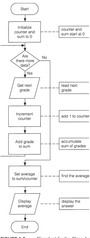
Problem: Calculate and report the grade-point average for a class.
Discussion: The average grade equals the sum of all grades divided by the number of
stu-dents. We need a loop to read and then add (accumulate) the grades for each student in the class. Inside the loop, we also need to total (count) the number of students in the class. See Figures 1-8 to 1-10.
Input: Student grades
Processing: Find the sum of the grades; count the number of students; calculate average grade
= sum of grades / number of students.
Output: Average grade
FIGURE 1-10 Hierarchy Chart for the Class-Average Problem
COMMENTS
1. Tracing a flowchart is like playing a board game. We begin at the Start symbol and proceed from symbol to symbol until we reach the End symbol. At any time, we will be at just one symbol. In a board game, the path taken depends on the result of spinning a spinner or rolling a pair of dice. The path taken through a flowchart depends on the input.
2. The algorithm should be tested at the flowchart stage before being coded into a program. Different data should be used as input, and the output checked. This process is known as desk checking. The test data should include nonstandard data as well as typical data.
3. Flowcharts, pseudocode, and hierarchy charts are universal problem-solving tools. They can be used to construct programs in any computer language, not just Visual Basic.
4. Flowcharts are used throughout this text to provide a visualization of the flow of certain programming tasks and Visual Basic control structures. Major exam-ples of pseudocode and hierarchy charts appear in the case studies.
5. There are four primary logical programming constructs: sequence, decision, loop, and unconditional branch. Unconditional branch, which appears in some languages as Goto statements, involves jumping from one place in a program to another. Structured programming uses the first three constructs but forbids the fourth. One advantage of pseudocode over flowcharts is that pseudocode has no provision for unconditional branching and thus forces the programmer to write structured programs.
6. Flowcharts are time-consuming to write and difficult to update. For this reason, professional programmers are more likely to favor pseudocode and hierarchy charts. Because flowcharts so clearly illustrate the logical flow of programming techniques, however, they are a valuable tool in the education of programmers. Program: Determine the average grade of a class
Initialize Counter and Sum to 0 Do While there are more data
Get the next Grade Add the Grade to the Sum Increment the Counter Loop Compute Average = Sum / Counter Display Average
7. There are many styles of pseudocode. Some programmers use an outline form, whereas others use a form that looks almost like a programming language. The pseudocode appearing in the case studies of this text focuses on the primary tasks to be performed by the program and leaves many of the routine details to be completed during the coding process. Several Visual Basic keywords, such as, Print, If, Do, and While, are used extensively in the pseudocode appearing in this text.
FUNDAMENTALS OF
PROGRAMMING IN VISUAL BASIC
17
Visual Basic programs display a Windows style screen (called a form) with boxes into which users type (and edit) information and buttons that they click to initiate actions. The boxes and buttons are referred to as controls. Forms and controls are called objects. In this section, we examine forms and four of the most useful Visual Basic controls.
Note: If Visual Basic has not been installed on your computer, you can install it by
fol-lowing the steps outlined on the first page of Appendix B.
Invoking Visual Basic 6.0: To invoke Visual Basic, click the Start button, point to
Pro-grams, point to Microsoft Visual Basic 6.0, and click on Microsoft Visual Basic 6.0 in the final list.
With all versions of Visual Basic 6.0, the center of the screen will contain the New Pro-ject window of Figure 2-1. The main part of the window is a tabbed dialog box with three tabs—New, Existing, and Recent. (If the New tab is not in the foreground, click on it to bring it to the front.) The number of project icons showing are either three (with the Working Model and Learning Editions) or thirteen (with the Professional and Enterprise Editions).
Double-click the Standard EXE icon to bring up the initial Visual Basic screen in Fig-ure 2-2. The appearance of this screen varies slightly with the different versions of Visual Basic.
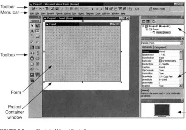
FIGURE 2-2 The Initial Visual Basic Screen
The Menu bar of the Visual Basic screen displays the commands you use to work with Visual Basic. Some of the menus, like File, Edit, View, and Window, are common to most Windows applications. Others, such as Project, Format, and Debug, provide commands spe-cific to programming in Visual Basic.
The Toolbar is a collection of icons that carry out standard operations when clicked. For example, the fifth icon, which looks like a diskette, can be used to save the current program to a disk. To reveal the function of a Toolbar icon, position the mouse pointer over the icon for a few seconds.
The large stippled Form window, or form for short, becomes a Windows window when a program is executed. Most information displayed by the program appears on the form. The information usually is displayed in controls that have been placed on the form. The Form
Layout window allows you to position the location of the form at run time relative to the
entire screen using a small graphical representation of the screen.
The Project Explorer window is seldom needed for our purposes until Section 12. The
Properties window is used to change how objects look and react.
The icons in the Toolbox represent controls that can be placed on the form. The four controls discussed in this section are text boxes, labels, command buttons, and picture boxes.
Text boxes: You use a text box primarily to get information, referred to as input, from the user.
Labels: You place a label to the left of a text box to tell the user what type of informa-tion to enter into the text box. You also use labels to display output.
Command buttons: The user clicks a command button to initiate an action.
A TEXT
BOX
W
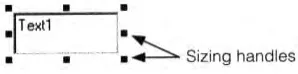
ALKTHROUGH1. Double-click on the text box icon. (The text box icon consists of the letters ab and a vertical bar cursor inside a rectangle and is the fourth icon in the Tool-box.) A rectangle with eight small squares, called sizing handles, appears at the center of the form. See Figure 2-3.
FIGURE 2-3 A Text Box with Sizing Handles
2. Click anywhere on the form outside the rectangle to remove the handles. 3. Click on the rectangle to restore the handles. An object showing its handles is
(said to be) selected. A selected object can have its size altered, location changed, and other properties modified.
4. Move the mouse arrow to the handle in the center of the right side of the text box. The cursor should change to a double arrow ( ). Hold down the left mouse button, and move the mouse to the right. The text box is stretched to the right. Similarly, grabbing the text box by one of the other handles and moving the mouse stretches the text box in another direction. For instance, you use the handle in the upper-left corner to stretch the text box up and to the left. Handles also can be used to make the text box smaller.
5. Move the mouse arrow to any point of the text box other than a handle, hold down the left mouse button, and move the mouse. You can now drag the text box to a new location. Using Steps 4 and 5, you can place a text box of any size any-where on the form.
Note: The text box should now be selected; that is, its sizing handles should be
showing. If not, click anywhere inside the text box to select it.
6. Press the delete key, Del, to remove the text box from the form. Step 7 gives an alternative way to place a text box of any size at any location on the form. 7. Click on the text box icon in the Toolbox. Then move the mouse pointer to any
place on the form. (When over the form, the mouse pointer becomes a pair of crossed thin lines.) Hold down the left mouse button, and move the mouse on a diagonal to generate a rectangle. Release the mouse button to obtain a selected text box. You can now alter the size and location as before.
Note: The text box should now be selected; that is, its sizing handles should be
showing. If not, click anywhere inside the text box to select it.
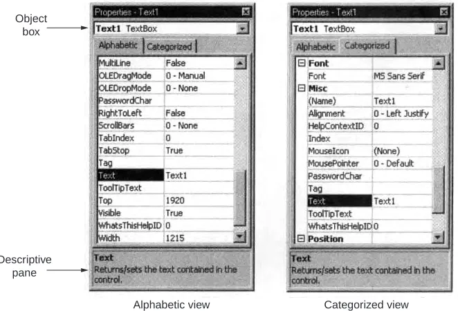
8. Press F4 to activate the Properties window. (You can also activate the properties window by clicking on it or clicking on the Properties window icon in the Tool-bar.) See Figure 2-4. The first line of the Properties window (called the Object
box) reads “Text1 TextBox”. Text1 is the current name of the text box. The two
FIGURE 2-4 Text Box Properties Window
9. Move to the Text property with the up- and down-arrow keys. (Alternatively, scroll until the property is visible and click on the property.) The Text property is now highlighted. The Text property determines the words in the text box. Cur-rently, the words are set to “Text1” in the Settings box on the right.
10. Type your first name. As you type, your name replaces “Text1” in both the Set-tings box and the text box. See Figure 2-5. (Alternatively, you could have clicked on the Settings box and edited its contents.)
FIGURE 2-5 Setting the Text Property to David
11. Click at the beginning of your name in the Settings box and add your title, such as Mr., Ms., or The Honorable. (If you mistyped your name, you can easily cor-rect it now.)
12. Press Shift+Ctrl+F to move to the first property that begins with the letter F. Now use the down-arrow key or the mouse to highlight the property ForeColor. The foreground color is the color of the text.
13. Click on the down arrow in the right part of the Settings box, and then click on the Palette tab to display a selection of colors. See Figure 2-6. Click on one of the solid colors, such as blue or red. Notice the change in the color of your name.
Categorized view Alphabetic view
Descriptive pane
FIGURE 2-6 Setting the ForeColor Property
14. Highlight the Font property with a single click of the mouse. The current font is named MS Sans Serif.
15. Click on the ellipsis (...) box in the right part of the settings box to display a dia-log box. See Figure 2-7. The three lists give the current name (MS Sans Serif), current style (Regular), and current size (8) of the font. You can change any of these attributes by clicking. Click on Bold in the style list,and click on 12 in the size list. Now click on the OK button to see your name displayed in a larger bold font.
16. Click on the text box and resize it to be about 3 inches wide and 1 inch high.
FIGURE 2-7 The Font Dialog Box
17. Press F5 to run the program. (Alternatively, a program can be run from the menu by pressing Alt/R/S or by clicking on the Start icon , the twelfth icon on the Toolbar.) Notice that the dots have disappeared from the form.
18. The cursor is at the beginning of your name. Press the End key to move the cur-sor to the end of your name. Now type in your last name, and then keep typing. Eventually, the words will scroll to the left.
19. Press Home to return to the beginning of the text. You have a full-fledged word processor at your disposal. You can place the cursor anywhere you like to add or delete text. You can drag the cursor across text to create a block, place a copy of the block in the clipboard with Ctrl+C, and then duplicate it anywhere with Ctrl+V.
20. To terminate the program, press Alt+F4. Alternatively, you can end a program by clicking on the End icon , the fourteenth icon on the Toolbar, or clicking on the form’s close button .
21. Select the text box, activate the Properties window, select the MultiLine prop-erty, click on the down-arrow button, and finally click on True. The MultiLine property has been changed from False to True.
22. Run the program, and type in the text box. Notice that now words wrap around when the end of a line is reached. Also, text will scroll up when it reaches the bottom of the text box.
23. End the program.
24. Press Alt/F/V, or click on the Save Project icon to save the work done so far. A Save File As dialog box appears. See Figure 2-8. Visual Basic creates two disk files to store a program. The first, with the extension .frm, is entered into the Save File As dialog box and the second, with the extension .vbp, into a Save Project As dialog box. Visual Basic refers to programs as projects.
FIGURE 2-8 The Save File As Dialog Box
26. Click the Save button when you are ready to go on. (Alternatively, press Tab several times until the Save button is highlighted and then press Enter.) The Save Project As dialog box appears.
27. Type a file name into the File name box. You can use the same name, such as testprog, as before. Then proceed as in Steps 25 and 26. (The extension .vbp will be added.)
28. Press Alt/F/N to begin a new program. (As before, select Standard EXE.) 29. Place three text boxes on the form. (Move each text box out of the center of the
form before creating the next.) Notice that they have the names Text1, Text2, and Text3.
30. Run the program. Notice that the cursor is in Text1. We say that Text1 has the
focus. (This means that Text1 is the currently selected object and any keyboard
actions will be sent directly to this object.) Any text typed will display in that text box.
31. Press Tab once. Now, Text2 has the focus. When you type, the characters appear in Text2.
32. Press Tab several times and then press Shift+Tab a few times. With Tab, the focus cycles through the objects on the form in the order the objects were cre-ated. With Shift+Tab, the focus cycles in the reverse order.
33. End the program.
34. Press Alt/F/O, or click on the Open Project icon to reload your first pro-gram. When a dialog box asks if you want to save your changes, click the No button or press N. An Open Project dialog box appears on the screen. Click on the Recent tab to see a list of the programs most recently opened or saved. Your first program and its location should appear at the top of the list. (Note: You can also find any program by clicking on the Existing tab and using the dialog box to search for the program.)
35. Click on the name of your first program and then click on the Open button. Alternatively, double-click on the name. (You also have the option of typing the name into the File Name box and then clicking the Open button.)
A C
OMMANDB
UTTONW
ALKTHROUGH1. Press Alt/F/N and double-click on Standard EXE to start a new program. There is no need to save anything.
2. Double-click on the command button icon to place a command button in the center of the form. (The rectangular-shaped command button icon is the sixth icon in the Toolbox.)
3. Activate the Properties window, highlight the Caption property, and type “Please Push Me”. See Figure 2-9. Notice that the letters appear on the com-mand button as they are typed. The button is too small.
4. Click on the command button to select it, and then enlarge it to accommodate the phrase “Please Push Me” on one line.
5. Run the program, and click on the command button. The command button appears to move in and then out. In Section 2.2, we write code that is activated when a command button is pushed.
6. End the program, and select the command button.
7. From the Properties window, edit the Caption setting by inserting an ampersand (&) before the first letter, P. Notice that the ampersand does not show on the button. However, the letter following the ampersand is now underlined. See Fig-ure 2-10. Pressing Alt+P while the program is running executes the same code as clicking the command button. Here, P is referred to as the access key for the command button. (The access key is always specified by the character follow-ing the ampersand.)
FIGURE 2-10 Designating P as an Access Key
A L
ABELW
ALKTHROUGH1. Press Alt/F/N and double-click on Standard EXE to start a new program. There is no need to save anything.
2. Double-click on the label icon to place a label in the center of the form. (The label icon, a large letter A, is the third icon in the Toolbox.)
3. Activate the Properties window, highlight the Caption property, and type “Enter Your Phone Number”. Such a label would be placed next to a text box into which the user will enter a phone number.
4. Click on the label to select it, and then widen it until all words are on the same line.
5. Make the label narrower until the words occupy two lines.
6. Activate the Properties window, and double-click on the Alignment property. Double-click two more times and observe the label’s appearance. The combina-tion of sizing and alignment permits you to design a label easily.
7. Run the program. Nothing happens, even if you click on the label. Labels just sit there. The user cannot change what a label displays unless you write code to allow the change.
8. End the program.
A P
ICTUREB
OXW
ALKTHROUGH2. Double-click on the picture box icon to place a picture box in the center of the form. (The picture box icon is the second icon in the Toolbox. It contains a pic-ture of the sun shining over a desert.)
3. Enlarge the picture box.
4. Run the program. Nothing happens and nothing will, no matter what you do. Although picture boxes look like text boxes, you can’t type in them. However, you can display text in them with statements discussed later in this section, you can draw lines and circles in them with statements discussed in Section 9, and you can insert pictures into them.
5. End the program and click the picture box to select it.
6. Activate the Properties window, and double-click on the Picture property. A Load Picture dialog box appears. See Figure 2-11.
FIGURE 2-11 The Load Picture Dialog Box
7. Select the Windows folder and then double-click on one of the picture files. Good candidates are Clouds.bmp, shown in Figure 2-12, and Setup.bmp. (Also, the CD accompanying this textbook contains several picture files in the folder Pictures.)
FIGURE 2-12 A Picture Box Filled with the Clouds.bmp Picture
COMMENTS
1. When selecting from a list, double-clicking has the same effect as clicking once and pressing Enter.
2. On a form, the Tab key cycles through the objects that can get the focus, and in a dialog box, it cycles through the items.
3. The form itself is also an object and has properties. For instance, you can change the text in the title bar with the Caption property. You can move the form by dragging the title bar of its Project Container window.
4. The name of an object is used in code to refer to the object. By default, objects are given names like Text1 and Text2. You can use the Properties window to change the Name property of an object to a more suggestive name. (The Name property is always the first property in the list of properties. An object’s Name must start with a letter and can be a maximum of 40 characters. It can include numbers and underline (_) characters, but can’t include punctuation or spaces.) Also, Microsoft recommends that each name begin with a three-letter prefix that identifies the type of the control. See the table below. Beginning with Sec-tion 2.2, we will use suggestive names and these prefixes whenever possible.
Object Prefix Example
command button cmd cmdComputeTotal
form frm frmPayroll
label lbl blInstructions
picture box pic picClouds
text box txt txtAddress
5. The Name and Caption properties of a command button are both initially set to something like Command1. However, changing one of these properties does not affect the setting of the other property. Similarly for the Name and Caption properties of forms and labels, and for the Name and Text properties of text boxes.
6. The color settings appear as strings of digits and letters preceded by &H and trailed with &. Don’t concern yourself with the notation.
7. Here are some fine points on the use of the Properties window.
(a) Press Shift+Ctrl+letterkey to highlight the first property that begins with that letter. Successive pressings highlight successive properties that begin with that letter.
(b) To change the selected object from the Properties window, click on the down-arrow icon at the right of the Object box of the Properties window. Then select the new object from the drop-down list.
8. Some useful properties that have not been discussed are the following: (a) BorderStyle: Setting the BorderStyle to “0 – None” removes the border
from an object.
(b) Visible: Setting the Visible property to False hides an object when the pro-gram is run. The object can be made to reappear with code.
(c) BackColor: Specifies the background color for a text box, label, picture box, or form. Also specifies the background color for a command button having the Style property set to “1 – Graphical.” (Such a command button can display a picture.)
back-ground color and caption. Setting the backback-ground style of a label to trans-parent causes whatever is behind the label to remain visible; the back-ground color of the label essentially becomes “see through.”
(e) Font: Can be set to any of Windows’ fonts, such as Courier and Times New Roman. Two unusual fonts are Symbol and Wingdings. For instance, with the Wingdings font, pressing the keys for %, &, ‘, and J yield a bell, a book, a candle, and a smiling face, respectively. To view the character sets for the different Windows’ fonts, click on the Start button, and successively select Programs, Accessories, and Character Map. Then click on Character Map or press the Enter key. After selecting a font, hold down the left mouse but-ton on any character to enlarge it and obtain the keystroke that produces that character.
9. When you click on a property in the Properties window, a description of the property appears just below the window. Additional information about many of the properties can be found in Appendix C. With the Learning, Professional, and Enterprise Editions of VB6.0 you can obtain very detailed (and somewhat advanced) information about a property by clicking on the property and press-ing F1 for Help.
10. Most properties can be set or altered with code as the program is running instead of being preset from the Properties window. For instance, a command button can be made to disappear with a line such as Command1.Visible = False. See Section 2.2 for details.
11. The BorderStyle and MultiLine properties of a text box can be set only from the Properties window. You cannot alter them during run time.
12. Of the objects discussed in this section, only command buttons have true access keys.
13. If you inadvertently double-click an object in a form, a window containing two lines of text will appear. (The first line begins Private Sub.) This is a code win-dow and is discussed in the next section. To remove this winwin-dow, click on its Close button.
14. To enlarge (or decrease) the Project Container window, position the mouse cur-sor anywhere on the right or bottom edge and drag the mouse. To enlarge (or decrease) the form, select the form and drag one of its sizing handles. Alterna-tively, you can enlarge either the Project Container window or the form by clicking on its Maximize button.
15. We will always be selecting the Standard EXE icon from the New Project win-dow.
2.2 VISUAL BASIC EVENTS
When a Visual Basic program is run, a form and its controls appear on the screen. Normally, nothing happens until the user takes an action, such as clicking a control or pressing the Tab key. Such an action is called an event.
The three steps to creating a Visual Basic program are as follows: 1. Create the interface; that is, generate, position, and size the objects. 2. Set properties; that is, set relevant properties for the objects. 3. Write the code that executes when the events occur.
Code consists of statements that carry out tasks. Visual Basic has a repertoire of over 200 statements and we will use many of them in this text. In this section, we limit ourselves to statements that change properties of objects while a program is running.
Properties of an object are changed in code with statements of the form
objectName.property = setting
where objectName is the name of the form or a control, property is one of the properties of the object, and setting is a valid setting for that object. Such statements are called assignment
statements. They assign values to properties. Here are three other assignment statements.
The statement
txtBox.Font.Size = 12
sets the size of the characters in the text box named txtBox to 12. The statement
txtBox.Font.Bold = True
converts the characters in the text box to boldface. The statement
txtBox.Text = “”
clears the contents of the text box; that is, it invokes the blank setting.
Most events are associated with objects. The event clicking cmdButton is different from the event clicking picBox. These two events are specified cmdButton_Click and picBox_Click. The statements to be executed when an event occurs are written in a block of code called an event procedure. The structure of an event procedure is
Private Sub objectName_event()
statements
End Sub
The word Sub in the first line signals the beginning of the event procedure, and the first line identifies the object and the event occurring to that object. The last line signals the termina-tion of the event procedure. The statements to be executed appear between these two lines. (Note: The word Private indicates that the event procedure cannot be invoked by an event from another form. This will not concern us until much later in the text. The word Sub is an abbre-viation of Subprogram.) For instance, the event procedure
Private Sub cmdButton_Click() txtBox.Text = “”
End Sub
clears the contents of the text box when the command button is clicked.
■
A
NE
VENTP
ROCEDUREW
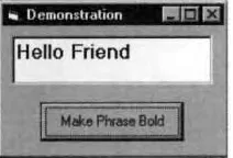
ALKTHROUGHThe form in Figure 2-13, which contains a text box and a command button, will be used to demonstrate what event procedures are and how they are created. Three event procedures will be used to alter the appearance of a phrase that is typed into the text box. The event procedures are txtPhrase_LostFocus, txtPhrase_GotFocus, and cmdBold_Click.
Object Property Setting
frmWalkthrough Caption Demonstration
txtPhrase Text (blank)
cmdBold Caption Make Phrase Bold
1. Create the interface in Figure 2-13. The Name properties of the form, text box, and command button should be set as shown in the Object column. The Caption property of the form should be set to Demonstration, the Text property of the text box should be made blank, and the Caption property of the command but-ton should be set to Make Phrase Bold.
2. Double-click on the text box. A window, called the Code window, appears. See Figure 2-14. Just below the title bar are two drop-down list boxes. The left box is called the Object box and the right box is called the Procedure box. (When you position the mouse pointer over one of these list boxes, its type appears.)
FIGURE 2-14 A Code Window
3. Click on the down-arrow button to the right of the Procedure box. The drop-down menu that appears contains a list of all possible event procedures associ-ated with text boxes. See Figure 2-15.
FIGURE 2-15 Drop-Down Menu of Event Procedures
4. Scroll down the list of event procedures and click on LostFocus. (LostFocus is the 14th event procedure.) The lines
Private Sub txtPhrase_LostFocus()
End Sub
appear in the code window with a blinking cursor poised at the beginning of the blank line.
Object box
5. Type the line
txtPhrase.Font.Size = 12
between the existing two lines. (We usually indent lines inside procedures.) (After you type each period, the editor displays a list containing possible choic-es of items to follow the period. See Figure 2-16. This feature is called “List Properties/Methods.” In Figure 2-16, instead of typing the word “Size,” you can double-click on “Size” in the displayed list or highlight the word “Size” and press Tab.) The screen appears as in Figure 2-17. We have now created an event procedure that is activated whenever the text box loses the focus.
FIGURE 2-16 A LostFocus Event Procedure
FIGURE 2-17 A LostFocus Event Procedure
6. Let’s create another event procedure for the text box. Click on the down-arrow button to the right of the Procedure box, scroll up the list of event procedures, and click on GotFocus. Then type the lines
txtPhrase.Font.Size = 8txtPhrase.Font.Bold = False
FIGURE 2-18 A GotFocus Event Procedure
7. The txtPhrase_Change event procedure in Figure 2-18 was not used and can be deleted. To delete the procedure, highlight it by dragging the mouse across the two lines of code, and then press the Del key.
8. Let’s now create an event procedure for the command button. Click on the down-arrow button to the right of the Object box. The drop-down menu con-tains a list of the objects, along with a mysterious object called (General). See Figure 2-19. [We’ll discuss (General) in the next section.]
FIGURE 2-19 List of Objects
9. Click on cmdBold. The event procedure cmdBold_Click is displayed. Type in the line
txtPhrase.Font.Bold = True
FIGURE 2-20 The Three Event Procedures
10. Now run the program by pressing F5.
11. Type something into the text box. In Figure 2-21, the words “Hello Friend” have been typed. (A text box has the focus whenever it is ready to accept typing; that is, whenever it contains a blinking cursor.)
FIGURE 2-21 Text Box Containing Input
12. Press the Tab key. The contents of the text box will be enlarged as in Figure 2-22. When Tab was pressed, the text box lost the focus; that is, the event Lost-Focus happened to txtPhrase. Thus, the event procedure txtPhrase_ LostLost-Focus was called, and the code inside the procedure was executed.
FIGURE 2-22 Text Box After It Has Lost the Focus
13. Click on the command button. This calls the event procedure cmd Bold_Click, which converts the text to boldface. See Figure 2-23.
14. Click on the text box or press the Tab key to move the cursor (and, therefore, the focus) to the text box. This calls the event procedure txtPhrase_GotFocus, which restores the text to its original state.
15. You can repeat Steps 11 through 14 as many times as you like. When you are finished, end the program by pressing Alt+F4, clicking the End icon on the Toolbar, or clicking the Close button (X) on the form.
COMMENTS
1. To hide the code window, press the right mouse button and click on Hide. You can also hide it by clicking on the icon at the left side of the title bar and click-ing on Close. To view a hidden code window, press Alt/View/Code. To hide a form, close its container. To view a hidden form, press Alt/View/Object. 2. The form is the default object in Visual Basic code. That is, code such as
Form1.property = setting
can be written as
property = setting
Also, event procedures associated with Form1 appear as
Form_event()
rather than
Form1_event()
3. Another useful command is SetFocus. The statement
object.SetFocus
moves the focus to the object.
4. We have ended our programs by clicking the End icon or pressing Alt+F4. A more elegant technique is to create a command button, call it cmdQuit, with caption Quit and the event procedure:
Private Sub cmdQuit_Click() End
End Sub
5. Certain words, such as Sub, End, and False, have special meanings in Visual Basic and are referred to as keywords or reserved words. The Visual Basic edi-tor automatically capitalizes the first letter of a keyword and displays the word in blue.
6. Visual Basic can detect certain types of errors. For instance, consider the line
txtPhrase.Font.Bold = False
button. After you click on Debug, the line containing the offending word will be highlighted.
7. At design time, colors are selected from a palette. At run time, the eight most common colors can be assigned with the color constants vbBlack, vbRed, vbGreen, vbYellow, vbBlue, vbMagenta, vbCyan, and vbWhite. For instance, the statement
picBox.BackColor = vbYellow
gives picBox a yellow background.
8. For statements of the form object.property = setting, with properties Caption, Text, or Font.Name, the setting must be surrounded by quotes. (For instance, lblTwo.Caption = “Name”, txtBox.Text = “Fore”, and picBox.Font.Name = “Courier”.) When the words True or False appear to the right of the equal sign, they should not be surrounded by quotation marks.
9. Code windows have many features of word processors. For instance, the opera-tions cut, copy, paste, find, undo, and redo can be carried out with the sixth through eleventh icons of the Toolbar. These operations, and several others, also can be initiated from the Edit menu.
10. Names of existing event procedures associated with an object are not automat-ically changed when you rename the object. You must change them yourself and also must change any references to the object. Therefore, you should finalize the names of your objects before you put any code into their event procedures. 11. If you find the automatic List Properties/Methods feature distracting, you can turn it off by pressing Tools/Options, selecting the Editor page, and clicking on Auto List Members. If you do so, you can still display a list manually at the appropriate time by pressing Ctrl+J.
12. Earlier versions of Visual Basic used the property FontSize instead of Font.Size. Although Font.Size is preferred, FontSize is allowed for compatibil-ity. Similarly, properties such as FontBold, FontItalic, and FontName have been included for compatibility with earlier versions of Visual Basic.
13. Assignment statements can be written preceded with the keyword Let. For instance,txtBox.Text = “Hello” also can be written Let txtBox.Text = “Hello”. Therefore, assignment statements are also known as Let statements.
2.3 NUMBERS
■
ARITHMETIC
OPERATIONS
The five arithmetic operations in Visual Basic are addition, subtraction, multiplication, divi-sion, and exponentiation. (Because exponentiation is not as familiar as the others, it is re-viewed in detail in Comment 10.) Addition, subtraction, and division are denoted in Visual Basic by the standard symbols +, –, and /, respectively. However, the notations for multipli-cation and exponentiation differ from the customary mathematical notations.
Mathematical Notation Visual Basic Notation
a b or ab a * b
ar a ^ r
(The asterisk [*] is the upper character of the 8 key. The caret [^] is the upper character of the 6 key.) Note: In this book, the proportional font used for text differs from the monospaced font used for programs. In the program font, the asterisk appears as a five-pointed star (*).
One way to show a number on the screen is to display it in a picture box. If n is a num-ber, then the instruction
picBox.Print n
displays the number n in the picture box. If the picBox.Print instruction is followed by a com-bination of numbers and arithmetic operations, it carries out the operations and displays the result. Print is a reserved word and the Print operation is called a method. Another important method is Cls. The statement
picBox.Cls
erases all text and graphics from the picture box picBox. EXAMPLE 1
The following program applies each of the five arithmetic operations to the numbers 3 and 2. Notice that 3/2 is displayed in decimal form. Visual Basic never displays numbers as common fractions. Note 1:The star in the fifth and eighth lines is the computer font version of the asterisk. Note 2:The word “Run” in the phrasing [Run ...] indicates that F5 should be pressed to execute the program. Note 3:All programs appearing in examples and case studies are provided on the CD accompanying this book. See the discus-sion on the next to last page of the book for details.
Below is the form design and a table showing the names of the objects on the form and the settings, if any, for properties of these objects. This form design is also used in the discussion and examples in the remainder of this section.
Object Property Setting
frm3_3_1 Caption, 3-3-1
picResults
cmdCompute Caption Compute
Private Sub cmdCompute_Click() picResults.Cls
picResults.Print 3 + 2 picResults.Print 3 - 2 picResults.Print 3 * 2 picResults.Print 3 / 2 picResults.Print 3 ^ 2 picResults.Print 2 * (3 + 4) End Sub
■
S
CIENTIFICN
OTATIONLet us review powers of 10 and scientific notation. Our method of decimal notation is based on a systematic use of exponents.
101 = 10 10–1= 1/10 = .1
102 = 100 10–2= .01
103 = 1000 10–3= .001
. . .
10n = 1000...0 10–n= .001...01
n zeros n digits
Scientific notation provides a convenient way of writing numbers by using powers of 10 to stand for zeros. Numbers are written in the form b10r, where b is a number from 1 up
to (but not including) 10, and r is an integer. For example, it is much more convenient to write the diameter of the sun (1,400,000,000 meters) in scientific notation: 1.4 109 meters.
Similarly, rather than write .0000003 meters for the diameter of a bacterium, it is simpler to write 3 10–7 meters.
Any acceptable number can be entered into the computer in either standard or scientific notation. The form in which Visual Basic displays a number depends on many factors, with size being an important consideration. In Visual Basic, b10ris usually written as bEr. (The
letter E is an abbreviation for exponent.) The following forms of the numbers just mentioned are equivalent.
1.4 * 10^9 1.4E+09 1 4E+9 1.4E9 1400000000
3 * 10^–7 3E–07 3E–7 .0000003
The computer displays r as a two-digit number, preceded by a plus sign if r is positive and a minus sign if r is negative.
EXAMPLE 2
The following program illustrates scientific notation. The computer’s choice of whether to display a num-ber in scientific or standard form depends on the magnitude of the numnum-ber.
Private Sub cmdCompute_Click() picResults.Cls
picResults.Print 1.2 * 10 ^ 34
picResults.Print 1.2 * 10 ^ 8 picResults.Print 1.2 * 10 ^ 3
picResults.Print 10 ^ -20
picResults.Print 10 ^ -2
End Sub
■
V
ARIABLESIn applied mathematics problems, quantities are referred to by names. For instance, consider the following high school algebra problem. “If a car travels at 50 miles per hour, how far will it travel in 14 hours? Also, how many hours are required to travel 410 miles?” The solution to this problem uses the well-known formula
distance = speed ×time elapsed Here’s how this problem would be solved with a computer program.
Private Sub cmdCompute_Click() picResults.Cls speed = 50 timeElapsed = 14
distance = speed * timeElapsed picResults.Print distance distance = 410
timeElapsed = distance / speed picResults.Print timeElapsed End Sub
[Run, and then click the command button. The following is displayed in the picture box.]
700 8.2
The third line of the event procedure sets the speed to 50, and the fourth line sets the time elapsed to 14. The fifth line multiplies the value for the speed by the value for the time elapsed and sets the distance to this product. The next line displays the answer to the first question. The three lines before the End Sub statement answer the second question in a similar manner.
The names speed, timeElapsed, and distance, which hold numbers, are referred to as
variables. Consider the variable timeElapsed. In the fourth line, its value was set to 14. In
the eighth line, its value was changed as the result of a computation. On the other hand, the variable speed had the same value, 50, throughout the program.
In general, a variable is a name that is used to refer to an item of data. The value assigned to the variable may change during the execution of the program. In Visual Basic, variable names can be up to 255 characters long, must begin with a letter, and can consist only of let-ters, digits, and underscores. (The shortest variable names consist of a single letter.) Visual Basic does not distinguish between uppercase and lowercase letters used in variable names. Some examples of variable names are total, numberOfCars, taxRate_1999, and n. As a con-vention, we write variable names in lowercase letters except for the first letters of addition-al words (as in numberOfCars).
If var is a variable and num is a constant, then the statement
var = num
assigns the number num to the variable var. (Such a statement is called an assignment
state-ment.) Actually, the computer sets aside a location in memory with the name var and places
the number num in it. The statement
looks into this memory location for the value of the variable and displays the value in the pic-ture box.
A combination of constants, variables, and arithmetic operations that can be evaluated to yield a number is called a numeric expression. Expressions are evaluated by replacing each variable by its value and carrying out the arithmetic. Some examples of expressions are 2 * distance + 7, n + 1, and (a + b) / 3.
EXAMPLE 3
The following program displays the value of an expression.
Private Sub cmdCompute_Click()
picResults.Cls
a = 5
b = 4
picResults.Print a * (2 + b)
End Sub
[Run, and then click the command button. The following is displayed in the picture box.]
30
If var is a variable, then the statement
var = expression
first evaluates the expression on the right and then assigns its value to the variable. For instance, the event procedure in Example 3 can be written as
Private Sub cmdCompute_Click()
picResults.Cls
a = 5
b = 4
c = a * (2 + b)
picResults.Print c
End Sub
The expression a * (2 + b) is evaluated to 30 and then this value is assigned to the variable c. Because the expression on the right side of an assignment statement is evaluated before an assignment is made, a statement such as
n = n + 1
is meaningful. It first evaluates the expression on the right (that is, it adds 1 to the orig-inal value of the variable n), and then assigns this sum to the variable n. The effect is to increase the value of the variable n by 1. In terms of memory locations, the statement retrieves the value of n from n’s memory location, uses it to compute n + 1, and then places the sum back into n’s memory location.
■
P
RINTM
ETHODConsider the following event procedure.
Private Sub cmdDisplay_Click()
picResults.Cls
picResults.Print 3
picResults.Print -3
End Sub
Notice that the negative number –3 begins directly at the left margin, whereas the positive number 3 begins one space to the right. The Print method always displays nonnegative num-bers with a leading space. The Print method also displays a trailing space after every number. Although the trailing spaces are not apparent here, we will soon see evidence of their presence.
The Print methods used so far display only one number per line. After displaying a num-ber, the cursor moves to the leftmost position and down a line for the next display. Borrow-ing from typewriter terminology, we say that the computer performs a carriage return and a line feed after each number is displayed. The carriage return and line feed, however, can be suppressed by placing a semicolon at the end of the number.
EXAMPLE 4
The following program illustrates the use of semicolons in Print methods. The output reveals the presence of the space trailing each number. For instance, the space trailing –3 combines with the leading space of 99 to produce two spaces between the numbers.
Private Sub cmdDisplay_Click() picResults.Cls
picResults.Print 3; picResults.Print -3; picResults.Print 99; picResults.Print 100 End Sub
[Run, and then click the command button.]
Semicolons can be used to display several numbers with one Print method. If m, n, and r are numbers, a line of the form
picBox.Print m; n; r
displays the three numbers, one after another, separated only by their leading and trail-ing spaces. For instance, the Print methods in precedtrail-ing Example 4 can be replaced by the single line
COMMENTS
1. Numbers must not contain commas, dollar signs, or percent signs. Also, mixed numbers, such as 8 1/2, are not allowed.
2. Some people think of the equal sign (=) in an assignment statement as an arrow pointing to the left. This stresses the fact that the value on the right is assigned to the variable on the left.
3. Parentheses should be used when necessary to clarify the meaning of an expres-sion. When there are no parentheses, the arithmetic operations are performed in the following order: (1) exponentiations; (2) multiplications and divisions; (3) additions and subtractions. In the event of ties, the leftmost operation is car-ried out first. Table 2-1 summarizes these rules.
TABLE 2-1
Level of Precedence for Arithmetic Operations
( ) Inner to outer, left to right ^ Left to right in expression */ Left to right in expression + – Left to right in expression
4. Restricted keywords cannot be used as names of variables. For instance, the statements print = 99 and end = 99 are not valid. Some other common restrict-ed keywords are Call, If, Let, Select, and Sub. If a keyword is usrestrict-ed as a variable name, you will soon be warned that something is wrong. As soon as the cursor is moved from the line, an error message will appear, and the line will turn red. The use of some other keywords (such as Error, Height, Name, Rate, Time, Val, Width, and Year) as variable names does not trigger an immediate warning, but generates an error message when the program is run. Although there is a way to get Visual Basic to accept this last group of keywords as variable names, we will never use keywords as variable names. Most of the items in Appendix C, other than properties, are reserved words. You can tell immediately when you inadvertently use a reserved word as a variable in an assignment statement because Visual Basic automatically capitalizes the first letter of keywords. For instance, if you type “rate = 50” and press the Enter key, the line will change to “Rate = 50”.
5. Grammatical errors, such as misspellings or incorrect punctuations, are called
syntax errors. Certain types of syntax errors are spotted by the smart editor
when they are entered, whereas others are not detected until the program is exe-cuted. When Visual Basic spots an error, it displays a dialog box. Some incor-rect statements and their errors are given below.
Statement Reason for Error
picBox.Primt 3 Misspelling of keyword
picBox.Print 2 + No number follows the plus sign 9W = 5 9W is not a valid variable name
6. Errors detected while a program is running are called run-time errors. Although some run-time errors are due to improper syntax, others result from the inability of the computer to carry out the intended task. For instance, if the value of numVar is 0, then the statement
numVarInv = 1/numVar
to the file by the filespec “C:\DATA.TXT” produces the run-time error “File not found.”
The dialog box generated by a run-time error states the type of error and has a row of four command buttons captioned Continue, End, Debug, and Help. If you click on the Debug command button, Visual Basic will highlight in yellow the line of code that caused the error. (Note: After a run-time error occurs, the program is said to be in break mode. See the first page of Appendix D for a dis-cussion of the three program modes.)
7. A third type of error is the so-called logical error. Such an error occurs when a program does not perform the way it was intended. For instance, the line
ave = firstNum + secondNum / 2
is syntactically correct. However, the missing parentheses in the first line are responsible for an incorrect value being generated. Appendix D discusses debugging tools that can be used to detect and correct logical errors.
8. The omission of the asterisk to denote multiplication is a common error. For instance, the expression a(b + c) is not valid. It should read a * (b + c). 9. The largest number that most of the numeric variables considered in this text
can represent is 3.402823E+38. Attempting to generate larger values produces the message “Overflow.” The numbers generated by the programs in this text usually have a maximum of seven digits.
10. A Review of Exponents. The expression 23means 222, the product of three
2’s. The number 3 is called the exponent, and the number 2 is called the base. In general, if r is a positive integer and a is a number, then a is defined as fol-lows:
ar= a a. . . a
r factors
The process of calculating ar is called raising a to t