Universal Multidisciplinary Research Institute Pvt Ltd
DEVELOPMENT OF SCADA SYSTEM FOR TEMPERATURE
AND HUMIDITY CONTROL USING PLC AND ECLIPSE
SOFTWARE FOR GUI IN VERTICAL FARMING
Yamini Sharma1, Sudeep Sharma2 1
SS Agriculture Farm, Village Bapoli, Panipat (HR) 2
Head, Department of Mechanical Engineering,
School of Engineering, GD Goenka University, Gurgaon (HR) Email: [email protected], [email protected]
Abstract- This paper aims to develop and
design a SCADA (Supervisory Control &
Data Acquisition) System for
Temperature and Humidity control using PLC (Programmable Logic Controller) and Eclipse SCADA Software for GUI (Graphical User Interface) in vertical farming. SCADA system integrates information coming from the analog humidity and temperature sensors present in vertical farm. Temperature and humidity are accurately controlled by using PLC. The valves in the intelligent air conditioner are controlled to allow it to operate in one of these four modes: Dehumidifier, Heater, Cooler, and Fan Blower. This developed control system implements a hierarchical cascade controller in which inner loops are performed by the local PLC and outer loop is managed by centralized SCADA System. Eclipse SCADA Software is used for GUI and is connected to personal computer using 485-modbus.
Keywords:SCADA, PLC, Vertical Farming
1. INTRODUCTION
Since its inception in one of the classroom activities by Dr. Dickson Despommier in
1999, vertical farming has come a long way. Fruits and vegetables which are in demand can be grown all year around, with minimal use of chemicals. This organic approach to farming not only addresses the food security issue of the world but also the deforestation of the remaining untouched parts on this planet.
Universal Multidisciplinary Research Institute Pvt Ltd
applied if theoutdoor temperature is higher than the indoor temperature.Heat conservation or heater may be appliedwhen the temperature inside is too low. Whenthe indoor humidity is too high, dehumidifier or natural moistureabsorbing mechanism may be utilized to remove moisture in the air. When the indoor humidity is too low, humidifier or water vapor sprayer may be used to regulate the indoor air humidity. In the original state, the vertical farms already have water sprayer and other facilities to roughly regulate temperatureand humidity according to the exterior factor.
This studyproposes the use of an intelligent air conditioner with heating, coolingand dehumidifying functions that is capable of regulating theindoor temperature and humidity based on the original condition.In a conventional air conditioning system, only one single sensoris often installed at the air inlet to detect the temperatureand humidity of the environment. However, due to the locationof the sensor, the effective sensor range is limited to the vicinityaround the air conditioning system.In order to obtain more accuratedata of the environment conditions of the vertical farm, thisstudy adopts a multi-points measuring structure to collect temperatureand humidity data around the farm. The data fromthe sensors are delivered by a communicationsystem toprovide more accurate data input to a more flexible intelligent control.
This study also uses humidity and temperature sensors to collect temperature and humidity data in the vertical farm uses EclipseSCADA software to design graphical user interface (GUI) for control, supervision and historic data browsing. In a conventional air conditioning system, only one single sensor is often installed at the air inlet to detect the temperature and humidity of the environment.
2. THE SCADA & PLC SYSTEM
The advantage of having a SCADA system to monitor the farm is that the human errors could be reduced. The system proposed in this paper is somewhat similar to the one used in an oil refinery in Egypt. [1] While the SCADA monitors thesystem, PLC is used for the internal storage of instructionsforimplementing functions such as logic, sequencing,timing, counting and arithmetic to control various types of machine processes through digital and analog input/ output modules.The system will collect information via RTU (Remote Terminal Unit) PLCs and IED (Intelligent Electronic Devices) and transfer it back to Master Station for analysis and control. The information will also be displayed on the operator’s screen. In this paper, Eclipse SCADA software is used for GUI. FXIN-40MR PLC is used to communicate between input and output instruments. The interface between Eclipse SCADA Software and the PLC station is using 485 modbus.The HMI device baud rate is 9600 and the network profile is Point to Point Interface (PPI) [2].
The speed of MPI/DP connection in main control loop is 185kbps due to which it is preferred over Ethernet where connection speed is 10/100 kbps. This helps to increase the transfer data speed between the system components and the SCADA System.
3. SUPERVISORY CONTROL STRATEGY
Universal Multidisciplinary Research Institute Pvt Ltd
controller integratesa first control loop (inner loop) managed by local PLCs anda second control loop (outer loop) controlled by a SCADA system [3].The interactive level communicateswith the SCADA system and shows the result and analysis in GUI. The main feature of the SCADA system is the ability to communicate with various sensors
and IEDs through the implemented network. As the PLCs are monitored anddata are recorded, the SCADA application responds according tosystem logic requirements or operator requests [3].
4. HARDWARE DESIGN & INSTALLATION SCHEME
4.1 Air Conditioner
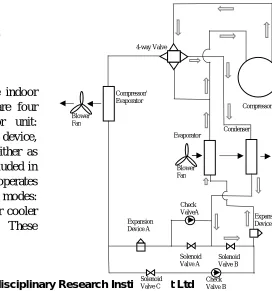
The air conditioner consists of one indoor unit and one outdoorunit. There are four major components in the indoor unit: compressor, condenser, expansion device, and evaporator [4]. The tubesact either as condenser or evaporator and are included in the outdoorunit. The air conditioner operates in one of the four operation modes: dehumidifier mode, heater mode, air cooler mode and fan blower mode. These
operationsare controlled by the switching of the valves [5].
Dehumidifier Mode: In this mode thepressurized gas refrigerantflows out of the compressor, passes through the 4-way valve, andflows through the coil of the indoor condenser coil where it gives offheat, cools down, and turns into liquid form. Then the refrigerantflows through the expansion device B, the indoor evaporator coil,and back into the compressor. The high pressure liquid refrigerantabsorbs heat as it expands into gas form and its pressure dropsalong this path. The blower fan of the indoor unit forces the air to flow into the indoor unit and pass through the evaporator unitto cool down the air so that its temperature drops below the dewpoint. Thus the water vapor in the air condenses on the surface ofthe evaporator coil, and the function of dehumidification is accomplished.Then the air flows through the condenser coil and is heatedup back to its original temperature as it leaves the air conditioner.
Fig. 1: Supervisory Control Architecture
485 modbus
Interactive Level
Operational Level Eclipse
SCADA software
PLC 1: Level 1
PLC 2: Level 2
PLC 3: Level 3
Condenser
Solenoid Valve C Expansion Device A
Check ValveA
Solenoid Valve B Solenoid
Valve A
Check Valve B
Expansion Device B Evaporator
Compressor/ Evaporator
4-way Valve
Blower Fan
Blower Fan
Compressor
Universal Multidisciplinary Research Institute Pvt Ltd
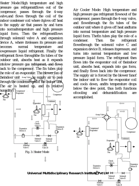
Heater Mode:High temperature and high pressure gas refrigerantflows out of the compressor, passes through the 4-way valve,and flows through the coil of the indoor condenser coil where itgives off heat to the supply air that passes by and turns into normaltemperature and high pressure liquid form. Then the refrigerantflows through solenoid valve A and expansion device A, where itreleases its pressure and becomes normal temperature and lowpressure liquid refrigerant. Finally the refrigerant flows throughthe fin tubes of the outdoor unit, absorbs heat as it expands intolow pressure gas refrigerant, and flows back to the compressor. The fin tubes play the role of an evaporator. The blower fan of theindoor unit forces the supply air to pass through the condenser coilof the indoor unit. The air is heated up, and its relative humidity islowered.
Air Cooler Mode: High temperature and high pressure gas refrigerant flowsout of the compressor, passes through the 4-way valve, and flowsthrough the fin tubes of the outdoor unit where it gives off heat andturns into normal temperature and high pressure liquid form. Thefin tubes play the role of a condenser. Then the refrigerant flowsthrough the solenoid valve C and expansion device B, releases itspressure, and turns into normal temperature and low pressure liquid form. The refrigerant then flows into the evaporator coil of theindoor unit, absorbs heat, expands into gas form, and finally flows back into the compressor. The supply air is forced by the blower fanof the indoor unit to flow the evaporator coil and cools down, andits temperature drops below the dew point, thus both functions ofcooling and dehumidification are accomplished.
Condenser
Solenoid Valve C Expansion Device A
Check Valve A
Solenoid Valve B Solenoid
Valve A
Check Valve B
Expansion Device B Evaporator
Compressor/ Evaporator
4-way Valve
Blower Fan
Blower Fan
Compressor
Fig. 3: Heater Mode
Condenser
Solenoid Valve C Expansion Device A
Check Valve A
Solenoid Valve B Solenoid
Valve A
Check Valve B
Expansion Device B Evaporator
Compressor/ Evaporator
4-way Valve
Blower Fan
Blower Fan
Compressor
Universal Multidisciplinary Research Institute Pvt Ltd
Fan Blower Mode: When the temperature
and the humidity of the
controlledenvironment is within the desired range set in the intelligent airconditioner, only the blower fan of the indoor unit operates to circulateair in the vertical farm.
4.2 Control Setup
Humidity Sensors
FX1N-EEPROM-8L
FX1N-40MR
PC
485 modbus
FX2N-4AD-PT
FX2N-4DA
FX2N-4AD
Temperature Sensors
Condenser
Solenoid Valve C Expansion
Device A Check
Valve A
Solenoid Valve B
Solenoid Valve A
Check Valve B Expansion
Device B
Evaporator
Compressor/ Evaporator 4-way Valve
Blower Fan Compressor
Universal Multidisciplinary Research Institute Pvt Ltd
5. CONCLUSION
This study integrates PLC and Eclipse SCADA software to design and build an intelligent air conditioner, and successfully applies them to the temperature and humidity control of a vertical farm of different levels. Humidity and temperature sensors are usedto measure the respective values closer to the real environment and enables the intelligent air conditioner to achieve desired settings more efficiently. The GUI can record the entire sensor data received from the sensor nodes and the air inlet of the air-conditioner, monitor the temperature and humidity at each environment node, to provide a more suitable plantation environment in vertical farming operations.
REFERENCES
[1] ImanMorsi, LoayMohy El-Din, SCADA system for oil refinery control, Measurement Vol. 47, Page 5-13, 2014
[2] Eclipse SCADA(HMI) 2012 User Manual
[3] Joao Figueiredo, Jose Sa da Costa, SCADA system for energy management in intelligent buildings, Energy and Buildings, Vol. 49, Page 85-98, 2012
[4] G.F. Hundi, A.R. Trott, T.C. Welch, Refrigeration and Air Conditioning, Elsevier, Boston, 2008
[5] Ming-Ta Yang, Cheng-Chuan Chen, Yen-Long Kuo, Implementation of intelligent air conditioner for fine agriculture, Energy and Buildings, Vol. 60, Page 364-371, 2013
![Fig. 5: Control Setup [6]](https://thumb-us.123doks.com/thumbv2/123dok_us/8829026.1787760/5.612.70.545.288.773/fig-control-setup.webp)
